

Broadband Packet Switching Technologies
.pdf360 |
WIRELESS ATM SWITCHES |
|
|
and the offered load Ž j . of each output port j are given by |
|
||
|
32 |
|
|
|
i s Ý VC Ž iy1. 32qk , |
i s 1, 2, . . . , 16, |
Ž12.5. |
|
ks1 |
|
|
and |
|
|
|
|
16 |
|
|
|
j s Ý VC jq16 k , |
j s 1, 2, . . . , 16, |
Ž12.6. |
|
ks0 |
|
|
where VC Ž iy1. 32qk and VC jq16 k are the average load of VCŽiy1. 32qk and the average load of VC jq16 k , respectively.
For simplicity, a uniform source distribution is considered, in which any burst to each input port has an equal probability of being originated from any VC, and successive choices of VC are independent. Then the average load of
each VC is the same and can be expressed as |
|
|
VC k s VC , |
k s 1, 2, . . . , 512 |
Ž12.7. |
and i in Ž12.5. and j in Ž12.6. become |
|
|
s i s j s 32 VC . |
Ž12.8. |
|
Although it was assumed that the traffic loads to each output port are uniformly distributed, the uniform distribution is no longer valid when handoff is considered. Since handoff changes the route of the corresponding VC Že.g., the output port address of the VC., the traffic load distribution to each output port is dynamically changed depending on the handoff rate. It is noted that this will affect the delay and cell loss performance of a mobilitysupport switch.
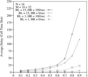
Figure 12.11 shows the average cell delay as a function of input offered load Ž i . in different situations. Here N and M are the switch size and the total number of VCs, respectively. BL means the average burst length, which is given in Ž12.3., and HR is the handoff rate, which is defined as the average number of handoffs that occur in a switch during a second. It is assumed that all VCs are mobile connections, and each VC has an equal probability of handoff. It is also assumed that each handoff is independent. As mentioned in Section 12.4, handoff requires buffering until a new connection subpath is established between a COS and the new base station that a mobile terminal is roaming to. It is assumed that this buffering time is 10 ms, allowing for the connection setup for several hops w36x. Thus, when handoff for a VC occurs, the cells of the VC are queued in the switch memory and transmitted through a different output port after 10 ms.
In Figure 12.11, the case of 100rs handoff rate is compared with the case of no handoff. The 100rs handoff rate means that the handoff of each VC
MOBILITY-SUPPORT ATM SWITCH |
361 |
Fig. 12.11 Average delay as a function of offered load.
occurs in every 5.12 s on the average, and the rate is sufficiently high to see the handoff effect of the worst case. As shown in Figure 12.11, the average cell delay of the handoff case is larger than that of the no-handoff case. This is so with both bursty ŽBL s 15. and nonbursty ŽBL s 1. traffic and is prominent with large input offered load Ž i .. For example, for an input offered load i of 0.9 and burst length BL of 15, the handoff case’s average delay Ž222.7 cell times. is almost twice as large as that in the no-handoff case Ž116.2 cell times..
There are two factors that increase the average delay in the handoff case. One is that due to handoffs of each VC, the offered loads to each output port are unbalanced, while the load distribution of each output port is assumed to be uniform for the no-handoff case. The other is that when handoff occurs, no incoming cells of the corresponding VC are served during the connection setup time of a new subpath.
Figure 12.12 shows simulation results on cell loss probability vs. buffer size. In this experiment, the switch size, the number total of VCs, and the offered load to each input port are 16, 512, and 0.9, respectively. For uniform random traffic ŽBL s 1., the required buffer size is much smaller than that for bursty traffic ŽBL s 15., and the required buffer size in the handoff case is larger than that in the no-handoff case. This shows that a COS needs a large memory for buffering cells of each handoff VC, although it uses a shared memory. For example, for bursty traffic the required buffer size in the handoff case is about 7000 cells to maintain the cell loss probability at less than 10y6 . This is at least twice as large as in the no-handoff case Žabout 3300..

362 WIRELESS ATM SWITCHES
Fig. 12.12 Cell loss probability as a function of buffer size.
Simulation results show the impact of handoffs on the performance of the mobility-support switch architecture. It can be noticed that the average cell delay in the handoff case is almost two times larger than that in the no-handoff case when the traffic load is heavy and bursty and the handoff rate is high. It can be also noticed that the required memory size in the handoff case is double that in the no-handoff case for heavily loaded bursty traffic and high handoff rate.
REFERENCES
1.D. Raychaudhuri and N. D. Wilson, ‘‘ATM-based transport architecture for multiservices wireless personal communication networks,’’ IEEE J. Select. Areas Commun., vol. 12, no. 8, pp. 1401 1414, Oct. 1994.
2.M. Umehira, M. Nakura, H. Sato, and A. Hashimoto, ‘‘ATM wireless access for mobile multimedia: concept and architecture,’’ IEEE Personal Commun., pp. 39 48, Oct. 1996.
3.D. Raychaudhuri, ‘‘Wireless ATM networks: architecture, system design and prototyping,’’ IEEE Personal Commun., pp. 42 49, Aug. 1996.
4.J. Porter and A. Hopper, ‘‘An overview of the ORL wireless ATM system,’’ Proc.
IEEE ATM Workshop, Sept. 1995.
5.E. Hyden, J. Trotter, P. Krzyzanowski, M. Srivastava, and P. Agarwal, ‘‘SWAN: an indoor wireless ATM network,’’ Proc. ICUPC ’95, Tokyo, Japan, pp. 853 857, Nov. 1995.
REFERENCES 363
6.M. J. Karol, K. Y. Eng, and M. Veeraraghavan, ‘‘BAHAMA: a broadband ad-hoc wireless ATM local area network,’’ Proc. IEEE ICC ’95, pp. 1216 1223, June 1995.
7.D. Raychaudhuri, L. Dellaverson, M. Umehira, J. Mikkonen, T. Phipps, C. Lind,
and H. Suzuki, ‘‘Charter, scope and work plan for proposed wireless ATM working group,’’ ATM Forumr96-0530rPLEN, Apr. 1996.
8.R. R. Bhat and K. Rauhala, ‘‘Draft baseline text for wireless ATM capability set 1 specification,’’ ATM ForumrBTD-WATM-01.10, Dec. 1998.
9.R. R. Bhat and R. Gupta, ‘‘Requiremets document for wireless ATM,’’ ATM Forumr98-0395rWATM, Jul. 1998.
10.G. Bautz, H. Mitts, J. Mikkonen, M. Niemi, and K. Rauhala, ‘‘A proposal for access point control protocol,’’ ATM Forumr97-0507rWATM, July 1997.
11. D. Raychaudhuri, L. J. French, R. J. Siracusa, S. K. Biswas, R. Yuan, P. Narasimhan, and C. A. Johnston, ‘‘WATMnet: a prototype wireless ATM system for multimedia personal communication,’’ IEEE J. Select. Areas Commun., vol. 15, no. 1, pp. 83 95, Jan. 1997.
12.C. A. Johnston, P. Narasimhan, J. Kokudo, and M. Ohki, ‘‘Architecture and implementation of radio access protocols in wireless ATM networks,’’ IEEE ICC ’98, Atlanta, GA, Jun. 1998.
13.R. Yuan, S. Biswas, and D. Raychaudhuri, ‘‘A signaling and control architecture
for mobility support in wireless ATM networks,’’ Proc. IEEE ICC ’96, pp. 478 484, Dallas, 1996.
14.P. Narasimhan, S. K. Biswas, C. A. Johnston, R. J. Siracusa, and H. Kim, ‘‘Design and performance of radio access protocols in WATMnet, a prototype wireless ATM network,’’ Proc. ICUPC ’97, San Diego, CA, Oct. 1997.
15.S. K. Biswas, H. Kim, P. Narasimhan, R. J. Siracusa, and C. A. Johnston, ‘‘Design and implementation of data link control protocol for CBR traffic in wireless ATM networks,’’ Proc. ICUPC ’98, Florence, Italy, Oct. 1998.
16.ORL Radio ATM project. http:rrwww.orl.co.ukrradior
17.A. Acampora and M. Naghshineh, ‘‘An architecture and methodology for mobile-executed handoff in cellular ATM networks,’’ IEEE J. Select. Areas Commun., vol. 12, no. 8, pp. 1365 1375, Oct. 1994.
18.M. J. Karol, Z. Liu, and K. Y. Eng, ‘‘Distributed-queuing request update multiple access ŽDQRUMA. for wireless packet ŽATM. networks,’’ Proc. IEEE ICC ’95, pp. 1224 1231, Jun. 1995.
19.The Magic WAND wireless ATM demonstrator. http:rrwww.tik.ee.ethz.chr wand
20.The MEDIAN project. http:rrwww.imst.dermedianrmedian.html
21.The SAMBA project. http:rrhostria.cet.ptrsambarindex.hml
22.European Telecommunications Standards Institute ŽETSI. project on Broadband Radio Access Network ŽBRAN.. http:rrwww.etsi.orgrbran
23.D. Petras et al., ‘‘Wireless ATM: performance evaluation of a DSAqqMAC protocol with fast collision resolution by a probing algorithm,’’ Int. J. Wireless Inf. Networks, vol. 4, no. 4, 1997.
24.F. Bauchot et al., ‘‘MASCARA: a MAC protocol for wireless ATM,’’ ACTS Mobile Summit, Granada, Spain, Nov. 1996.
364 WIRELESS ATM SWITCHES
25.P. Narasimhan et al., ‘‘Proposal for radio transport convergence, medium access control, and logical link control layers for wireless ATM,’’ ETSI BRAN 4, London, Sep. 1997.
26.H. Hashemi, ‘‘The indoor radio propagation channel,’’ Proc. IEEE, vol. 81, no. 7, pp. 943 968, Jul. 1993.
27.C. -K. Toh, ‘‘Crossover switch discovery for wireless ATM LANs,’’ ACM J. Mobile Networks Appl., vol. 1, no. 2, pp. 145 165, Oct. 1996.
28.B. Rajagopalan, ‘‘Mobility management in integrated wireless-ATM networks,’’
Proc. 1st Int. Conf. on Mobile Computing and Networking, Berkeley, CA, Nov. 1995.
29.A. Acharya, J. Li, B. Rajagopalan, and D. Raychaudhuri, ‘‘Mobility management in wireless ATM networks,’’ IEEE Commun. Mag., vol. 35, no. 11, pp. 100 109, Nov. 1997.
30.J. H. Condon et al., ‘‘Rednet: a wireless ATM local area network using infrared links,’’ Proc. of 1st Int. Conf. on Mobile Computing and Networking, pp. 151 159, Berkeley, CA, Nov. 1995.
31.B. A. Akyol and D. C. Cox, ‘‘Rerouting for handoff in a wireless ATM network,’’ IEEE Personal Commun., pp. 26 33, Oct. 1996.
32.C.-K. Toh and B. Akyol, ‘‘A survey of handover techniques in wireless ATM networks,’’ Int. Wireless Inf. Networks J., vol. 5, no. 1, 1998.
33.H. Kim and H. J. Chao, ‘‘Design of a mobility-support ATM switch,’’ Proc. Globecom’98, Sydney, Australia, Nov. 1998.
34.H. J. Chao and N. Uzun, ‘‘A VLSI sequencer chip for ATM traffic shaper and queue manager,’’ IEEE J. Solid-State Circuits, vol. 9, no. 7, pp. 1634 1643, Nov. 1992.
35.H. J. Chao, H. Cheng, Y. R. Jeng, and D. Jeong, ‘‘Design of a generalized priority queue manager for ATM switches,’’ IEEE J. Select. Areas Commun., vol. 15, no. 5, pp. 867 880, Jun. 1997.
36.S. K. Biswas, ‘‘Handling realtime traffic in mobile networks,’’ Ph.D. Thesis, University of Cambridge Computer Laboratory, Sep. 1994.

Broadband Packet Switching Technologies: A Practical Guide to ATM Switches and IP Routers
H. Jonathan Chao, Cheuk H. Lam, Eiji Oki
Copyright 2001 John Wiley & Sons, Inc. ISBNs: 0-471-00454-5 ŽHardback.; 0-471-22440-5 ŽElectronic.
CHAPTER 13
IP ROUTE LOOKUPS
The emergence of new multimedia networking applications and the growth of the Internet due to the exponentially increasing number of users, hosts, and domains have led to a situation where network capacity is becoming a scarce resource. In order to maintain the good service, three key factors have been considered in designing IP networks: large-bandwidth links, high router data throughput, and high packet forwarding rates w16x. With the advent of fiber optics, which provides fast links, and the current switching technology, which is applied for moving packets from the input interface of a router to the corresponding output interface at gigabit speeds, the first two factors can be readily handled. Therefore, the key to the success of the next generation IP networks is the deployment of high-performance routers to forward the packets at the high speeds.
There are many tasks to be performed in packet forwarding; packet header encapsulation and decapsulation, updating a time-to-live ŽTTL. field in each packet header, classifying the packets into queues for specific service classes, etc. The major task, which seems to dominate the processing time of the incoming packet, is searching for the next-hop information of the appropriate prefix matching the destination address from a routing table. This is also called an IP route lookup.
As the Internet has evolved and grown over in recent years, it has been proved that the IP address space, which is divided into classes A, B, and C, is inflexible and wasteful. Class C, with a maximum of 254 host addresses, is too small, while class B, which allows up to 65,534 addresses, is too large for most organizations. The lack of a network class of a size that is appropriate for mid-sized organization results in exhaustion of the class B network address
365
366 IP ROUTE LOOKUPS
space. In order to use the address space efficiently, bundles of class C addresses were given out instead of class B addresses. This also causes massive growth of routing table entries.
To reduce the number of routing table entries, classless interdomain routing ŽCIDR. w4x was introduced to allow for arbitrary aggregation of networks. A network that has identical routing information for all subnets except a single one requires only two entries in the routing table: one for the specific subnet Žwhich has preference if it is matched. and the other for the remaining subnets. This decreases the size of the routing table and results in better usage of the available address space. On the other hand, an efficient mechanism to do IP route lookups is required.
In the CIDR approach, a routing table consists of a set of IP routes. Each IP route is represented by a ²route prefixrprefix length: pair. The prefix length indicates the number of significant bits in the route prefix. Searching is done in a longest-matching manner. For example, a routing table may have the prefix routes ²12.0.54.8r32:, ²12.0.54.0r24:, and ²12.0.0.0r16:. If a packet has the destination address ²12.0.54.2:, the second prefix route is matched, and its next hop is retrieved and used for forwarding the packet.
This chapter is organized as follows: Starting from Section 13.1, the architectures of generic routers are described and the design criteria that should be considered for IP lookups is discussed. Recently, there have
been a number of techniques proposed |
to provide fast IP lookups |
w2, 3, 5, 6, 9, 12, 14, 15, 16x. From Section 13.2 |
to Section 13.9 we will look at |
several IP route-lookup schemes proposed over the past few years.
13.1IP ROUTER DESIGN
13.1.1Architectures of Generic Routers
The architectures of generic routers can be broadly classified into two categories. One is schematically shown in Figure 13.1. A number of network interfaces, forwarding engines, and a network processor are interconnected with a switching fabric. Inbound interfaces send packet headers to the forwarding engines through the switching fabric. The forwarding engines in turn determine which outgoing interface the packet should be sent to. This information is sent back to the inbound interface, which forwards the packet to the outbound interface. The only task of a forwarding engine is to process packet headers. All other tasks such as participating in routing protocols, resource reservation, handling packets that need extra attention, and other administrative duties are handled by the network processor. The BBN multigigabit router w13x is an example of this design.
Another router architecture is shown in Figure 13.2. Here, processing elements in the inbound interface decide to which outbound interface

IP ROUTER DESIGN |
367 |
Fig. 13.1 Router design with forwarding engines.
Fig. 13.2 Router design with processing power on interfaces.
packets should be sent. The GRF routers from Ascend Communications, for instance, use this design.
The forwarding engines in Figure 13.1 and the processing elements in Figure 13.2 use a local version of the routing table a forwarding table, downloaded from the network processor to make their routing decisions. It is not necessary to download a new forwarding table for each routing update. Routing updates can be frequent, but since routing protocols need time on the order of minutes to converge, forwarding tables can be allowed to grow a little stale and need not change more than once per second.
The network processor needs a dynamic routing table designed for fast updates and fast generation of forwarding tables. The forwarding tables, on the other hand, can be optimized for lookup speed and need not be dynamic.
368 IP ROUTE LOOKUPS
13.1.2IP Route Lookup Design
When designing the data structure used in the forwarding table, the primary goal is to minimize lookup time. To reach that goal, two parameters should be simultaneously minimized:
the number of memory accesses required during lookups, and
the size of the data structure.
Reducing the number of memory accesses required during a lookup is important because memory accesses are relatively slow and usually the bottleneck of lookup procedures. If the data structure can be made small enough, it can fit entirely in the cache of a conventional microprocessor. This means that memory accesses will be orders of magnitude faster than if the data structure needs to reside in memory consisting of the relatively slow DRAM.
If the forwarding table does not fit entirely in the cache, it is still beneficial if a large fraction of the table can reside in cache. Locality in traffic patterns will keep the most frequently used pieces of the data structure in cache, so that most lookups will be fast. Moreover, it becomes feasible to use fast SRAM for the small amount of needed external memory. SRAM is expensive, and the faster it is, the more expensive it is. For a given cost, the SRAM can be faster if less is needed.
As secondary design goals, the data structure should
need few instructions during lookup, and
keep the entities naturally aligned as much as possible to avoid expensive instructions and cumbersome bit-extraction operations.
These goals have a second-order effect on the performance of the data structure.
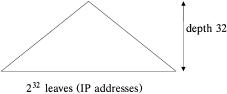
For the purpose of understanding the data structure, imagine a binary tree that spans the entire IP address space ŽFig. 13.3.. Its height is 32, and the number of its leaves is 232 , one for each possible IP address. The prefix of a routing table entry defines a path in the tree ending in some node. All IP
Fig. 13.3 Binary tree spanning the entrie IP address space.

IP ROUTE LOOKUP BASED ON STANDARD TRIE STRUCTURE |
369 |
Fig. 13.4 Routing entries defining ranges of IP addresses.
addresses Žleaves. in the subtree rooted at that node should be routed according to that routing entry. In this manner each routing table entry defines a range of IP addresses with identical routing information Žnext-hop IP address..
If several routing entries cover the same IP address, the rule of the longest match is applied; it states that for a given IP address, the routing entry with the longest matching prefix should be used. This situation is illustrated in Figure 13.4; the routing entry e1 is hidden by e2 for addresses in the range r.
13.2IP ROUTE LOOKUP BASED ON CACHING TECHNIQUE
One possible IP route-lookup approach uses a caching technique where the routing entries of the most recently used destination addresses are kept in a cache. The technique relies on there being enough locality in the traffic so that the cache hit rate is sufficiently high and the cost of a routing lookup is amortized over several packets. These caching methods have worked well in the past. However, as the current rapid growth of the Internet increases, the required size of address caches and hardware caches might become uneconomical.
13.3 IP ROUTE LOOKUP BASED ON STANDARD TRIE STRUCTURE
A trie structure is a multiway tree in which each node contains zero or more pointers to its child nodes. In the 1-bit trie structure w8x, each node contains two pointers, the 0-pointer and the 1-pointer. A node X at level h represents the set of all route prefixes that have the same h bits as their first bits. Depending on the value of the Žh q 1.th bit, 0 or 1, each pointer of the node X points to the corresponding subtree Žif it exists., which represents the set of all route prefixes that have the same Žh q 1.th bits as their first bits. Each IP lookup starts at the root node of the trie. Based on the value of each bit of the destination address of the packet, the lookup algorithm determines the next node to be visited. The next hop of the longer matching prefix found along the path is maintained while the trie is traversed.