

CISSP - Certified Information Systems Security Professional Study Guide, 2nd Edition (2004)
.pdfCommunications and Network Security |
71 |
Carrier-Sense Multiple Access with Collision Detection (CSMA/CD) The LAN media access technology that performs communications using the following steps:
1.The host listens to the LAN media to determine if it is in use.
2.If the LAN media is not currently being used, the host transmits its communication.
3.While transmitting, the host listens for collisions (i.e., two or more hosts transmitting simultaneously).
4.If a collision is detected, the host transmits a jam signal.
5.If a jam signal is received, all hosts stop transmitting. Each host waits a random period of time and then starts over at step 1.
Ethernet is a specific example of a CSMA/CD protocol.
Token Passing The LAN media access technology that performs communications using a digital token. Possession of the token allows a host to transmit data. Once its transmission is complete, it releases the token on to the next system. Token passing is used by Token Ring networks, such as FDDI.
Polling The LAN media access technology that performs communications using a masterslave configuration. One system is labeled as the primary system. All other systems are labeled as secondary. The primary system polls or inquires of each secondary system in turn whether they have a need to transmit data. If a secondary system indicates a need, it is granted permission to transmit. Once its transmission is complete, the primary system moves on to poll the next secondary system. Synchronous Data Link Control (SDLC) uses polling.
Network Topologies
The physical layout and organization of computers and networking devices is known as the network topology. The logical topology is the grouping of networked systems into trusted collectives. The physical topology is not always the same as the logical topology. There are four basic topologies of the physical layout of a network: ring, bus, star, and mesh.
Ring Topology
A ring topology connects each system as points on a circle (see Figure 3.6). The connection medium acts as a unidirectional transmission loop. Only one system can transmit data at a time. Traffic management is performed by a token. A token is a digital hall pass that travels around the ring until a system grabs it. A system in possession of the token can transmit data. Data and the token are transmitted to a specific destination. As the data travels around the loop, each system checks to see if it is the intended recipient of the data. If not, it passes the token on. If so, it reads the data. Once the data is received, the token is released and returns to traveling around the loop until another system grabs it. If any one segment of the loop is broken, all communication around the loop ceases. Some implementations of ring topologies employ a fault tolerance mechanism, such as dual loops running in opposite directions, to prevent single points of failure.

72 Chapter 3 ISO Model, Network Security, and Protocols
F I G U R E 3 . 6 A ring topology
Bus Topology
A bus topology connects each system to a trunk or backbone cable. All systems on the bus can transmit data simultaneously, which can result in collisions. A collision occurs when two systems transmit data at the same time; the signals interfere with each other. To avoid this, the systems employ a collision avoidance mechanism that basically “listens” for any other currently occurring traffic. If traffic is heard, the system waits a few moments and listens again. If no traffic is heard, the system transmits its data. When data is transmitted on a bus topology, all systems on the network hear the data. If the data is not addressed to a specific system, that system just ignores the data. The benefit of a bus topology is that if a single segment fails, communications on all other segments continue uninterrupted. However, the central trunk line remains a single point of failure.
There are two types of bus topologies: linear and tree. A linear bus topology employs a single trunk line with all systems directly connected to it. A tree topology employs a single trunk line with branches that can support multiple systems. Figure 3.7 illustrates both types.
F I G U R E 3 . 7 A linear topology and a tree bus topology
Linear |
Tree |

Communications and Network Security |
73 |
Star Topology
A star topology employs a centralized connection device. This device can be a simple hub or switch. Each system is connected to the central hub by a dedicated segment (see Figure 3.8). If any one segment fails, the other segments can continue to function. However, the central hub is a single point of failure. Generally, the star topology uses less cabling than other topologies and makes the identification of damaged cables easier.
A logical bus and a logical ring can be implemented as a physical star. Ethernet is a bus-based technology. It can be deployed as a physical star, but the hub device is actually a logical bus connection device. Likewise, Token Ring is a ring-based technology. It can be deployed as a physical star using a multistation access unit (MAU). An MAU allows for the cable segments to be deployed as a star while internally the device makes logical ring connections.
Mesh Topology
A mesh topology connects systems to other systems using numerous paths (see Figure 3.9). A full mesh topology connects each system to all other systems on the network. A partial mesh topology connects many systems to many other systems. Mesh topologies provide redundant connections to systems, allowing multiple segment failures without seriously affecting connectivity.
TCP/IP Overview
The most widely used protocol is TCP/IP, but it is not just a single protocol; rather, it is a protocol stack comprising dozens of individual protocols (see Figure 3.10). TCP/IP is a platformindependent protocol based on open standards. However, this is both a benefit and a drawback. TCP/IP can be found in just about every available operating system, but it consumes a significant amount of resources and is relatively easy to hack into because it was designed for ease of use rather than for security.
F I G U R E 3 . 8 A star topology

74 Chapter 3 ISO Model, Network Security, and Protocols
F I G U R E 3 . 9 A mesh topology
F I G U R E 3 . 1 0 |
The four layers of TCP/IP and its component protocols |
|
|
|||||||||||
|
|
|
|
|
|
|
|
|
|
|
|
|
|
|
|
Application |
|
|
|
FTP |
|
Telnet |
|
SNMP |
|
LPD |
|||
|
|
|
|
Process/ |
|
|
|
|
||||||
|
Presentation |
|
|
|
|
|
|
|
|
|
|
|
||
|
|
Application |
|
TFTP |
|
SMTP |
|
NFS |
|
X Window |
||||
|
|
|
|
|
|
|
|
|||||||
|
Session |
|
|
|
|
|
|
|
||||||
|
|
|
|
|
|
|
|
|
|
|
|
|
|
|
|
|
|
|
|
|
|
|
|
|
|
|
|
|
|
|
|
|
|
|
|
|
|
|
|
|
|
|
|
|
|
Transport |
|
|
Host-to-Host |
|
|
TCP |
|
|
UDP |
||||
|
|
|
|
|
|
|
|
|
|
|
|
|
|
|
|
|
|
|
|
|
|
|
|
|
|
|
|
|
|
|
Network |
|
|
Internet |
|
ICMP |
|
|
ARP |
|
|
RARP |
||
|
|
|
|
|
|
|
|
|
|
|
|
|
||
|
|
|
|
|
|
|
IP |
|
|
|
|
|||
|
|
|
|
|
|
|
|
|
|
|
|
|
||
|
|
|
|
|
|
|
|
|
|
|
|
|
|
|
|
Data Link |
|
|
Network |
|
Ethernet |
|
Fast Ethernet |
|
Token Ring |
FDDI |
|||
|
|
|
|
|
|
|
||||||||
|
Physical |
|
|
Access |
|
|
|
|||||||
|
|
|
|
|
|
|
|
|
|
|
|
|
||
|
|
|
|
|
|
|
|
|
|
|
|
|
|
|
|
|
|
|
|
|
|
|
|
|
|
|
|
|
|
TCP/IP can be secured using VPN links between systems. VPN links are encrypted to add privacy, confidentiality, and authentication and to maintain data integrity. Protocols used to establish VPNs are Point-to-Point Tunneling Protocol (PPTP), Layer 2 Tunneling Protocol (L2TP), and Internet Protocol Security (IPSec). Another method is to employ TCP wrappers. A TCP wrapper is an application that can serve as a basic firewall by restricting access based on user IDs or system IDs. Using TCP wrappers is a form of port-based access control.

Communications and Network Security |
75 |
Transport Layer Protocols
The two primary Transport layer protocols of TCP/IP are TCP and UDP. TCP is a connectionoriented protocol, whereas UDP is a connectionless protocol. When a communication connection is established between two systems, it is done using ports. TCP and UDP each have 65,536 ports. A port is little more than an address number that both ends of the communication link agree to use when transferring data. The first 1,024 of these ports (0–1,023) are called the wellknown ports or the service ports. This is because they have standardized assignments as to the services they support. For example, port 80 is the standard port for Web (HTTP) traffic, port 23 is the standard port for Telnet, and port 25 is the standard port for SMTP.
Transmission Control Protocol (TCP) operates at layer 4 (the Transport layer) of the OSI model. It supports full-duplex communications, is connection oriented, and employs reliable virtual circuits. TCP is connection-oriented because it employs a handshake process between two systems to establish a communication session. Upon completion of this handshake process, a communication session that can support data transmission between the client and server is established. The three-way handshake process is as follows:
1.The client sends a SYN (synchronize) packet to the server.
2.The server responds with a SYN/ACK (synchronize and acknowledge) packet back to the client.
3.The client responds with an ACK (acknowledge) packet back to the server.
The segments of a TCP transmission are sequenced. This allows the receiver to rebuild the original communication by reordering received segments back into their proper arrangement in spite of the order in which they were received. Data communicated through a TCP session is periodically verified with an acknowledgement signal. The acknowledgement is a hash value of all previously transmitted data. If the server’s own hash of received data does not match the hash value sent by the client, the server asks the client to resend the last collection of data. The number of packets transmitted before an acknowledge packet is sent is known as the transmission window. Data flow is controlled through a mechanism called sliding windows. TCP is able to use different sizes of windows (i.e., a different number of transmitted packets) before sending an acknowledgement. Larger windows allow for faster data transmission, but they should be used only on reliable connections where lost or corrupted data is minimal. Smaller windows should be used when the communication connection is unreliable. TCP should be employed when delivery of data is required.
User Datagram Protocol (UDP) also operates at layer 4 (the Transport layer) of the OSI model. It is a connectionless “best effort” communications protocol. It offers no error detection or correction, does not use sequencing, does not use flow control mechanisms, does not use a virtual circuit, and is considered unreliable. UDP has very low overhead and thus can transmit data quickly. However, UDP should be used only when delivery of data is not essential. UDP is often employed by real-time or streaming communications for audio or video.
Network Layer Protocols
Another important protocol in the TCP/IP protocol suite operates at the Network layer of the OSI model—namely Internet Protocol (IP). IP provides route addressing for data packets. Similar to

76 Chapter 3 ISO Model, Network Security, and Protocols
UDP, IP is connectionless and is an unreliable datagram service. IP does not offer guarantees that packets will be delivered or that packets will be delivered in the correct order, nor does it guarantee that packets will not be delivered more than once. Thus, you must employ TCP on IP to gain reliable and controlled communication sessions.
Other protocols at the OSI model Network layer include ICMP, IGMP, and NAT.
ICMP
Internet Control Message Protocol (ICMP) is used to determine the health of a network or a specific link. The PING utility employs ICMP echo packets and bounces them off remote systems. Thus, PING can be used to determine if the remote system is online, if the remote system is responding promptly, whether the intermediary systems are supporting communications, and the level of performance efficiency at which the intermediary systems are communicating. PING includes a redirect function that allows the echo responses to be sent to a different destination than the system of origin. Unfortunately, this ICMP capability is often exploited in various forms of bandwidth-based denial of service attacks.
IGMP
Internet Group Management Protocol (IGMP) allows systems to support multicasting. Multicasting is the transmission of data to multiple specific recipients. RFC 1112 discusses the requirements to perform IGMP multicasting.
NAT
Network Address Translation (NAT) was developed to allow private networks to use any IP address set without causing collisions or conflicts with public Internet hosts with the same IP addresses. In effect, NAT translates the IP addresses of your internal clients to leased addresses outside of your environment. Most often, a private network employs the private IP addresses defined in RFC 1918. The private IP address ranges are 10.0.0.0–10.255.255.255, 172.16.0.0–172.31.255.255, and 192.168.0.0–192.168.255.255. These ranges of IP addresses are defined by default on routers as nonroutable. They are reserved for use by private networks. Attempting to use these addresses directly on the Internet is futile because all publicly accessible routers will drop data packets containing a source or destination IP address from these ranges.
NAT can be used in two modes: static and dynamic. Static mode NAT is used when a specific internal client's IP address is assigned a permanent mapping to a specific external public IP address. This allows for external entities to communicate with systems inside of your network even if you are using the RFC 1918 IP addresses. Dynamic mode NAT is used to grant multiple internal clients access to a few leased public IP addresses. Thus, a large internal network can still access the Internet without having to lease a large block of public IP addresses. This keeps public IP address usage abuse to a minimum and helps keep Internet access costs to a minimum. In a dynamic mode NAT implementation, the NAT system maintains a database of mappings so all response traffic from Internet services are properly routed back to the original internal requesting client. Often NAT is combined with a proxy server or proxy firewall to provide additional Internet access and content caching features. NAT is not directly compatible with IPSec because it modifies packet headers, which IPSec relies upon to prevent security violations.

Communications and Network Security |
77 |
Data Link Layer Protocols
Among the protocols at the Data Link layer (layer 2) of the OSI model, the two you should be familiar with are Address Resolution Protocol (ARP) and Reverse Address Resolution Protocol (RARP). ARP is used to resolve IP addresses into MAC addresses. MAC addresses are the sixdigit hexadecimal numbers assigned by manufacturers to network interface cards. Traffic on a network segment (e.g., cables across a hub) is directed from its source system to its destination system using MAC addresses. RARP is used to resolve MAC addresses into IP addresses.
In the Application layer of the TCP/IP model (which includes the Session, Presentation, and Application layers of the OSI model) reside numerous applicationor service-specific protocols. A basic knowledge of these protocols and their relevant service ports is important for the CISSP exam:
Telnet, port 23 A terminal emulation network application that supports remote connectivity for executing commands and running applications but that does not support transfer of files.
File Transfer Protocol (FTP), ports 20, 21 A network application that supports an exchange of files that requires anonymous or specific authentication.
Trivial File Transfer Protocol (TFTP), port 69 |
A network application that supports an |
exchange of files that does not require authentication. |
|
Simple Mail Transfer Protocol (SMTP), port 25 |
A protocol used to transmit e-mail messages |
from a client to an e-mail server and from one e-mail server to another.
Post Office Protocol (POP3), port 110 A protocol used to pull e-mail messages from an inbox on an e-mail server down to an e-mail client.
Line Print Daemon (LPD) A network service that is used to spool print jobs and to send print jobs to printers.
X Window A GUI API for operating systems.
Bootstrap Protocol (BootP) A protocol used to connect diskless workstations to a network through auto-assignment of IP configuration and download of basic OS elements. BootP is the forerunner to Dynamic Host Configuration Protocol (DHCP).
Network File System (NFS) A network service used to support file sharing between dissimilar systems.
Simple Network Management Protocol (SNMP), port 161 A network service used to collect network health and status information by polling monitoring devices from a central monitoring station.
TCP/IP’s vulnerabilities are numerous. Improperly implemented TCP/IP stacks in various operating systems are vulnerable to buffer overflows, SYN flood attacks, various DoS attacks, fragment attacks, over-sized packet attacks, spoofing attacks, man-in-the-middle attacks, hijack attacks, and coding error attacks.
In addition to these intrusive attacks, TCP/IP (as well as most protocols) is also subject to passive attacks via monitoring or sniffing. Network monitoring is the act of monitoring traffic patterns to obtain information about a network. Packet sniffing is the act of capturing packets from the network in hopes of extracting useful information from the packet contents. Effective packet sniffers can extract usernames, passwords, e-mail addresses, encryption keys, credit card numbers, IP addresses, system names, and so on.

78 Chapter 3 ISO Model, Network Security, and Protocols
Internet/Intranet/Extranet Components
The Internet is the global network of interconnected networks that provides the wealth of information we know as the World Wide Web. The Internet is host to countless information services and numerous applications, including the Web, e-mail, FTP, Telnet, newsgroups, chat, and so on. The Internet is also home to malicious persons whose primary goal is to locate your computer and extract valuable data from it, use it to launch further attacks, or damage it in some way. You should be familiar with the Internet and able to readily identify its benefits and drawbacks from your own online experiences. Due to the success and global use of the Internet, many of its technologies were adapted or integrated into the private business network. This created two new forms of networks: intranets and extranets.
An intranet is a private network that is designed to host the same information services found on the Internet. Networks that rely upon external servers (i.e., ones positioned on the public Internet) to provide information services internally are not considered intranets. Intranets provide users with access to the Web, e-mail, and other services on internal servers that are not accessible to anyone outside of the private network.
An extranet is a cross between the Internet and an intranet. An extranet is a section of an organization’s network that has been sectioned off so that it acts as an intranet for the private network but also serves information out to the public Internet. An extranet is often reserved for use by specific partners or customers. It is rarely on a public network. An extranet for public consumption is typically labeled a demilitarized zone (DMZ), or perimeter network.
When you’re designing a secure network (whether a private network, an intranet, or an extranet), there are numerous networking devices that must be evaluated. Not all of these components are necessary for a secure network, but they are all common network devices that may have an impact on network security.
Firewalls
Firewalls are essential tools in managing and controlling network traffic. A firewall is a network device used to filter traffic and is typically deployed between a private network and a link to the Internet, but it can be deployed between departments within an organization. Without firewalls, it would not be possible to restrict malicious traffic from the Internet from entering into your private network. Firewalls filter traffic based on a defined set of rules, also called filters or access control lists. They are basically a set of instructions that are used to distinguish authorized traffic from unauthorized and/or malicious traffic. Only authorized traffic is allowed to cross the security barrier provided by the firewall.
Firewalls are useful for blocking or filtering traffic. They are most effective against unrequested traffic and attempts to connect from outside the private network and for blocking known malicious data, messages, or packets based on content, application, protocol, port, or source address. They are capable of hiding the structure and addressing scheme of a private network from the public. Most firewalls offer extensive logging, auditing, and monitoring capabilities, as well as alarms and basic intrusion detection system (IDS) functions. Firewalls are unable to block viruses or malicious code transmitted through otherwise authorized communication channels, prevent unauthorized but accidental or intended disclosure of information by users, prevent attacks by malicious users already behind the firewall, or protect data after it passes out of or into the private network.

Internet/Intranet/Extranet Components |
79 |
Firewalls are only one part of an overall security solution. With a firewall, many of the security mechanisms are concentrated in one place, and thus they may be a single point of failure. Firewall failure is most commonly caused by human error and misconfiguration. Firewalls provide protection only against traffic that crosses the firewall from one subnet to another. They offer no protection against traffic within a subnet (i.e., behind a firewall).
There are four basic types of firewalls: static packet-filtering firewalls, application-level gateway firewalls, circuit-level gateway firewalls, and stateful inspection firewalls. There are also ways to create hybrid or complex gateway firewalls by combining two or more of these firewall types into a single firewall solution. In most cases, having a multilevel firewall provides greater control over filtering traffic. Regardless, let’s look at the various firewall types and discuss firewall deployment architectures as well.
Static Packet-Filtering Firewall
A static packet-filtering firewall filters traffic by examining data from a message header. Usually, the rules are concerned with source, destination, and port addresses. Using static filtering, a firewall is unable to provide user authentication or to tell whether a packet originated from inside or outside the private network, and it is easily fooled with spoofed packets. Static packetfiltering firewalls are known as first-generation firewalls; they operate at layer 3 (the Network layer) of the OSI model. They can also be called screening routers or common routers.
Application-Level Gateway Firewall
An application-level gateway firewall is also called a proxy firewall. A proxy is a mechanism that copies packets from one network into another; the copy process also changes the source and destination address to protect the identity of the internal or private network. An application-level gateway firewall filters traffic based on the Internet service (i.e., application) used to transmit or receive the data. Each type of application must have its own unique proxy server. Thus, an application-level gateway firewall comprises numerous individual proxy servers. This type of firewall negatively affects network performance because each packet must be examined and processed as it passes through the firewall. Application-level gateways are known as second-generation firewalls, and they operate at the Application layer (layer 7) of the OSI model.
Circuit-Level Gateway Firewalls
Circuit-level gateway firewalls are used to establish communication sessions between trusted partners. They operate at the Session layer (layer 5) of the OSI model. SOCKS (SOCKetS, as in TCP/IP ports) is a common implementation of a circuit-level gateway firewall.
Stateful Inspection Firewalls
Stateful inspection firewalls evaluate the state or the context of network traffic. By examining source and destination addresses, application usage, source of origin, and the relationship between current packets and the previous packets of the same session, stateful inspection firewalls are able to grant a broader range of access for authorized users and activities and actively watch for and block unauthorized users and activities. Stateful inspection firewalls generally operate more efficiently than application-level gateway firewalls. They are known as third-generation firewalls, and they operate at Network and Transport layers (layers 3 and 4) of the OSI model.
80 Chapter 3 ISO Model, Network Security, and Protocols
Multihomed Firewalls
Some firewall systems have more than one interface. For instance, a multihomed firewall must have at least two interfaces to filter traffic (they’re also known as dual-homed firewalls). All multihomed firewalls should have IP forwarding disabled to force the filtering rules to control all traffic rather than allowing a software-supported shortcut between one interface and another. A bastion host or a screened host is just a firewall system logically positioned between a private network and an untrusted network. Usually, the bastion host is located behind the router that connects the private network to the untrusted network. All inbound traffic is routed to the bastion host, which in turn acts as a proxy for all of the trusted systems within the private network. It is responsible for filtering traffic coming into the private network as well as for protecting the identity of the internal client. A screened subnet is similar to the screened host in concept, except a subnet is placed between two routers and the bastion host is located within that subnet. All inbound traffic is directed to the bastion host, and only traffic proxied by the bastion host can pass through the second router into the private network.
Firewall Deployment Architectures
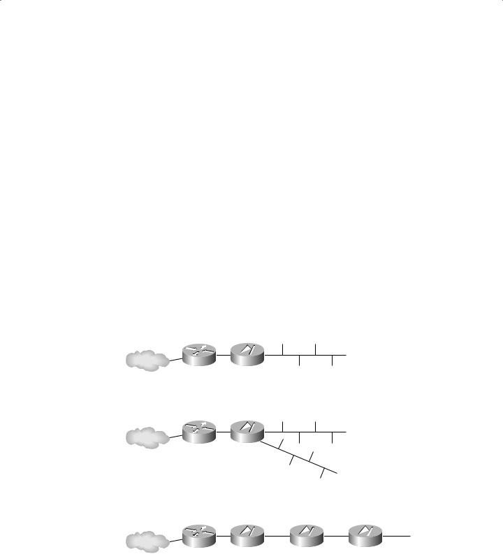
There are three commonly recognized firewall deployment architectures: single-tier, two-tier, and three-tier (also known as multitier). As you can see in Figure 3.11, a single-tier deployment places the private network behind a firewall, which is then connected through a router to the Internet (or some other untrusted network). Single-tier deployments are useful against generic attacks only. This architecture offers only minimal protection.
F I G U R E 3 . 1 1 Three firewall deployment architectures
Private Network
Router Firewall
Internet
Single-Tier
Private Network
Router Firewall
Internet
DMZ
Two-Tier
Router |
Firewall |
Firewall |
|
|
Firewall |
|
|
|
||
Internet |
|
|
|
|
|
|
|
|
|
|
|
|
|
|
|
|
|
|
|
|
|
|
|
|
|
|
|
|
|
|
|
|
|
DMZ |
|
Transaction |
Backoffice |
||||||
|
Three-Tier |
|
Subnet |
Subnet |
||||||
|
|
|
|
|
|
|
|
|||