CIR errata Oct98
.pdfIrDA Control Errata, 1998
IrDA Control Errata to
IrDA Control Specification version 1.0
Last Modified: Oct 26, 1998
Following are a list of corrections/clarifications and suggested amendments or changes to the IrDA Control specification Version 1.0 dated June 30, 1998. The closed errata are organized by the date they were closed. Open errata are at the end.
The closed errata should be considered an integral part of the IrDA Control version 1.0 specification. No change to the version number is required based on these changes.
The points are classified according to the following scheme:
∙CORRECTION: a change required to correct an error in the existing document corrections may change the specified behavior of the protocol to match that which was originally intended by the authors
∙CLARIFICATION: textual enhancement that provides clearer explanation of a protocol element without changing any behavior
∙MODIFICATION: a modification of the currently specified behavior that adds but does not delete any function from the protocol
∙CHANGE: a modification of the currently specified protocol that may add and or delete function from the protocol
∙PROBLEM: a known problem for which an alteration to the document has yet to be proposed.
1. JULY 1998 – CLOSED ERRATA .......................................................................................................... |
3 |
|
1.1 |
CRC FIELD (3.2.3) ................................................................................................................................ |
3 |
2. OCTOBER 1998 – CLOSED ERRATA................................................................................................. |
6 |
|
2.1 CORRECTIONS FOR FIGURES AND TABLES .............................................................................................. |
6 |
|
2.2 |
DC-BIASED SCHEME ........................................................................................................................... |
13 |
3. OPEN ERRATA.................................................................................................................................... |
18 |
|
3.1 APPENDIX D........................................................................................................................................ |
18 |
|
3.2 |
FIGURE E.2......................................................................................................................................... |
22 |
3.3 |
FIGURE 4.4 (4.3.2) .............................................................................................................................. |
22 |
3.4 |
UNBINDING (4.3.3).............................................................................................................................. |
23 |
3.5 |
SLEEP MODE (4.4.1)............................................................................................................................ |
23 |
3.6 |
HOST REQUIREMENTS (4.5.1) / PERIPHERAL REQUIREMENTS (4.5.2).................................................... |
23 |
3.7 |
TABLE5.3 (5.3).................................................................................................................................... |
23 |
3.8 |
EXAMPLE DESCRIPTORS (F.9).............................................................................................................. |
24 |
1
|
|
IrDA Control Errata, 1998 |
3.9 REMARKS FOR MULTIPLE HOSTS .......................................................................................................... |
24 |
|
3.10 |
MAC CONTROL FIELD (4.2.3) ............................................................................................................ |
25 |
3.11 |
ENUMERATION (4.3.1) ....................................................................................................................... |
25 |
3.12 |
FIGURE 4.5 (4.5) ............................................................................................................................... |
25 |
3.13 HOST MAC PROTOCOL MACHINE (4.7.3) ........................................................................................... |
26 |
|
3.14 |
PROTOCOL PERIPHERAL MACHINE (4.7.4).......................................................................................... |
26 |
3.15 GET_DESCRIPTOR (5.3.1)............................................................................................................. |
27 |
|
3.16 |
SET_MODE (5.3.1) / FIGURE 5.4 (5.3.3) / (APPENDIX F.8) ............................................................... |
28 |
3.17 |
GET_STATUS (5.3.1) / FIGURE 5.3 (5.3.3) / (APPENDIX F.8)............................................................ |
29 |
3.18 |
IRDA CONTROL DESCRIPTOR / TABLE5.6 (5.3.5) ............................................................................... |
29 |
3.19 |
CONFIGURATION DESCRIPTOR (F.9)................................................................................................... |
30 |
3.20 |
DITHERING HOST ALGORITHM (G.5) .................................................................................................. |
30 |
2
IrDA Control Errata, 1998
1. July 1998 –Closed Errata
All errata in this section were approved and closed at the July 1998 IrDA meeting.
1.1 CRC Field (3.2.3)
CLARIFICATION
An example of VHDL implementation follows to describes the process.
For better understanding of CRC calculation algorithm, an example of VHDL implementation is described.
library IEEE;
use IEEE.std_logic_1164.all; use WORK.all;
entity TxCRC is |
|
|
port( |
|
|
TxRESET :in |
|
std_logic; |
TxLongFrame :in std_logic; |
|
|
TX_CRCCLK :in |
|
std_logic; |
TXCRCIN :in |
|
std_logic; |
ADDTXCRC :in std_logic; |
|
|
CRCOUT :out |
|
std_logic |
------------------------------------------------------------ |
||
-- TxRESET |
... Reset signal for this module |
|
-- TxLongFrame |
... H for long frame, L for short frame |
|
-- TX_CRCCLK |
... Clock signal for this module |
|
-- TXCRCIN |
... Input data sequence for this module |
|
-- ADDTXCRC |
... This signal is L while calculating CRC value and H when transmitting CRC value |
|
-- CRCOUT |
... Output signal from this module |
|
------------------------------------------------------------ |
||
); |
|
|
end TxCRC; |
|
|
architecture ARC of TxCRC is |
||
signal CRCFF |
|
:std_logic_vector(15 downto 0); |
signal CRC_LONGIN |
:std_logic; |
|
signal CRC_SHORTIN |
:std_logic; |
|
begin
------------------------------------------------------------
-- Compute CRC8 |
(x8+x7+x2+1) for Short Frame |
-- Compute CRC16 (x16+x15+x2+1) for Long Frame |
|
------------------------------------------------------------ |
|
CRC_LONGIN |
<= (CRCFF(15) xor TXCRCIN) and (not (ADDTXCRC)); |
CRC_SHORTIN |
<= (CRCFF(7) xor TXCRCIN) and (not (ADDTXCRC)); |
process(TxRESET,TX_CRCCLK) begin
3
IrDA Control Errata, 1998
if TxRESET='1' then CRCFF<="1111111111111111";
------------------------------------------------------------
--The CRC register is preset to all "1"s
--prior to calculation of the CRC value.
------------------------------------------------------------
elsif TX_CRCCLK='1' and TX_CRCCLK'event then
if TxLongFrame='1' then |
|
|
CRCFF(0) |
<= CRC_LONGIN; |
|
CRCFF(1) |
<= CRCFF(0); |
|
CRCFF(2) |
<= CRCFF(1) xor CRC_LONGIN; |
|
CRCFF(3) |
<= CRCFF(2); |
|
CRCFF(4) |
<= CRCFF(3); |
|
CRCFF(5) |
<= CRCFF(4); |
|
CRCFF(6) |
<= CRCFF(5); |
|
CRCFF(7) |
<= CRCFF(6); |
|
CRCFF(8) |
<= CRCFF(7); |
|
CRCFF(9) |
<= CRCFF(8); |
|
CRCFF(10) |
<= CRCFF(9); |
|
CRCFF(11) |
<= CRCFF(10); |
|
CRCFF(12) |
<= CRCFF(11); |
|
CRCFF(13) |
<= CRCFF(12); |
|
CRCFF(14) |
<= CRCFF(13); |
|
CRCFF(15) |
<= CRCFF(14) xor CRC_LONGIN; |
|
elsif TxLongFrame='0' then |
||
CRCFF(0) |
<= CRC_SHORTIN; |
|
CRCFF(1) |
<= CRCFF(0); |
|
CRCFF(2) |
<= CRCFF(1) xor CRC_SHORTIN; |
|
CRCFF(3) |
<= CRCFF(2); |
|
CRCFF(4) |
<= CRCFF(3); |
|
CRCFF(5) |
<= CRCFF(4); |
|
CRCFF(6) |
<= CRCFF(5); |
|
CRCFF(7) |
<= CRCFF(6) xor CRC_SHORTIN; |
|
end if; |
|
|
end if; |
|
|
end process; |
|
|
process(TxRESET,TX_CRCCLK) begin
if TxRESET='1' then CRCOUT<='0';
elsif TX_CRCCLK='1' and TX_CRCCLK'event then if ADDTXCRC='0' then
CRCOUT<=TxCRCIN;
------------------------------------------------------------
-- This module outputs the input data while ADDTXCRC is L
------------------------------------------------------------
else
CRCOUT<= ( TxLongFrame and not(CRCFF(15)) ) or ( not TxLongFrame and not(CRCFF(7)) );
------------------------------------------------------------
4
IrDA Control Errata, 1998
--This module outputs the CRC value when ADDTXCRC is H
--CRC value is inverted as it is sent out
------------------------------------------------------------
end if; end if;
end process;
end ARC;
5

IrDA Control Errata, 1998
2. October 1998 –Closed Errata
All errata in this section were approved and closed at the October 1998 IrDA meeting.
2.1 Corrections for Figures and Tables
CORRECTION
The errors to be corrected in this section are all caused by operation for editing tables or diagrams. The specification Final version 1.0d does not have such errors.
However, the Final Specification (Final Revision 1.0 June 30, 1998) includes some errors such as wrong positioned pointers and unnecessary ruled lines, which are amended here. The tables and diagrams shown here as correct ones are identical to those found in Final version 1.0d.
Table 3.2 (3.2.2)
In the table of Specification 1.0, the positions of the pointers showing First chip and Last chip are incorrect. They should be corrected as shown below.
|
|
Field Name |
|
|
Pulse Sequence |
|||
|
|
AGC |
1 1 1 1 |
|
||||
|
|
|
|
|
|
|
|
|
|
|
PRE |
0 1 0 1 0 1 0 1 0 1 |
|||||
|
|
STS |
0 1 1 0 1 1 0 1 0 0 |
|||||
|
|
|
|
|
|
|
|
|
|
|
STL |
0 1 0 0 1 0 1 1 0 1 |
|||||
|
|
|
|
|
|
|
|
|
|
|
STO |
0 1 0 0 1 0 1 1 |
|
||||
|
|
|
|
|
|
|
|
|
|
|
|
|
|
|
|
|
|
|
|
|
|
|
|
|
|
|
First chip delivered to/received |
|
|
|
|
|
|||
|
by physical layer |
|
|
|
|
|
|
|
|
|
|
|
|
|
|
||
|
|
|
|
|
|
|
|
|
|
|
|
|
|
|
|
||
|
Last chip delivered to/received |
|
|
|
|
|||
|
by physical layer |
|
|
|
|
|||
|
|
|
|
|
||||
|
|
|
|
|
|
|
|
|
Table 3.2: Pulse Sequence Representation for AGC, PRE, STS, STL, and STO
6

IrDA Control Errata, 1998
Figure 3.4 (3.2.2)
In the table of Specification 1.0, the positions of the pointers showing First chip and Last chip are incorrect. They should be corrected as shown below.
|
|
|
|
|
|
|
|
|
Resulting 16 PSM data |
|
|
|
|
|
Resulting DBSs |
|
|
|
symbol streams (chips |
||
Data Value |
MSB |
|
|
|
|
|
|
LSB |
and symbols transmitted |
|
(Byte) |
|
|
|
|
|
|
from left to right for LSB |
|||
|
D7 |
D6 |
D5 |
D4 |
D3 |
D2 |
D1 |
D0 |
first reception) |
|
0x1B |
0 |
0 |
0 |
1 |
1 |
0 |
1 |
1 |
|
|
|
|
|
|
|
|
|
|
|
00011110 |
|
|
|
|
|
|
|
|
|
|
|
01010000 |
|
|
|
|
|
|
|
|
|
00011110 |
01010000 |
0x0B |
0 |
0 |
0 |
0 |
1 |
0 |
1 |
1 |
00011110 |
10100000 |
0xF5 |
1 |
1 |
1 |
1 |
0 |
1 |
0 |
1 |
00000101 |
11100001 |
|
|
|
First chip delivered to/received |
|
|
|
||||
|
|
|
|
|
by physical layer |
|
|
|
||
Last chip delivered to/received by physical layer
Figure 3.4: Example of packet generation procedure
Figure 3.9 (3.5)
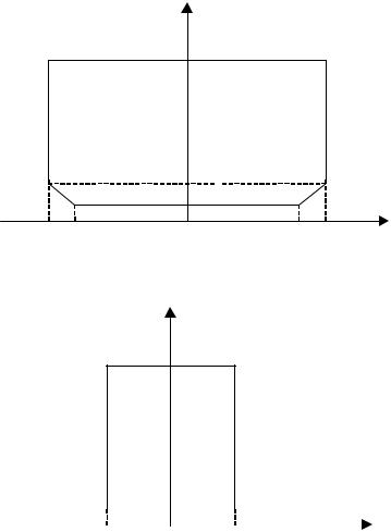
In the diagram of Specification 1.0, the area showing Unacceptable Region is missing. It should be corrected as shown below.
Intensity [mW/sr]
500 |
Unacceptable Region |
|
|
Acceptable Region |
|
(a) Host Devices
100
Unacceptable
Region 68
36
-50 |
40 |
30 |
0 |
30 |
40 |
50 |
Angle [degrees]
7

IrDA Control Errata, 1998
Intensity [mW/sr]
500 |
Unacceptable Region |
|
(b) Peripheral Type 1 Devices |
Acceptable |
Region |
|||||
|
|
|
100 |
|
|
|
|
|
|
|
Unacceptable |
|
|
|
|
|
|
|
Region |
|
|
|
|
|
|
|
|
|
|
|
|
-15 |
0 |
15 |
|
|
|||
|
|
|
Angle [degrees] |
|
|
|
|
|
|
|
Intensity [mW/sr] |
|
|
|
|
|
|
|
500 |
|
Unacceptable Region |
||
|
|
|
|
|
|
|
|
(c) Peripheral Type 2 Devices |
Acceptable |
Region |
|||||
|
|
|
9 |
|
|
|
|
Unacceptable
Region
-40 |
0 |
40 |
|
Angle [degrees] |
|
Figure 3.9 : Acceptable Intensity Region in horizontal angular range
8

IrDA Control Errata, 1998
Figure 3.10 (3.6)
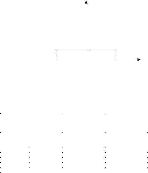
In the diagram of Specification 1.0, the area showing Necessary Region is wrong. It should be corrected as shown below.
Irradiance [μW/cm2]
Undefined Region 1250
Necessary Region
(a) Host Devices
1.111
0.400
-50 40 0 40 50 Angle [degrees]
Irradiance [μW/cm2]
Undefined Region 1250
|
Necessary |
(b) Peripheral Type 1 Devices |
Region |
|
|
0.400 |
|
|
|
|
|
||
-15 |
0 |
15 |
||
|
|
Angle [degrees] |
|
|
9

IrDA Control Errata, 1998
|
|
|
Irradiance [μW/cm2] |
|
|
||
|
Undefined Region |
|
1250 |
|
|
||
|
|
|
|
||||
|
|
|
|
|
|
|
|
|
|
|
Necessary |
|
|
|
|
(c) Peripheral Type 2 Devices |
|
Region |
|
|
|
|
|
|
|
|
|
|
3.0 |
|
|
|
|
|
|
|
|
||
-40 |
|
0 |
40 |
||||
|
|
|
Angle [degrees] |
|
|
||
Figure 3.10 : Necessary Irradiance Region in horizontal angular range
Table 4.1(4.1)
The table of Specification 1.0 has unnecessary ruled-lines. It should be corrected as shown below.
|
|
|
F r om H o s t t o |
F r om P e r i p h e r a l t o |
|
H o s t S t a t u s |
P e r i p h e r a l |
H o s t |
|||
( M A C p a y l o a d |
( M A C p a y l o a d |
||||
|
|
|
|||
|
|
|
l e n g t h ) |
l e n g t h ) |
|
To un e n u m e r a t e d p e r i p h e r a l s |
S h or t ( 0 - 9 b y t e s ) |
S h or t ( 0 - 9 b y t e s ) |
|||
|
|
|
|
||
To un b ou n d p e r i p h e r a l s in |
S h or t ( 0 - 9 b y t e s ) |
S h or t ( 0 - 9 b y t e s ) |
|||
M o d e - 1 / 2 |
|
|
|
||
|
|
|
|
|
|
|
|
M o d e - 0 |
- |
S h or t ( 0 - 9 b y t e s ) |
|
To bou n d |
|
|
|
|
|
|
|
S h or t ( 0 - 9 b y t e s ) |
S h or t ( 0 - 9 b y t e s ) |
||
p e r i p h e r a l s |
|
M o d e - 1 |
|
|
|
|
S h or t ( 0 - 9 b y t e s ) |
L on g ( 0 - 9 7 b y t e s ) |
|||
|
|
|
|
|
|
|
|
|
L on g ( 0 - 9 7 b y t e s ) |
S h or t ( 0 - 9 b y t e s ) |
|
|
|
|
|
|
|
|
|
M o d e - 2 |
S h or t ( 0 - 9 b y t e s ) |
S h or t ( 0 - 9 b y t e s ) |
|
|
|
|
|
|
|
Table 4.1 Possible Short/Long frame combination
10
