

Design and characterization of flexible circuit for disk drive application
.pdfDesign and Characterization of Flex On Suspension (FOS) Circuit for HDD Head Gimbal Assembly
Design Challenges
Fundamental Problem - To read and write smaller bits or write bits faster (at GHz rate)
Current Suspension Design Improvements - Reduce Track Pitch, Improve Positioning Accuracy
Design Constraints : |
CONNECTION TO |
GMR HEAD SLIDER |
1.) Mechanical |
PREAMP |
ASSEMBLY |
|
|
2.) Process Capability
3.) Electrical
FLEX ON SUSPENSION (FOS)

Design Guidelines
1.) Mechanical
- Stiffness of HGA: minimize in Gimbal region. Why? Improve Compliance in HGA during flight. How? - reduce trace thickness. Effects? - Circuit Impedance
2.) Process Capability
- 3M design guidelines : 25 microns tracewidth and spacing
3.) Electrical
- Driver chip output impedance and GMR head impedance : controlled impedance throughout flex circuit
GMR HEAD
DISK
FLEX

Electrical Analysis of Flex
Objective : To reduce design cycle time
To achieve fastest time to market
Requirement : Short, well defined current transitions from Write Driver to Write Coil. Write Coil excited by large dI/dt. Any abrupt changes in impedance especially inductance distort the signal shape or attenuation by reflections. The same applies to the Read channel.
Verification : Test and Measurement methodology. Impedance profile along the flex circuit. Time domain measurements such as impedance and crosstalk using Time Domain Reflectometry (TDR) instrumentation.

TDR Measurement Setup
Time Domain Reflectometry - High speed digitizing oscilloscope with a built-in step generator capable of launching fast edge into a device under test (DUT)
Function and Outputs - Monitor reflected wave from various discontinuities in the DUT. Identify areas along DUT contributing excessive inductances and capacitances.
Ei Er
TDR
LOAD
DUT
Step Output - 35ps, 400mV

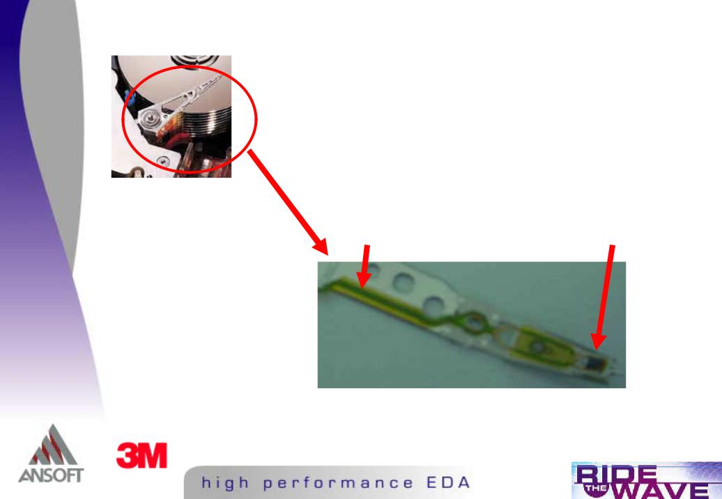
Flex Circuit Structure
Total structure length = 52mm
PRE-AMP
GIMBAL
BODY |
SWAGE PLATE |
|
Virtual TDR using Ansoft Spicelink
DIVIDE and CONQUER
"Identify each and every unique 2 Dimensional cross sections
"Perform Resistance, Inductance, Capacitance, Conductance 2D extraction using Ansoft’s SI2D parasitic extractor
"Create Spice Equivalent Circuit for each and every unique section
"Sitch all subcircuits in Ansoft’s Schematic Capture and perform Time Domain Simulations

Differential Signaling
"2 signals are transmitted between preamplifier and the GMR head : READ and WRITE
"Differential System
"responds only to potential difference between its balanced input teminals
"suppress outputs from common mode voltages - better noise immunity
" inputs must be balanced |
READ pair WRITE pair |
|

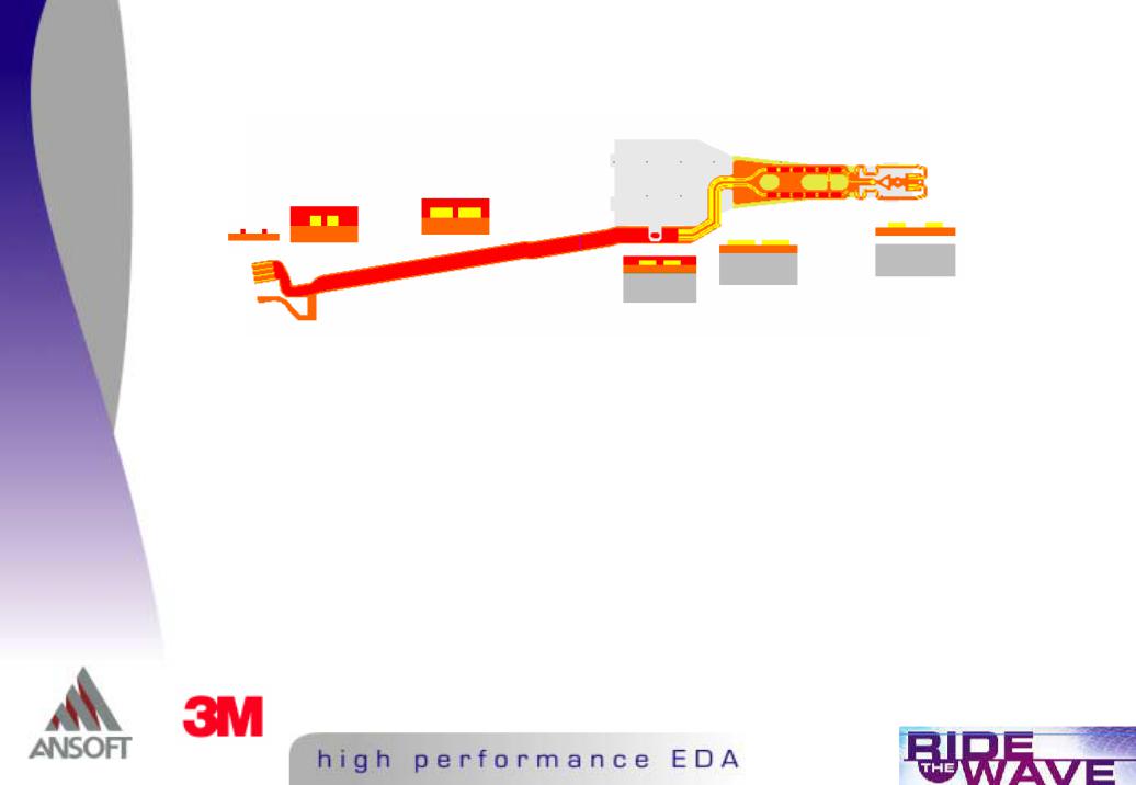
Unique HGA Cross Sections
Covercoat
 Copper Traces
Substrate
Adhesive
Steel
SI 2D
For illustration purposes, extraction was done for the Write signal pair, a similar extraction was done for the Read pair
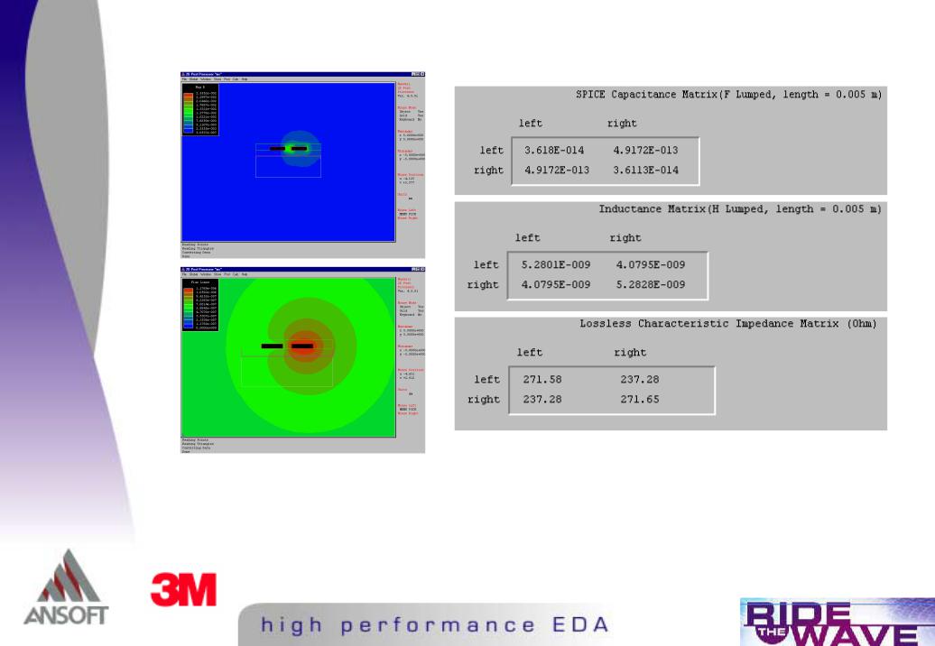
R, L, C, G Extractions and Field Plots
V1 |
= Z11I1 |
+ Z12I2 |
Zodd = (Z11 |
- Z12) |
Zdiff = 2 x (Z11 - Z12) |
V2 = Z21I1 |
+ Z22I2 |
Zeven = (Z11 |
+ Z12) |
|
|