

Design of an active acoustic sensor system for an autonomous underwater vehicle
.pdfAppendix A: The Time Processor Unit
A.1 Channel Control
Function |
Host service |
Host Sequence code |
|
code |
request code |
|
|
0xA |
1 = Initialise channel |
0 = No link, single capture |
|
|
|
1 |
= No link, continuous |
|
|
2 |
= Link channels, single capture |
|
|
4 |
= Link channels, continuous |
Table A.1: TPU code options [22]
•The interrupt enable must be set to 1 if the TPU channel is to interrupt the CPU
•The interrupt status register indicates when an interrupt has occurred for the channel and does not need to be set
•The channel priority register is the register that begins operations for the channel and must be set last. The code for it determines the priority at which it is serviced by the TPU. This ranges from 0 to 4. If the register is zero, this means the channel is not on.
Apart from the interrupt status register, all the registers need to be set before the channel can operate properly.
87
Design of an Active Acoustic Sensor System
A.2 Parameter RAM
The following is what is required in the parameter RAM in order to allow the ITC function to operate properly.
Parameter |
Value |
Meaning |
Inputs: |
|
|
CHANNEL_CONTROL |
|
|
Bits[1:0] |
{11} |
Input channel |
Bits[4:2] |
{000} |
Do not detect transition |
|
{001} |
Trigger on rising edge |
|
{010} |
Trigger on falling edge |
|
{011} |
Trigger on either edge |
Bits[8:5] |
{00xx} |
Timer on input channel |
|
{000x} |
Reference timer 1 |
|
{001x} |
Reference timer 2 |
MAX_COUNT |
0 < N ≤ 0xFFFF |
Number of events to count |
Table A.2: Parameter RAM for ITC [22]
88

Appendix B: The Timer Frequencies
The table defines the possible clock frequencies that are available to the timer used for the TPU [Harman, 1991]. This is based on a 16.78MHz system clock. The resolution is the clock signal’s period used for clocking the timer. As the distances for the echo sounder range exceed the 5m to 10m range boundary set for the project, the time range may also need to increase. This will mean that the resolution will not be as fine. The 31.25ms range will be necessary when the distance range is between 11.7m and 23.4m.
Frequency |
Resolution |
Range |
4.19MHz |
238.4ns |
15.6ms |
2.097MHz |
476.8ns |
31.25ms |
1.049MHz |
953.7ns |
62.5ms |
0.524MHz |
1.91µs |
125ms |
262.1kHz |
3.81µs |
0.25s |
131.1kHz |
7.63µs |
0.5s |
65.53kHz |
15.3µs |
1.0s |
Table B.1: List of TPU timer frequencies, and corresponding resolutions and ranges [22]
89

Appendix C: Passive Sonar Application
The possibility of being able the convert the active sonar unit to a passive sonar unit, by blanking out the transmitter, enables the development of passive sonar applications. The main use for passive sonar is the detection of a sound source underwater. The advantages for this approach are:
•The sensor can detect a sound source from twice the distance that an active sonar unit can, due to the fact that the signal must be sent out and reflected before it is detected, reducing the range of the active sonar. This is assuming the same signal intensity is transmitted from both.
•The location of the sensor cannot be discovered when using passive sonar, because the sensor does not emit a sound. When a sensor emits a sound, it is possible to locate the sensor using an array of passive sonar. This is why passive sonar is used in the military.
It is, therefore, beneficial to research passive sonar detection.
C.1 Time Delay Estimations
The main method of detecting the DOA of a signal is by using the time delays between sensors and the geometry of the sensors to triangulate the DOA. With the use of a system, implemented with sensors similar to the ones for this project, it is easy to determine an approximate time delay between sensors.
In order to triangulate the DOA of a signal in 3 dimensions, 3 time delays are required. This will mean that at least 3 sensors will need to be placed in the array. However, the arrangement of 3 sensors means that the sensors will have to be timing continually as there is no way of determining when a signal will be approaching.
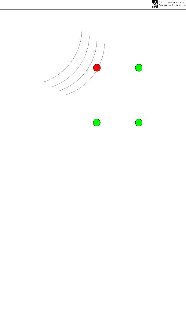
A much more effective method is to use four sensors. This system will rely on a trigger system to activate the sonar array. Initially, also the sensors will be set to detect a signal of the correct frequency. This will not require any CPU processing time as the TPU is a separate module from the CPU on the Motorola 68332 microcontroller. Once a signal impinges on the first sensor in the array, the three other sensors’ timers are triggered, using the linking capabilities of the TPU channels, to determine how long it takes for the signal to arrive at
91
Design of an Active Acoustic Sensor System
each individual sensor. This is shown in Figure C.1. The red sensor is the sensor that detects the signal, and the other three green ones must time how long it takes for the signal to arrive.
Figure C.1: Signal impinging on the first sensor of passive array
For a much more robust method of detecting the time delays between sensors, a digital signal processor (DSP) is required. The method behind this is to digitalise the signal that is being received by the sensors. It is accomplished by using an ADC.
The digitalised signal is then sent to the central processor where the signal is cross correlated with a neighbouring sensor’s signal to determine the time delay between the two sensors. A cross correlation is a function that reaches its maximum value when the phase or time delay between two signals is matched. To perform a cross correlation on two signal sequences, the best approach is to perform a fast Fourier transform (FFT) on both of them, multiply the sequences together and then inverse FFT the resultant sequence [2], as this is computationally less expensive.
Rxy (λ)= |
1 |
N − |
|
λ |
|
−1 |
|
|
|
|
|
||||||
∑x(k )y(k + λ) |
|
|||||||
N |
|
|||||||
|
k =0 |
|
||||||
= |
1 |
F −1 [X * (f )Y (f )] |
(C.1) |
|||||
N |
||||||||
|
|
|
|
|
|
|
||
Rxy (λ)= |
1 |
F −1 [F[x(k )]F[y(k )]] |
|
|||||
N |
|
|||||||
|
|
|
|
|
|
|
||
By analysing the resultant cross correlation sequence for the maximum value, the time delay between the two sensors is discovered.
92

Appendix C Passive Sonar Detection
This method is far more robust then the first method, that uses the echo sounder as a receiver to detect time delays, because this can be used when the SNR at the sensors is not very high. The cross correlation give the best estimate of the time delay in a noisy environment, whereas the echo sounder receiver will not be able to detect the signal and thus cannot provide a TDE for noisy environments. This does come at a cost as the DSP systems are much more expensive and difficult to build.
C.2 Direction of Arrival Calculation
Once the TDEs are determined for the sensor array, then the DOA can be calculated, using the TDEs and the geometry of the sensors.
The time delay direction finding (TDDF) algorithm by Berdugo et al [4] is the easiest method for determining the DOA.
Now the sensor positions can be represented by:
ri = [xi yi zi ]
The differential time delays can be placed in a vector:
r |
τ |
12 |
|
|
|
|
|
≡τ j −τi |
|
τ = τ13 |
;τij |
|||
|
τ |
14 |
|
|
|
|
|
|
|
And the DOA vector is:
r |
kx |
sinθ cosφ |
|||
|
|
|
|
|
|
k |
= ky |
= sinθ sin φ |
|||
|
|
|
|
cosθ |
|
|
kz |
|
|
||
(C.2)
(C.3)
(C.4)
The time delay between two sensors can be determined as the projection of the distance vector between the two sensors onto the incoming wave vector, k, divided by the speed of sound, c.
r |
|
r |
rr |
− rr |
|
|
|
|
Rk |
r2 |
r1 |
|
|
||
τ |
= − |
|
; R ≡ r3 |
− r1 |
|
(C.5) |
|
c |
|||||||
|
|
r |
r |
|
|
||
|
|
|
r4 |
− r1 |
|
|
93

Design of an Active Acoustic Sensor System
The main approach to this method is to attempt to find the DOA vector that will minimise the error, ε, between the estimated time difference and the predicted time difference. This can be accomplished via a least squares error method.
|
|
|
ˆ |
|
|
|
|
εr = |
R × k |
+τrˆ |
(C.6) |
|
|
c |
|||
|
|
|
|
|
|
ˆ |
rˆ |
|
|
|
|
Where R |
and τ |
are the estimated values of the distance vector and the time difference vector, |
|||
respectively.
From the DOA vector, it is simple to determine the azimuthal angle, φ, and the elevation angle, θ.
kx |
= sinθ cosφ |
|
|||
ky |
= sinθ sinφ |
|
|||
ky |
= |
sinφ |
= tanφ |
(C.7) |
|
kx |
cosφ |
||||
|
|
||||
ˆ
φˆ = tan−1 kˆykx
kz = cos θ |
(C.8) |
θˆ = cos −1 (kz ) |
|
94

Appendix D: The Contents of the CD
D.1 The Thesis
Copies of the thesis have been stored as Word and PDF documents
D.2 The Pictures and Drawings
All the pictures used specifically for the sonar component of the AUV is included in this file
D.3 The Code Set
The code on the CD has been sorted out into three lots. The different sections represent the three different stages of coding in this project. They are:
•Testing the Navman Depth 2100 echo sounder
•Testing and verification of the prototype echo sounder hardware
•Final code of the prototype echo sounder and dynamic testing
D.4 The Datasheets and Research
Datasheets, including one for the LM1812 ultrasonic transceiver chip, have been included as well as research documents that may be useful for future research. These are stored in PDF format.
95