

EIA-364-109 standard.Loop inductance measurement test procedure for electrical connectors
.pdfEIA-364-109
Page D-4
Figure D.1 – Example of mutual inductance coupling coefficient measurement setup
EIA-364-109
Page D-5
E. Loop, Mutual, and Self Inductance (Informative)
E.1 Annex provides a general overview of the differences between loop inductance, mutual inductance, and self inductance. Although this particular test method pertains specifically to loop inductance (in the range of 1 nH to 10 nH), it is important to understand the differences between all three inductance parameters as they are tightly related, both physically and mathematically, but describe different properties of conductors.
E.2 As an alternating current flows through a conductor (i.e., a terminal in an interconnect), the current causes a magnetic field or magnetic flux around the conductor. This magnetic property of a conductor, can be described by the electrical parameter inductance. The term inductance is used to describe the property of a conductor or circuit element that opposes the change in current flow. Inductance causes current changes to lag behind voltage changes, and is measured in units of Henries (Webers/Amp). The following brief descriptions are provided to distinguish the difference between several different ‘types’ of inductances that are used to describe the electrical characteristics of conductors and interconnects.
E.3 Interconnects (and other circuit constructions) are typically characterized by three different types of inductances; loop inductance, self inductance, and mutual inductance. Although other ‘types’ of inductances can be used, i.e., internal inductance (used for material characterization in electromagnetic field theory), and partial inductance (used for theoretical calculations and analytical modeling techniques), only the loop inductance, self inductance and mutual inductance parameters will be discussed here. Also, although all three of these inductances are related both physically and mathematically to each other (as will be shown), they each have significantly different meanings, and their values describe significantly different characteristics of the interconnect (or circuit element). When specifying or reporting an inductance value for an interconnect, one should be careful to clearly define which ‘type’ of inductance is being referenced.
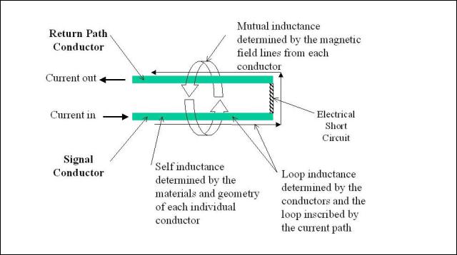
E.4 These specific inductances, loop, self, and mutual, can be better described if we consider two conductors, i.e., a pair of terminals within an interconnect. One of the conductors is the signal terminal, and the other conductor is the return path terminal for the noted signal. Current is fed into the signal terminal, and creates a magnetic field around that conductor. Also, this current is returned through the return terminal, and creates another magnetic field around the return path conductor. It is this conductor arrangement and current path convention, as shown in figure E.1, which will be used to describe the inductance parameters noted.
E.5 The loop inductance parameter is most typically used to characterize interconnect performance, and can provide a representation of the intended application performance. This is due to the fact that the signal and return path currents, mutual inductances, and terminal self inductances are taken into consideration for the measurement. Although, other types of inductance measurements and parameters are important and can be very useful, it is typically the loop inductance that can most readily be directly measured.
EIA-364-109
Page D-6
Figure E.1 - Conductor arrangement and current path convention for description of inductance
E.6 As noted above, all three of these inductances are related mathematically as shown in the following equation:
LLoop = L1 + L2 ±(2 Lm )
where: L1 = self inductance of the driven conductor
L2 = self inductance of the return path conductor(s)
Lm = mutual inductance between the drive and return path conductors.
E.7 The ± symbol in the above equation is used to take into account the relative direction in which the currents in the terminals are traveling. The minus sign is used for the case when the currents are traveling in opposite directions. The plus sign (which is not used specifically in this test method) is used for the case when the currents are traveling in the same direction. This equation demonstrates that for currents traveling in opposite directions, the overall loop inductance is actually decreased as the mutual inductance is increased. However, for currents traveling in the same direction, as the mutual inductance is increased, the overall loop inductance is also increased. This effect should be noted, and reviewed while tests are conducted as the current direction and return paths will have significant effects on the overall loop inductance measured value.
EIA-364-109
Page D-7
E.8 In contrast to loop inductance, the self inductance parameter is used to describe the inductance of a single conductor, ideally in free space. Self inductance of a single conductor is based on the material properties and geometry of the conductor and does not take into consideration materials around the conductor or other conductors or currents. Self inductance is also a very important circuit parameter, and can be used for simulations and calculations effectively when the value is known. However, self inductance in ranges below approximately 20 nH (a range covering many electrical connectors and sockets) is very difficult to measure due to practical limitations of test equipment, calibration structures, and test fixtures. Some of the main issues with obtaining an empirical, accurate measurement of self inductance in this range include:
obtaining an ideal short over a distance in which the inductance of the short can be considered zero,
obtaining test equipment in which the resolution would allow measurements to be made accurately at 1-20 nH,
providing a test fixture in which fixture test currents are not allowed to interact with the conductor or terminal being tested.
E.9 However, with the use of both modeling techniques and measurement data, self inductance can be calculated from the above equation utilizing the measurement data and the calculated data.
E.10 Mutual inductance is also an important circuit parameter, and effects the loop inductance and thus the performance of an interconnect. Mutual inductance is related to the magnetic field interactions that are generated by currents flowing in two or more conductors. Mutual inductance is determined by the materials and geometries of the entire current path structure including both the conductors and the areas surrounding the conductors. Therefore, mutual inductance is very tightly related to the loop inductance and self inductance parameters described above. Again, as seen in the loop inductance equation, the self inductance of the terminals can remain the same, and by either increasing or decreasing the mutual inductance between the terminals, the loop inductance can be changed.
E.10.1 The test professional should be aware of these potential changes during the inductance measurement. Due to the fact that mutual inductance is a function of the magnetic fields, which are generated by current flowing in the conductors, care should be taken to minimize the interaction between the test fixture and the specimen. More specifically, the magnetic field interactions generated as a result of the current in the test fixtures, should be reviewed as it can have significant effects on the measurement.
E.10.2 Similar to the reasons given for making a low level self inductance measurement, the mutual inductance parameter is also very difficult to measure in such low values as are encountered in typical electrical interconnects. As an example, for typical board to board or edge card type connectors, the mutual inductance parameter may be approximately 10% - 15% of the loop inductance value. However, again similar to self inductance, mutual inductance can be calculated from the a combination of measurement data (typically the loop inductance) and calculations or modeling by using the loop inductance equation.

EIA-364-109
Page D-8
EIA Document Improvement Proposal
If in the review or use of this document, a potential change is made evident for safety, health or technical reasons, please fill in the appropriate information below and mail or FAX to:
|
|
Electronic Industries Alliance |
|||
|
|
Technology Strategy & Standards Department – Publications Office |
|||
|
|
2500 Wilson Blvd. |
|||
|
|
Arlington, VA 22201 |
|||
|
|
FAX: (703) 907-7501 |
|||
|
|
|
|
|
|
Document No. |
|
Document Title: |
|||
|
|
|
|
|
|
Submitter’s Name: |
|
Telephone No.: |
|||
|
|
|
FAX No.: |
||
|
|
|
e-mail: |
||
|
|
|
|
|
|
Address: |
|
|
|
|
|
|
|
|
|
|
|
|
|
|
|
|
|
Urgency of Change: |
|
|
|
|
|
Immediate: |
|
At next revision: |
|
|
|
|
|
|
|||
|
|
|
|
|
|
Problem Area:
a.Clause Number and/or Drawing:
b.Recommended Changes:
c.Reason/Rationale for Recommendation:
Additional Remarks:
Signature: |
Date: |
|
|
FOR EIA USE ONLY
Responsible Committee:
Chairman:
Date comments forwarded to Committee Chairman:

EIA-364-109
Page D-9