

Embedded system engineering magazine 2006.07,08
.pdfX-Ray vision for your designs
Discover ease of use with agilent digital debug tools
Agilent 1680 Logic Analyser
Agilent Logic Analysers Family
•Designed for occasional users and digital experts
•Fast Scope correlation with LAN cable
•Flying leads available up to 1.5 Gb/s
From the Agilent 1690AD Firewire PC plug-in logic analyser family to the 16900 modular family, you can experience exceptional ease of use, triggering and analysis capabilities.
Choose between a broad range of flexible probing solutions that will help you to resolve your tough signal integrity issues. Our ViewScope feature allows you to use a simple LAN cable to ensure ultra-fast oscilloscope waveform data import and global marker correlation with your logic analyser. You can also access 64 signals through a single FPGA debug pin thanks to the Agilent FPGA Dynamic Probe.
To see how our logic analysers, probing and application solutions save you time debugging your digital system, view product demos at www.agilent.com/find/logicdemos or call UK 07004-666 666 for more information
© Agilent Technologies, Inc. 2006

<News - Boards>
ESE Magazine July/August 06
Boards
VME SBC
CONCURRENT Technologies’ VP33x/02x family is a range of high performance, low power VME single board computers. Processors range from the 1.0 GHz Celeron M ULV 373 processor up to the 1.8 GHz Pentium M 745. These RoHS compliant boards are for a broad range of commercial applications and extended temperature options are available over -40°C to +85°C or over -25°C to +70°C. Applications are expected to be within
the defence, security, telemetry, industrial control, scientific, and aerospace markets.
www.gocct.com
ETX 3.0 Standard
NINE COMPANIES are signed up to support the new 3.0 Specification of the ETX Computer-on- Module Standard. The newest members of the ETX Industrial Group are Arbor, Axiomtek and Blue Chip Technology. A downloadable version of the specification will be available soon.
www.etx-ig.org
Tools for Advanced TCA
HARTING has introduced a set of press-in tools for AdvancedMC Type B+ connectors for AdvancedTCA applications. The tools are designed for different specifications of connector: both with and without pegs.
www.harting.com
For a more detailed look at these stories please visit
www.esemagazine.com
Explosion-proof display
Kontron’s Triton D1 computing display carries the Certified Class l Zone l / ATEX Zone l and electrical protection class EMC/EN61326 for maximum protection in hazardous-classified areas. for oil and gas industry services companies, the Triton D1 also carries both the Class I, Zone I, Ex d IIB T4 and Class I, Zone l, AEx d IIB T4 certifications in the United States and Canada and the ATEX II 2 G, EEx d IIB T4 certificate in Europe.
The Triton D1 modular construction with a flameproof all-machined aluminium enclosure
has easily serviceable subassembly units that greatly shorten repair time. It has a 15-inch full sunlight viewable display with EnhancedInfrared touch screen technology decoupled from the LCD and incorporating bullet-proof glass.
www.kontron-emea.com.
duction-cooled configurations.
Software board support packages and support for real-time operating environments, such as VxWorks will be announced soon.
www.cwcembedded.com.
Migration to CompactPCI Express
Schroff has introduced a new hybrid backplane that combines CompactPCI and the
new CompactPCI Express bus architectures on to a single backplane.
Core Duo
CompactPCI SBC
Curtiss-Wright has announced the S/DCP31201, a 3U CompactPCI SBC with Intel’s 1.67 GHz Core Duo processor. It is designed for
defence and aerospace platforms SWaP (Size, Weight, and Power) cal. The S/DCP3-1201 can be with either Intel Core Duo or CPUs, and is available in both
Character modules
THE NEW RANGE of colour character modules from Optrex include an extended operating temperature range from -20 - +70°C making them suitable for many working environments, an internal black mask to improve contrast and legibility. They are available in a wide variety of colours / industry standard configurations with compatibility with existing Optrex modules. All modules are RoHS compliant.
www.apollodisplays.co.uk
12

COTS FPGA boards
Nallatech has expanded its Xilinx Virtex-4 based range with three new COTS FPGA solutions.
The new products are the BenNUEY PCI-104- V4, a PCI-104 form factor computing stack, and two daughterboards, the BenIO-V4 and the BenADDA-V4. BenIO-V4 provides 152 digital IO lines, whilst the new BenADDA module delivers dual 105 MSPS ADC and dual 160 MSPS DAC
capabilities. They are for the wide range of processing needs of the military and aerospace markets and complement the existing Nallatech Virtex-4 based FPGA products.
www.nallatech.com
RoHS video capture cards
IEI has two RoHS compliant 4 channel video capture cards, the IVC100G-RS and IVC200G-RS with auto-sense input and multi screen support, designed for cost conscious applications in the security, surveillance or in DVR applications.
The IVC-200G-RS will capture 120 frames per second (fps) at a resolution of 720x576 (PAL) across each of the four channels, while the IVC-100G-RS will capture 30fps. Both boards capture composite video via a BNC input with auto sensing on the input to sense NTSC, PAL or Secam video.
A full set of Windows and Linux drivers is available.
www.wordsworth.co.uk
Power module
Tyco has launched an innovative Power Module package with 90° mounting angle
for inverter applications that require the heat sink to be in an upright position in respect to the PCB.
The flow90PACK 1 family (IGBT 6 pack) is available both for 600V (up to 75A) and 1200V (up to 35A).
www.em.tycoelectronics.com.
DIN-Rail DC UPS
PULS’ new UB10.241 DC UPS DIN-Rail power supply provides protection for 24V DC systems.
Under normal operation the system power supply charges the UPS 12V battery. Should the supply voltage drop or be disconnected, the battery voltage is boosted to 24V via the UPS and supplied to the load as a regulated power source. A matching DIN-Rail battery module, the UKZ12.07 has a 12V 7AH maintenance free lead acid battery with on board fuse protection and connecting cables.
UPS output current is 10A continuous and 15A for 5 seconds peak and the operating temperature range is –25 to +60°C without derating.
www.puls.co.uk
</News - Boards>
</Feature>
ESE Magazine July/August 06
14
SysML hits the home straight
<Written by> Matthew Hause, Principal Consultant, ARTiSAN Software Tools </W>
SysML is about to be adopted as a formal industry standard by the Object Management Group.
SySML is a visual modelling language that extends UML 2 in order to support the specification, analysis, design, verification and validation of complex sys-
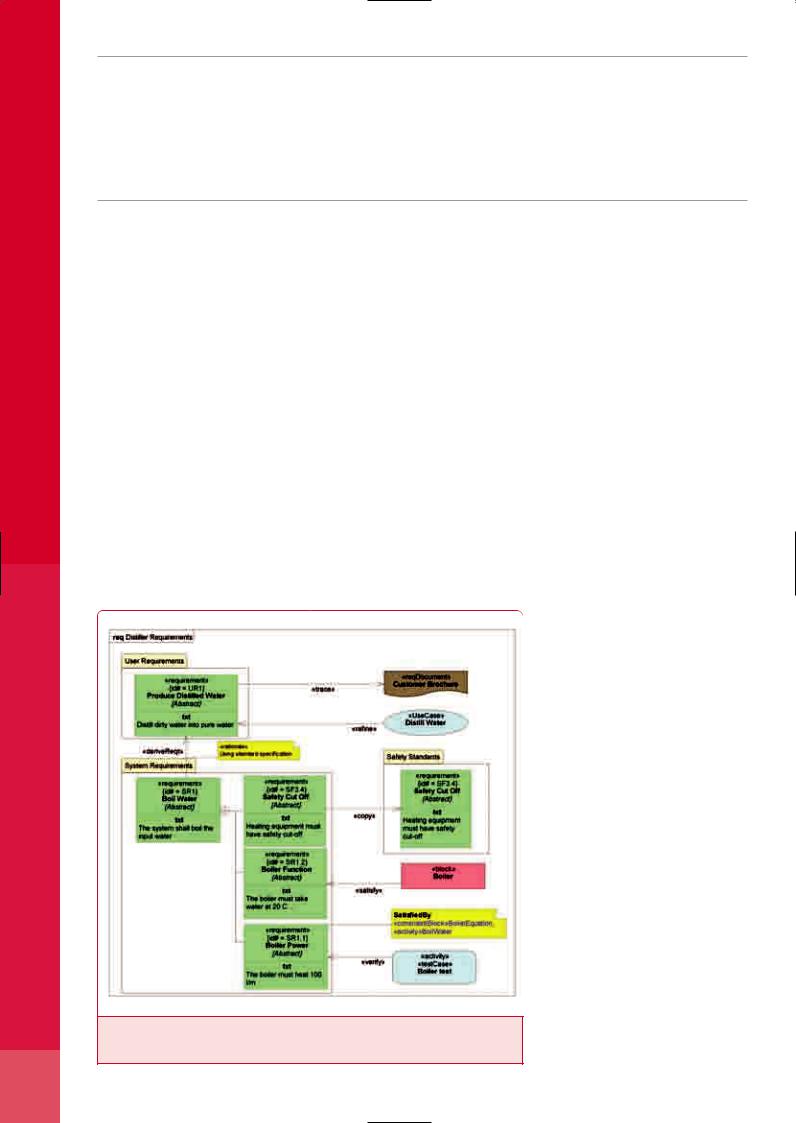
a requirement into its constituent requirements. A requirement is related to other key modelling artefacts via a set of stereotyped dependencies. The «deriveReqt» and «satisfy» dependencies
are operational, functional, interface, control, performance, physical and storage requirements. These stereotypes may restrict the types of model elements that can satisfy or refine the requirement. The requirements model can be shown in a graphical, tree structure, or tabular format. Figure 1 shows the graphical format - a Requirements Diagram.
Figure 1: Requirements diagram for a distillation system: on the left a user requirement Produce Distilled Water uses the «deriveReqt» dependency to create a system requirement, Boil Water.
Blocks
Block is a general purpose hierarchical structuring mechanism that abstracts away much of the software-specific detail implicit in UML structured classes. Blocks can represent any level of the system hierarchy, including the top-level system, a subsystem, or logical or physical component of a system or environment. A SysML Block describes a system as a collection of parts and connections between them that enable communication and other forms of interrelationship. Ports are a special part providing access to internal structure when the block is used within a larger structure although, unlike UML, “deepnested” connectors can be drawn directly to internal elements if required to describe physical systems, which are not simple black bodies. There are two ports: Service Ports support client-server communication and Flow Ports define flows into or out of a block.
Two diagrams describe block relationships, the Block Definition Diagram (BDD), similar to a traditional class diagram, describes relationships that exist between blocks; the Internal Block Diagram (IBD) describes block internals. (Fig.2)
Parametric Models
Parametric models describe system properties and their interrelationships and are supported by the SysML ConstraintBlock. It defines a set of parameters and one or more expressions stating how a change to the value of one parameter impacts the value of other parameters. By default, these parameters are non-directional and so have no notion of causality. ConstraintBlocks are then bound via their parameters to system properties to enforce system constraints: new ConstraintBlocks can be built by reusing more primitive ConstraintBlocks such as basic mathematical operators.
SysML also defines a model of value types that can take units and dimensions; these value types can then be used to type parameters in

parametric models.
ConstraintBlocks may be used to express mathematical equations, such as ‘F=m*a’ and ‘a = dv/dt’, statistical values or utility functions.
The Parametric Diagram (Fig. 3) is a specialised variant of an internal block diagram that restricts diagram elements to represent constraint blocks, their parameters and the block properties that they bind to. Both parameters and properties may be represented as small “pin-like” boxes to help make the diagrams more scaleable.
Continuous systems
Additionally, SysML provides extensions to activities to describe the distributed flow of material, energy, or information through a system. These extensions allow the modeller to impose restrictions on the rate at which items flow along edges in an activity, or in and out of parameters of behaviours. Discrete and continuous flows are unified under rate of flow, as is traditionally done in mathematical
models of continuous change. |
<End/> |
www.artisansw.com |
|
Figure 2: Internal Block Diagram for distiller
Figure 3: Parametric diagram: the constraints on fluid flow through the Distiller block. The nodes on the right represent item flows (Fig. 2). The five constraints show how the parameters of the various generic and specific equations bind to properties of the item flows to enforce the flow constraints. Some of the equations are shown as attached notes although a compartment in the constraint symbol may also be shown. Note that the flow properties have types with defined units.
for perfect system integration
what really counts is:
teamwork
One supplier, one manufacturer, one quality standard. The complete electronic know-how from Rittal – reliably available systems up to level 5.
With innovative components for AdvancedTCA and MicroTCA:
•Case solutions in 5, 12, 13 U or cube design
•High-speed backplanes up to 10 Gbit/s
•Climate control concepts up to 200 W/board and more
•Variable shelf management concepts
Everything fully assembled, ready to run and individually configured. And also CompactPCI, VME and VME64x.
As the leading system supplier, Rittal is able to promise all-inclusive competence – worldwide.
RITTAL Electronic Systems – the complete know-how.
Rittal Limited, Braithwell Way, Hellaby Industrial Estate, Rotherham, S Yorks S66 8QY
Tel.: 01709 704000 – Email: information@rittal.co.uk. www.rittal.co.uk
®

</Feature>
Modelling in Eclipse
<Written by>Stephen Mellor, Chief Scientist, Mentor Graphics'Embedded Systems Division </W>
UML combined with Eclipse provides a framework for modelling both structure and behaviour
HE ECLIPSE FRAMEWORK sup- |
managers for editing, compiling, and linking; |
often they each use different interfaces, con- |
ports plug-ins for a wide range of |
profilers for system performance profiling and |
ventions, and paradigms. The cognitive disso- |
software construction tools, from |
analysis of RTOS and user events; debuggers |
nance caused by switching between tools can |
Tmodelling to code debugging. These |
spanning targets from workstations to embed- |
become acute, especially as we lengthen the |
tool chain to include modelling. |
||
|
|
Open Platform |
ESE Magazine July/August 06
Figure 2: Debugging a microwave oven.
16
developers may construct plug-ins to Eclipse to load and unload models, or to gain access to other services, such as revision management systems and comparison tools.
Eclipse plug-ins inherit from framework classes so the look and feel for the tools in the tool chain are consistent. The editors, views, and user-interface idioms all work together to make a smooth transition from modelling down to debugging the code on the target. Setting breakpoints is the same whether you set a breakpoint on access to a model element or on a line of code. Similarly, stepping through the model or the code uses the same hot keys and behaves in the same way.
Hold up. Stepping through the model? Setting a breakpoint on access to a model element?
Yes, the UML is executable, or at least parts of it are. In addition to modelling software structure, UML can be used for modelling behaviour that can be translated into any language, from small footprint C to C++. While all parts of UML can be used (use cases,

... a model can even be interpreted or translated into hardware....
Brilliant View
with Flatpanel Controllers from Kontron
|
|
|
-7 |
|
|
CD |
|
|
oL |
|
|
Tt |
|
|
|
CR |
|
|
|
|
|
|
|
|
|
-6 |
|
|
|
|
|
D |
|
|
|
|
|
C |
|
|
|
|
|
L |
|
|
|
|
|
to |
|
|
|
|
|
T |
|
|
|
|
|
R |
|
|
|
|
|
|
C |
|
|
|
|
|
|
|
|
|
|
-5 |
|
|
|
D |
|
|
|
LC |
|
|
|
o |
|
|
|
Tt |
|
|
|
|
CR |
|
|
|
|
|
owners |
|
|
respective |
|
|
their |
|
|
of |
|
|
or registered trademarks are the property |
June 30th, 2006. Rev. #G045uk02 |
|
all other trademarks |
compliant latest by |
|
Kontron logo and |
be lead-free/RoHS |
|
the will |
|
|
AG. All rights reserved. Kontron and |
compliant logo means that product |
|
Copyright © 2006 Kontron |
and are recognized. RoHS |
|
|
|
|
|
|
a - series –
the new generation !
Easiest way to connect CRT-, DVI-, Videoand TV-Sources (incl. Component YPbPr) to a Flat Panel (TTL, LVDS)
Resolutions from QVGA up to WUXGA incl. HDTV (1080i und 720p @ 50 Hz)
Incl. powerful software tools (KCWB) via serial port interface
Plug & Display with individual flat panel adaptation via panel file incl. special video mode support
First class image quality incl. high end scaling & adaptive motion deinterlacing
Backlight dimming support (incl. PWM and light sensor support)
Extension boards e.g. for TV-tuner
Unbeatable price -performance ratio
Wide range of datacables for all leading flat panel types
Our info hotline: +44 1243 523500
w w w.kontron .com/ flatpanel sales - graphic@ kontron.com
If it‘s Embedded, it‘s Kontron.

<Buyer's Guide>
ESE Magazine July/August 2006
Buyer’s guide: modelling and code generation
Getting the best from this guide
Modelling and code generation are complementary methods of improving the way in which embedded products are designed. Our feature on modelling,
in this issue, puts forward the arguments from several companies’ perspectives, but in essence, starting with a model and then generating code should reduce overall project time, increase flexibility in re-engineering for later variants and provide better quality code. Previously seen as the domain of the defence and mission-critical applications, modelling is moving into high volume, fast moving sectors, such as consumer electronics.
We asked everyone we could find who was active in this area to provide product details, and the responses are here, in the form in which they were submitted. Use the product tables to identify possible areas of interest and then contact the principal or their UK disti, if they have one.
Modelling Tools
Company name
Applied Dynamics
Engenuity TechNologies Inc.
Esterel TechNologies
IAR Systems
Impulse Accelerated TechNologies, Inc.
LDRA
Mentor Graphics
MetaCase
National Instruments
Telelogic UK Ltd
TTTech Computertechnik AG
Visual Solutions Inc.
Zeligsoft
Product name |
Modelling language |
|
|
|
|
Beacon/Beacon for Simulink |
|
|
|
|
|
VAPS, VAPS XT |
UML subset, XML |
|
|
|
|
SCADE Studio/ SCADE Drive |
SCADE |
|
|
|
|
visualSTATE |
UML |
|
|
|
|
Impulse CoDeveloper |
C |
|
|
|
|
Tool Suite |
|
|
|
|
|
EDGE UML Suite |
UML |
|
|
|
|
MetaEdit+ |
Any (DSM tool) |
|
|
|
|
LabVIEW |
G (LabVIEW Gaphical Code) |
|
|
|
|
Rhapsody |
UML/SysML/DoDAF/Functional C/DSL |
|
SDL Suite |
|
|
16-32 |
|
|
16-32 |
|
|
16-32 |
|
|
16-32 |
|
|
16-32 |
|
|
|
|
|
TTP-Matlink |
MATLAB/Simulink |
|
|
|
|
VisSim |
VisSim |
|
|
|
|
Zeligsoft Component Enabler (CE) |
UML, XML |
|
|
|
|
Company sales contacts
Company name |
Sales contact name |
Sales contact e-mail |
Web site address |
Applied Dynamics |
Peter Moore |
peter@adi.com |
www.adi.com |
|
|
|
|
dSPACE |
|
|
www.dspace.de |
|
|
|
|
Engenuity Technologies Inc. |
Simon Leng |
simon.leng@engenuitytech.com |
www.engenuitytech.com |
|
|
|
|
Esterel Technologies |
Ian Hodgson |
ian.hodgson@esterel-technologies.com |
www.esterel-technologies .com |
|
|
|
|
IAR Systems |
Edward Gibbins |
info@iarsys.co.uk |
www.iar.com |
|
|
|
|
Impulse Accelerated Technologies, Inc. |
Brian Durwood |
brian.durwood@impulseC.com |
www.impulseC.com |
|
|
|
|
LDRA |
Jonathan Kelly |
jonathan.kelly@ldra.com |
www.ldra.com |
|
|
|
|
Mentor Graphics |
Sales Department |
embedded_info@mentor.com |
www.mentor.com/embedded |
|
|
|
|
MetaCase |
Martijn Iseger |
martijn@metacase.com |
http://www.metacase.com |
|
|
|
|
NuDesign Technologies, Inc. |
Shehzad Haq |
contact@ndt-inc.com |
http://www.ndt-inc.com |
|
|
|
|
National Instruments |
Tony Gibbs |
info.uk@ni.com |
ni.com/uk |
|
|
|
|
Telelogic UK Ltd |
Sophie Williams |
sophie.williams@telelogic.com |
www.telelogic.com |
|
|
|
|
TTTech Computertechnik AG |
Mr. Kurt Doppelbauer |
office@tttech.com |
www.tttech.com |
|
|
|
|
Visual Solutions Inc. |
Jim Webb |
Jim.Webb@visol.com |
www.vissim.com |
|
|
|
|
Zeligsoft |
Jennifer Steinberg |
sales@zeligsoft.com |
www.zeligsoft.com |
|
|
|
|
18

Distributors
Distributer name |
Sales contact |
E-mail address |
Web site |
Principal |
|
|
|
|
|
Adept Scientific plc |
Alastair Norman |
Alastair.Norman@adeptscience.co.uk |
www.adeptscience.co.uk |
Visual Solutions Inc. |
Applied Dymamics Ltd |
Peter Moore |
peter@adi.com |
www.adi.com |
Applied Dynamics |
Direct Insight |
Stuart Tindall |
info@directinsight.co.uk |
www.directinsight.co.uk |
Impulse Accelerated Technologies, Inc. |
dSPACE Ltd. |
Philip Clarke |
info@dspace.ltd.uk |
www.dspace.ltd.uk |
dSPACE |
Mentor Graphics UK |
Sales Department |
mentor_uk@mentor.com |
www.mentor.com |
Mentor Graphics |
Phaedrus Systems |
Chris Hills |
info@phaedsys.org |
http://www.phaedsys.org |
IAR Systems |
DDoes model include:
|
Platform |
|
Eclipse integration? |
|
Real time emulation? |
|
Multiple processors? |
|
Distributed systems? |
|
Communication events, buffers etc? |
|
Can you import legacy applications/code? |
|
RTOS/OS matching |
|
|
|
|
|
|
|
|
|
|
|
|
|
|
|
|
|
Unix/PC |
|
No |
|
λ |
|
λ |
|
λ |
|
λ |
|
λ |
|
λ |
|
|
|
|
|
|
|
|
|
|
|
|
|
|
|
|
|
PC |
|
No |
|
λ |
|
λ |
|
λ |
|
λ |
|
λ |
|
Ports to any RTOS |
|
|
|
|
|
|
|
|
|
|
|
|
|
|
|
|
|
PC/ UNIX |
|
No |
|
λ |
|
λ |
|
λ |
|
No |
|
λ |
|
λ |
|
|
|
|
|
|
|
|
|
|
|
|
|
|
|
|
|
PC |
|
No |
|
|
|
No |
|
No |
|
λ |
|
No |
|
λ |
|
|
|
|
|
|
|
|
|
|
|
|
|
|
|
|
|
Windows, Linux |
|
λ |
|
No |
|
λ |
|
λ |
|
λ |
|
λ |
|
No |
|
|
|
|
|
|
|
|
|
|
|
|
|
|
|
|
|
|
|
|
|
|
|
|
|
|
|
|
|
|
|
|
|
PC |
|
λ |
|
λ |
|
λ |
|
λ |
|
λ |
|
λ |
|
Nucleus, VxWorks, POSIX. Port to other OS |
|
|
|
|
|
|
|
|
|
|
|
|
|
|
|
|
|
Linux, Windows, OS X, HP-UX, Solaris |
|
No |
|
Execution engine model animation |
|
λ |
|
λ |
|
λ |
|
λ |
|
Any |
|
|
|
|
|
|
|
|
|
|
|
|
|
|
|
|
|
PC |
|
No |
|
λ |
|
λ |
|
λ |
|
λ |
|
λ |
|
λ |
|
|
|
|
|
|
|
|
|
|
|
|
|
|
|
|
|
PC/Linux |
|
λ |
|
λ |
|
λ |
|
λ |
|
λ |
|
λ |
|
λ |
16-32 |
|
No |
|
λ |
|
λ |
|
λ |
|
λ |
|
λ |
|
λ |
|
|
|
|
|
|
|
|
|||||||||
16-32 |
|
No |
|
λ |
|
λ |
|
λ |
|
λ |
|
λ |
|
λ |
|
|
|
|
|
|
|
|
|||||||||
16-32 |
|
λ |
|
λ |
|
λ |
|
λ |
|
λ |
|
λ |
|
λ |
|
|
|
|
|
|
|
|
|||||||||
|
|
|
|
|
|
|
|
|
|
|
|
|
|
|
|
|
PC |
|
No |
|
λ |
|
λ |
|
λ |
|
λ |
|
λ |
|
λ |
|
|
|
|
|
|
|
|
|
|
|
|
|
|
|
|
|
PC |
|
No |
|
λ |
|
No |
|
No |
|
λ |
|
λ |
|
Generated code callable by RTOS |
|
|
|
|
|
|
|
|
|
|
|
|
|
|
|
|
|
PC Windows |
|
Planned |
|
No |
|
λ |
|
λ |
|
λ |
|
λ |
|
λ |
|
|
|
|
|
|
|
|
|
|
|
|
|
|
|
|
Code generators
Company name
Applied Dynamics
dSPACE
Engenuity TechNologies Inc.
Esterel TechNologies
IAR Systems
Impulse Accelerated TechNologies, Inc.
Mentor Graphics
MetaCase
NuDesign TechNologies, Inc.
National Instruments
Telelogic UK Ltd
TTTech Computertechnik AG
Visual Solutions Inc.
Zeligsoft
Code generation product name
Beacon/Beacon for Simulink
TargetLink
VAPS, VAPS XT
SCADE KCG
visualSTATE
EDGE UML Suite
MetaEdit+ Method Workbench
NuDesign C++ SNMP Agent Studio for Embedded Systems
LabVIEW
Rhapsody
SDL Suite Code Builder
Statemate MicroC, C and Ada Code Generator
TAU/Developer
TTP-Bulid
VisSim/Embedded Controls Developer
Zeligsoft Code Generator
Source for generation |
|
Language generated (C, C++, Java etc) |
|
Support legacycode? |
|
Real time? |
Target processors |
Multiple processors? |
Eclipse integration? |
32 |
|
200 MHz |
|
λ |
|
λ |
|
λ |
|
|
|
|
|
|
|||||
|
|
|
|
λ |
|
λ |
|
λ |
|
32 or 64 |
|
600 MHz |
|
λ |
|
λ |
3 W |
|
|
16 |
|
25 MHz |
|
|
|
λ |
|
|
|
32 |
|
55 MHz |
|
λ |
|
|
500 mW |
|
|
32 |
|
1.5 GHz |
|
λ |
|
|
TBD |
λ |
λ |
8 |
|
10 MHz |
|
λ |
|
λ |
N/A |
λ |
λ |
32 |
|
25 |
|
λ |
|
λ |
|
λ |
|
8 |
|
48 MHz |
|
λ |
|
λ |
40 mA |
|
λ |
16 |
|
24 MHz |
|
λ |
|
λ |
20 mA |
λ |
|
32 |
|
266 MHz |
|
λ |
|
λ |
3 |
λ |
|
16-32 |
|
77.4 MHz |
|
λ |
|
λ |
|
λ |
|
|
|
|
3 |
|
|||||
32 |
|
77.4 MHz |
|
λ |
|
λ |
|
|
|
|
|
|
3 |
|
|
||||
16-32 |
|
90 MHz |
|
λ |
|
λ |
3 |
λ |
λ |
|
|
|
|||||||
8 |
|
100 MHz |
|
λ |
|
λ |
50 mA |
λ |
|
16 |
|
160 MHz |
|
λ |
|
λ |
72 mW |
|
|
|
|
|
|
λ |
|
λ |
|
λ |
|
|
|
|
|
|
|
|
|
|
|
</Buyer's Guide>
ESE Magazine July/August 2006
19

</Feature>
ESE Magazine July/August 06
20
Generating full code with DSM
<Written by> Juha-Pekka Tolvanen, Martijn Iseger, MetaCase </W>
Domain-Specific Modelling lets developers automate development tasks
Many experienced developers look at code generators with suspicion: how can an off-the shelf generator come close to the efficient code they create?
The attitude changes however, when you ask them if they would trust a generator that they built themselves.
With Domain-Specific Modelling (DSM) you design applications with modelling languages that help in getting a good design by making designers follow the unique architecture and design rules that differentiate their domain from others. Then the code generator turns designs into code in the same way the expert would normally write it by hand, except 5-10 times faster.
Model-driven development shouldn’t use a general-purpose design language like UML and a ditto code generator. UML usually ends after generating the skeleton code: developers need to manually specify the rest of the application, interaction, dynamic, behaviour, user actions etc. As an architecture and its rules are domainspecific you need a domain-specific modelling language without compromises for its use for another purpose in another company.
Domain-specific modelling language concepts are those that you normally use to describe a product in the domain. For example, it is more efficient to design mobile phone applications with a modelling language that uses concepts like “List”, “Query”, “Send SMS” and the rules that apply to this domain th\an with “Class”, “Attribute”, “Return value” and general programming rules. With a tailor-made DSM language, you capture all the information needed completely and accurately with less modelling effort, so that generating full, high-quality code can become a reality.
Off the shelf generators
Off-the-shelf generators can easily produce static declarative definitions from common designs such as interfaces or database schemas: generating behavioural, functional code is a problem. There are multiple ways to write code for a certain behaviour, taking into account factors like target language, programming model and memory use. Vendors usually choose just one route, which does not know enough about an organization's specific requirements to generate the needed code.
Your own CASE
In virtually all areas of software development, developers use more or less the same tools: whether developing applications for automotive, industrial automation or medical devices, they all work with programming languages like C and C++ and using different IDE’s to apply these tools makes surprisingly little difference. In areas outside software development, we see a lot more tool specialization.
DSM also applies specialization as it means creating a tool that will allow developers to their domain-specific job better. Domain-specific modelling tools allow a company expert to create tool support for a company’s own modelling languages and code generators by encapsulating his knowledge in the tool, which is a total package available to the rest of the development team. The modelling language guides the developers in making a correct design: illegal or unwanted constructs can be avoided by inserting constraints into the modelling language.
Defining languages
Developers often consider defining a new lan-
pler the generator, the easier it is to make later changes. Typically each modelling symbol produces certain fixed code that includes the values entered into the symbol as arguments by the modeller. A generator can also take into account relationships with other elements or information, such as sub-models, models made with other languages, or pre-existing library code. A good generator generates complete code, executable and of production quality that doesn’t need a manual rewrite or any extra stuff.
Model-driven development
With DSM:
•You version models, not the code - You can generate the code at any time.
•You never touch the generated code - If a change in the generated code cannot be made
by changing the model, it is better to make the change to the generator, or to the modelling language or framework components. That way others may benefit from the improvement.
•Generated code is of production quality. - DSM gives you total freedom to control the
code you want the generator to generate.
•Testing happens at the design stage - The language “knows” your domain and should not
allow you to make a design that is illegal or would lead to poor performance. The typical errors of manual programming do not exist anymore.
•Your customers understand your models – DSM models are easier to read, under-
stand, remember and verify than models using programming concepts to visualize the domain.
Industrial experiences of DSM show major improvements in productivity, lower development costs and better quality. For example, Nokia claims that it now develops mobile phones up to 10 times faster, and Lucent that it improves their
Figure 2: The expert encapsulates his knowledge.
Figure 1: Mobile phone-specific modelling |
is correct, the rules that apply to the modelling |
|
language. |
|
|
language already take care of this. And the sim- |
|
|
|
|