

page 291
CP (compare counter) |
compare a counter to a value |
DC (decrement counter) |
decrement a counter value |
ED (End) |
|
EQ (If equal) |
End the program |
GS (Gosub) |
Jump if conditions equal |
GT (Goto) |
Go to a subroutine |
IC (increment counter) |
Go to line number |
LG (If larger) |
Increase a counter value by one |
NE (If not equal) |
Branches if larger |
NX (Next) |
branch if not equal |
RC (Repeat cycle) |
Next step in an ‘RC’ loop |
RT (Return) |
Repeat a loop the specified number of times |
SC (Set counter) |
Return from a ‘GS’ |
SM (If smaller) |
Set a counter value |
|
Branch if the value is smaller |
• A summary of the IO commands is given below,
GC (Gripper close) |
Close the gripper |
GF (Gripper flag) |
Check the gripper status |
GO (gripper open) |
Open the gripper |
GP (gripper pressure) |
Set the maximum pressure while gripper is closing |
ID (Input detect) |
detect the state of an input |
IN (Input) |
inputs parallel data using handshaking |
OB (Output bit) |
Set an output bit |
OD (Output direct) |
Output data to ports |
OT (Output) |
Output parallel data using handshaking |
TB (Test bit) |
|
9.6 PRACTICE PROBLEMS
1. a) What are some basic functions expected on a robot teach pendant
b) Describe how a computer can help avoid debug robot programs without a robot being used

page 292
2.Write a short program to direct a MitsubishiRV-M1 robot to pick up and put down a block. Assume the points have already been programmed with the teach pendants.
3.What is the workspace for each of the robots below, and can the robots reach all positions and orientations in the workspace?
y |
y |
y |
|
x |
|
|
|
|
|
|
|
|
|
|
|
x |
|
|
|
x |
||
|
|
|
|
|
|
|
|||
y |
|
|
|
y |
|
|
|
|
|
|
|
|
|
|
x |
|
|
x |
|
|
||||
4.Why are 5 axis enough for some robotic applications (eg. welding) and all NC milling operations?
5.You have been asked to write a program for a Mitsubishi RV-M1 robot. The program is to pick up a part at point T1, move to point T2, and then load the part into a pallet. The robot should then return to point A to pick up then next part. This should continue until the pallet is full.
T1 = (300, 300, 20)
T2 = (-300, 300, 0)
Pallet has 6 rows and 7 columns
Pallet origin T3 = (300, 0, 0)
Pallet end of row T4 = (350, 0, 0)
Pallet end of column T5 = (300, 60, 0)
page 293
ans. |
10 |
PD 1, 300, 300, 20, 0, 0 |
|
20 |
PD 2, -300, 300, 0, 0, 0 |
||
|
|||
|
30 |
PD 30, 300, 0, 0, 0, 0 |
|
|
40 |
PD 32, 350, 0, 0, 0, 0 |
|
|
50 |
PD 31, 300, 60, 0, 0, 0 |
|
|
60 |
PA 3, 7, 6 |
|
|
70 GO |
||
|
80 |
SC 31, 0 |
|
90 RC 7
100 SC 32, 0
110 RC 6
120 PT 3
130 MO 1
140 CG
150 MO 2
160 MO 3
170 OG
180 IC 32
190 NX
200 IC 31
210NX
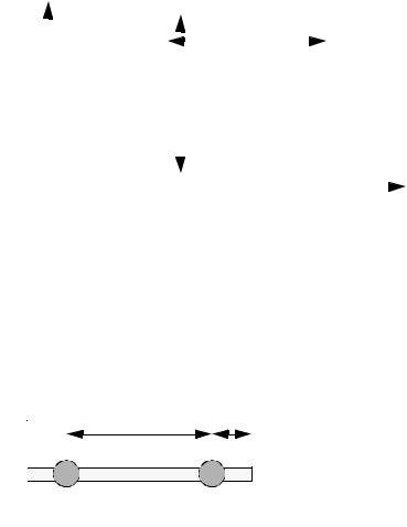
6.Given the scenario below, find the minimum angular resolution of the rotating sensor.
-the robot has +/- 0.5” accuracy
-the pallet can slide +/- 0.1” on the belt

page 294
4.8” |
belt travels |
|
5”
-the driving motor is continuous, and can be run to any angle
-the rotating sensor is an incremental encoder, every rotation of some small angle it issues a pulse. But, because of the construction of the device, it has a minimum resolution for angular measurements
-the robot must be able to touch the part to pick it up
-the tool on the end of the robot is a 1” magnet, and it must be able to touch the part completely to pick it up.
-pulley size is 10” dia.
7.Consider a double jointed manipulator as shown below. It is subjected to a loading at the tip of 8 lbs, and works in a heated environment (i.e. T0(room temp.) = 60°F and T1 (working temp.) =
80°F.
a)Determine the elongation of the manipulator.
b)Determine the total linear deflection of the manipulator.
c)Determine the total final accuracy of the manipulator of the tip of the manipulator.
50” |
10” |
cross section is 1” wide by 2” high solid square aluminum stock
8. For the robot pictured below, assume the that a maximum payload of 10kg is specified. The joints are controlled by stepper motors with 200 steps per revolution. Each of the joints slides, and the gearing is such that 1 revolution of the stepper motor will result in 1” of travel. What is the accuracy of the robot?
page 295
|
|
|
|
|
|
|
|
|
|
|
|
|
Assume the joints are solid, and |
|
|
|
|
|
|
|
|
|
|
|
|
|
|
|
|
|
|
|
|
|
|
|
|
|
|
|
|
|
|
|
|
|
|
|
|
|
|
|
|
|
|
|
|
|
|
|
|
|
|
maximum 10” |
|
||||
|
|
|
|
|
|
|
|
|
|
|
|
|
to robot links are made from 1” |
|
|
|
|
|
|
|
|
|
|
|
|
|
solid aluminum stock. |
|
|
|
|
|
|
|
|
maximum 15” |
|
|
|||
|
|
|
|
|
|
|
|
|
|
|
|
|
|
|
|
|
|
|
|
|
|
|
|
|
|
|
|
|
|
|
|
|
|
|
|
|
|
|
|
|
|
|
|
|
|
|
|
|
|
|
|
|
|
|
|
9. Consider a double jointed manipulator as shown below. It is subjected to a loading at the tip of 8 lbs, and works in a heated environment (i.e. T0(room temp.) = 60°F and T1 (working temp.) = 80°F.
a)Determine the elongation of the manipulator.
b)Determine the total linear deflection of the manipulator.
c)Determine the total final accuracy of the manipulator of the tip of the manipulator.
50” |
10” |
cross section is 1” wide by 2” high solid square aluminum stock