

Piezo systems inc catalog.2005
.pdfDESIGN & PROTOTYPING
PIEZO SYSTEMS, INC.
186 Massachusetts Avenue Cambridge, MA 02139 • Tel: (617) 547-1777 • Fax: (617) 354-2200 • Web: www.piezo.com • E-mail: sales@piezo.com
SOLDER & FLUX KIT
BENDKITINCLUDES:GMOTORS
Solder ■ Tin/Lead solder for nickel electrodes, or Tin/Lead/Silver solder for silver electrodes, 12” length.
Flux ■ Liquid Flux for soldering to nickel or silver electrodes, 7 ml.
■Liquid Flux for soldering to stainless steel & brass center shims , 7 ml.
Wires ■ Red wires, #32 Gauge, Stripped & tinned,
5” length, 5 pieces.
■Black wires, #32 Gauge, Stripped & tinned, 5” length, 5 pieces.
Small piezoceramic
■ Piezoceramic sheet with nickel or silver electrode to practice technique, 1 piece.
PURPOSEBENDINGOFMOTORSTHEKIT
Soldering wires to the electrodes of piezoceramic sheet and/or the center shim of a 2-layer bending element can be difficult if the proper materials are not used. There is a vast array materials to choose from. The solder & flux kit offers the right materials to get started at once and provides information to procure materials directly from the manufacturer later. Recommended procedure is described. Materials in the kit are for soldering to nickel electrodes unless specifically requested for silver.
ORDERING INFORMATION
Solder & Flux Kit (For Nickel Electrodes)
Solder & Flux Kit (For Silver Electrodes)
DESCRIPTION OF ELECTRODES
Piezoceramic electrodes will be either fired silver or nickel. Silver electrodes are flat white in color while nickel electrodes are grey.
Silver electrodes are not recommended for high electric field DC applications where the silver is likely to migrate and bridge the two electrodes. It is often used in nonmagnetic and AC applications. Silver used as an electrode is in the form of flakes suspended in a glass frit. It is generally screened onto the ceramic and fired. The glass makes the bond between the ceramic and the silver particles. Silver is soluble in tin and a silver loaded solder should be used to prevent scavenging of silver in the electrode.
Nickel has good corrosion resistance and is a good choice for both AC and DC applications. It can usually be soldered to easily with tin/lead solder. Electroless nickel, used for plating piezoceramic, contains phosphor. Sometimes the phosphor content in a plating run can make it hard to solder. Vacuum deposited nickel electrodes are usually very thin, making soldering tricky.
Choice of the correct flux (to remove surface oxidation) generally makes soldering to electrode surfaces easy even under adverse conditions.
DESCRIPTION OF CENTER SHIMS
Generally, the center shim layer of a 2-Layer piezoelectric bending element is either brass or stainless steel. A wire is attached to the center shim if the element is used in parallel operation. Shims are soldered in the same way as the nickel electrode. The proper liquid flux choice must be made depending on the shim material.
PART NO. |
1 pc. |
MSF-003-NI |
$49 |
MSF-003-AG |
$59 |
CATALOG #6, 2005 |
51 |
|
|
PIEZOCERAMIC |
||
|
PIEZO SYSTEMS, INC. |
APPLICATION DATA |
|
|
186 Massachusetts Avenue Cambridge, MA 02139 • Tel: |
Web: www.piezo.com • E-mail: sales@piezo.com |
|||
|
||||
(617) 547-1777 • Fax: (617) 354-2200 • |
||||
INTRODUCTION TO PIEZOELECTRICITY
When a piezoceramic element is stressed electrically by a voltage, its dimensions change. When it is stressed mechanically by a force, it generates an electric charge. If the electrodes are not short-circuited, a voltage associated with the charge appears.
A piezoceramic is therefore capable of acting as either a sensing or transmitting element, or both. Since piezoceramic elements are capable of generating very high voltages, they are compatible with today’s generation of solid-state devices — rugged, compact, reliable, and efficient.
The following text describes the terminology of piezoceramics and the relationship among variables for functional applications.
RELATIONSHIPS
Relationships between applied forces and the resultant responses depend upon: the piezoelectric properties of the ceramic; the size and shape of the piece; and the direction of the electrical and mechanical excitation.
To identify directions in a piezoceramic element, three axes are used. These axes, termed 1, 2 and 3, are analogous to X,Y and Z of the classical three dimensional orthogonal set of axes (Figure 1a)
The polar or 3 axis is taken parallel to the direction of polarization within the ceramic. This direction is established during manufacturing by a high DC voltage that is applied between a pair of electroded faces to activate the material. The polarization vector “P” is represented by an arrow pointing from the positive to the negative poling electrode. In shear operations, these poling electrodes are later removed and replaced by electrodes deposited on a second pair of faces. In this event, the 3 axis is not altered, but is then parallel to the electroded
faces found on the finished element (Figure 1b). When the mechanical stress or strain is shear, the subscript 5 is used in the second place.
Piezoelectric coefficients with double subscripts link electrical and mechanical quantities. The first subscript gives the direction of the electrical field associated with the voltage applied, or the charge produced. The second subscript gives the direction of the mechanical stress or strain.
Several piezoceramic material constants may be written with a “superscript” which specifies either a mechanical or electrical boundary condition. The superscripts areT, E, D and S, signifying:
T = constant stress = mechanically free
E = constant field = short circuit
D = constant electrical displacement
=open circuit S = constant strain
=mechanically clamped
As an example, KT3 expresses the relative dielectric constant (K), measured in the polar direction (3) with no mechanical clamping applied.
"D" CONSTANT
The piezoelectric constants relating the mechanical strain produced by an applied electric field are termed the strain constants, or the “d” coefficients. The units may then be expressed as meters per meter, per volts per meter (meters per volt).
strain developed d = applied electric field
It is useful to remember that large dij constants relate to large mechanical displacements which are usually sought in motional transducer devices. Conversely, the coefficient may be viewed as relating the charge collected on the electrodes, to the applied mechanical stress. d33 applies
3
+ |
|
P |
2 |
– |
|
1
Figure - 1a
3
+ |
|
P |
2 |
– |
|
1
Figure - 1b
F
+
+Q or V
P |
– |
– |
|
Figure - 2a
F  –
–
Q or V
+
P  +
+
–
Figure - 2b
+ |
F |
|
|
Q or V |
– + |
– |
P |
|
Figure - 2c
52 |
CATALOG #6, 2005 |

PIEZOCERAMIC APPLICATION DATA
PIEZO SYSTEMS, INC.
186 Massachusetts Avenue Cambridge, MA 02139 • Tel: (617) 547-1777 • Fax: (617) 354-2200 • Web: www.piezo.com • E-mail: sales@piezo.com
when the force is in the 3 direction (along the polarization axis) and is impressed on the same surface on which the charge is collected (Figure 2a). d31 applies when the charge is collected on the same surface as before, but the force is applied at right angles to the polarization axis (Figure 2b).
The subscripts in d15 indicate that the charge is collected on electrodes which are at right angles to the original poling electrodes and that the applied mechanical stress is shear (Figure 2c.)
The |
units for the dij coefficients |
a r e |
c o m m o n l y e x p re s s e d a s |
coulombs/square meter per new- |
|
ton/square meter. |
|
d = |
short circuit charge density |
||
applied mechanical stress |
|
||
|
|||
When the force that is applied is distributed over an area which is fully covered by electrodes (even if that is only a portion of the total electrode) the units of area cancel from the equation and the coefficient may be expressed in terms of change per unit force, coulombs per newton. To view the dij coefficients in this manner is useful when charge generators are contemplated, e.g., accelerometers.
“G” CONSTANT
The piezoelectric constants relating the electric field produced by a mechanical stress are termed the voltage constants, or the “g” coefficients. The units may then be expressed as volts/meter per newton/square meter.
open circuit electric field g = applied mechanical stress
Output voltage is obtained by multiplying the calculated electric field by
the thickness of ceramic between electrodes. A “33” subscript indicates that the electric field and the mechanical stress are both along the polarization axis. (Figure 2a.) A “31” subscript signifies that the pressure is applied at right angles to the polarization axis, but the voltage appears on the same electrodes as in the “33” case. (Figure 2b.)
A “15” subscript implies that the applied stress is shear and that the resulting electric field is perpendicular to the polarization axis. (Figure 2c.)
High gij constants favor large voltage output, and are sought after for sensors.
Although the g coefficient are called voltage coefficients, it is also correct to say the gij is the ratio of strain developed over the applied charge density with units of meters per meter over coulombs per square meter.
strain developed
g = applied charge density
DIELECTRIC CONSTANTS
The relative dielectric constant is the ratio of the permittivity of the material, ε , to the permittivity of free space, ε 0, in the unconstrained condition, i.e., well below the mechanical resonance of the part.
K = |
permittivity of material |
ε |
||
|
= |
|
|
|
permittivity of free space |
ε 0 |
|||
CAPACITANCE
Whereas the relative dielectric constant is strictly a material property, the capacitance is a quantity dependent on the type of material and its dimensions. Capacitance is calculated by multiplying the relative dielectric constant by the permittivity of free space
(ε 0= 8.9 x 10⁻¹² farads/meter) and electrode surface area, and then dividing by the thickness separating the electrodes. Units are expressed in farads.
C |
= |
K ε 0 A |
|
t |
|||
|
|
K3 is related to the capacitance between the original poling electrodes. K1 is related to the capacitance between the second pair of electrodes applied after removal of the poling electrodes for the purposes of shear excitation.
At frequencies far below resonance, piezoelectric ceramic transducers are fundamentally capacitors. Consequently, the voltage coefficients gij are related to the charge coefficients dij by the dielectric constant Ki as, in a capacitor, the voltage V is related to the charge Q by the capacitance C. The equations are:
Q = C V
d33 = KT3 ε 0 g33 d31 = KT3 ε 0 g31 d15 = KT1 ε 0 g15
COUPLING COEFFICIENTS
Electromechanical coupling k33, k31, kp, and k15 describe the conversion of energy by the ceramic element from electrical to mechanical form or vice versa. The ratio of the stored converted energy of one kind (mechanical or electrical) to the input energy of the second kind (electrical or mechanical) is defined as the square of the coupling coefficient.
k = |
mechanical energy stored |
|
electrical energy applied |
||
|
||
|
or |
|
k = |
electrical energy stored |
|
mechanical energy applied |
||
|
CATALOG #6, 2005 |
53 |

PIEZOCERAMIC
P S , I . APPLICATION DATA
IEZO YSTEMS NC
186 Massachusetts Avenue Cambridge, MA 02139 • Tel: (617) 547-1777 • Fax: (617) 354-2200 • Web: www.piezo.com • E-mail: sales@piezo.com
Subscripts denote the relative directions of electrical and mechanical quantities and the kind of motion involved. They can be associated with vibratory modes of certain simple transducer shapes; k33 is appropriate for a long thin bar, electroded on the ends, and polarized along the length, and vibrating in a simple length expansion and contraction. k31 relates to a long thin bar, electroded on a pair of long faces, polarized in thickness, and vibrating in simple length expansion and contraction. kp signifies the coupling of electrical and mechanical energy in a thin round disc, polarized in thickness and vibrating in radial expansion and contraction. k15 describes the energy conversion in a thickness shear vibration. Since these coefficients are energy ratios, they are dimensionless.
to shear strain. Units are usually newtons/square meter.
It should be clearly understood that the piezoceramic properties described above are defined for ideal shapes measured under ideal mechanical and electrical boundary conditions. When put to use under practical device operating conditions, the predicted performance is approached but seldom realized. Non-ideal shapes and non-ideal boundary conditions contribute to transduction losses due to such things as standing waves, interfering vibrational modes, pseudo-clamping, stray electric and dielectric resistances. Since the possibilities are infinite, the designer must evaluate each component under the use conditions for which it is intended.
YOUNG’S MODULUS
As with all solids, piezoelectric ceramics have mechanical stiffness properties described as Young’s Modulus. Young’s Modulus is the ratio of stress (force per unit area) to strain (change in length per unit length).
stress Y = strain
Because mechanical stressing of the ceramic produces an electrical response which opposes the resultant strain, the effective Young’s Modulus with electrodes short circuited is lower than with the electrodes open circuited. In addition, the stiffness is different in the 3 direction from that in the 1 or 2 direction. Therefore, in expressing such quantities both direction and electrical conditions must be specified.YE33 is the ratio of stress to strain in the 3 direction at constant field E (electrodes shorted). YD33 is the equivalent with the electrodes open circuited.YE11 and YD11 are the moduli in the 1 or 2 direction. YE55 andYD55 are the ratios of shear stress
DENSITY
The ratio of the mass to volume in the material, expressed in kg/m3
ρmass
=volume
DISSIPATION FACTOR
A measure of the dielectric losses in the material-defined as the tangent of the loss angle or the ratio of parallel resistance to the parallel reactance, expressed in percent.
MECHANICAL (QM)
The ratio of reactance to resistance in the equivalent series circuit representing the mechanical vibrating resonant system. The shape of the part affects the value.
CURIE TEMPERATURE
The temperature at which the crystal structure changes from a non-sym- metrical (piezoelectric) to a symmetrical (non-piezoelectric) form, expressed in degrees Celsius.
AGING RATE
Aging is the attempt of the ceramic to change back to its original state prior to polarization. Aging of piezoelectric ceramics is a logarithmic function with time. The aging rate defines change in the material parameters per decade of time, i.e., 1-10 days, 5-50 days, etc.
PYROELECTRICITY
Piezoelectric materials are also pyroelectric. They produce electric charge as they undergo a temperature change. When their temperature is increased, a voltage develops having the same orientation as the polarization voltage. When their temperature is decreased, a voltage develops having an orientation opposite to the polarization voltage, creating a depolarizing field with the potential to degrade the state of polarization of the part.
The maximum electric field which arises due to a temperature shift is:
E(pyro) = α ( ∆εT)
K3 0
where E(pyro) is the induced electric field in volts/meter, α is the pyroelectric coefficient in Coulomb/°C meter2, ∆ T is the temperature difference in °C, K3 is the dielectric constant, and ε 0 is the dielectric permittivity of free space. For PZT piezoceramic, α is typically ~ 400x10-6 coulomb/°C meter2.
CRYOGENIC
The piezoelectric strain coefficient decreases significantly at cryogenic temperatures, but does not vanish. At 77°K and 4.2°K the strain coefficient decreases to about 33% and 14% respectively, of its room temperature value. However, the coercive field increases, allowing the piezo to be driven harder.
54 |
CATALOG #6, 2005 |

PIEZOCERAMIC APPLICATION DATA
PIEZO SYSTEMS, INC.
186 Massachusetts Avenue Cambridge, MA 02139 • Tel: (617) 547-1777 • Fax: (617) 354-2200 • Web: www.piezo.com • E-mail: sales@piezo.com
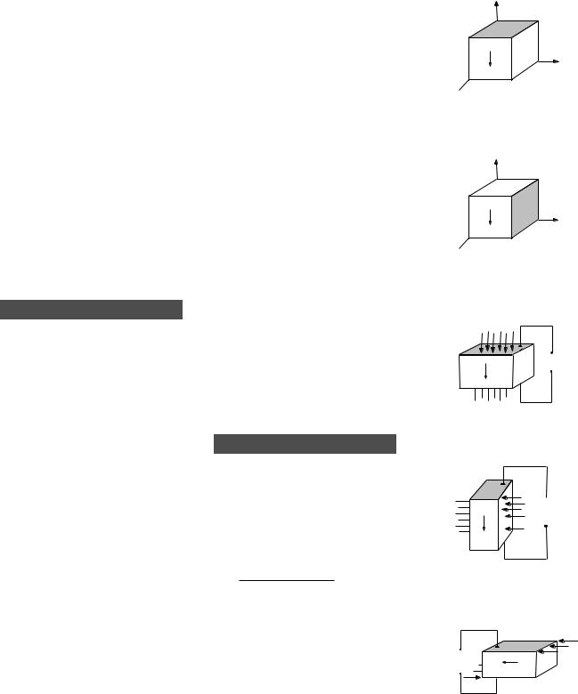
MOTOR TRANSDUCER RELATIONSHIPS
PARALLEL EXPANSION & CONTRACTION MOTOR
– |
|
|
|
V |
|
+ |
+ |
P |
|
– |
|
|
L+ ∆ L |
|
|
|
T-∆ T
∆ T
∆ T
+ |
P |
|
T |
– |
|
||
|
L |
W |
|
|
|
||
|
|
|
+ |
|
P |
T |
|
∆ |
||
|
|
||
– |
|
|
T+ |
|
|
L– ∆ L
+ |
Parallel Expansion |
V |
∆ T = Vd33 |
– |
TRANSVERSE EXPANSION & CONTRACTION MOTOR
–
V
+ |
|
+ |
|
P |
|
|
|
||||
|
|
– |
|
||
|
|
|
|
L+ ∆ L |
|
|
|
|
|
|
|
|
|
|
|
|
|
|
|
|
|
|
|
T-∆ T
∆ T
∆ T
+ |
P |
|
T |
– |
|
||
|
L |
W |
|
|
|
||
|
|
|
+ |
|
P |
T |
|
∆ |
||
|
|
||
– |
|
|
T+ |
|
|
L– ∆ L
 + Transverse Expansion
V |
∆ L |
|
|
∆ W |
|
|
Vd31 |
||
– |
= |
|
= |
|
|||||
|
L |
|
|
W |
|
T |
|
||
PARALLEL SHEAR MOTOR
|
|
|
∆ x |
|
|
|
– |
|
|
|
|
V |
+ |
V |
– + |
– + |
– |
+ |
X = Vd15 |
|
+ |
P |
P |
P |
|
|
– |
|
|
|
|
|
∆ x
BENDING MOTOR
|
|
+ |
|
|
|
|
|
|
V |
|
|
T |
|
+ |
P |
– |
|
P |
P |
|
+ |
+ |
|||||
– |
|
|
– |
|
– |
|
– |
P |
∆ X |
– |
P |
– |
P |
+ |
|
+ |
+ |
|
L
+– P |
– |
|
+– P |
P |
+– P |
T |
+– P |
+– P |
|
|
V |
|
L |
|
|
+ |
|
|
|
|
|
|
|
Series Connection
∆ X
|
|
|
|
|
V – |
X |
= |
2L2 V d31 |
|
|
|
|
|
|
|
|
T2 |
||||||
|
|
|
|
|
|||||||
|
|
|
|
|
|
+ |
|
|
|||
|
|
|
|
|
|
|
|
|
|
|
|
|
|
|
|
|
|
|
|
|
|
|
|
|
|
|
|
|
– |
Parallel Connection |
|||||
|
|
|
|
|
|||||||
|
|
|
|
||||||||
|
|
V |
|||||||||
|
|
|
+ |
|
X |
= |
4L2 V d31 |
|
|||
|
|
|
|
||||||||
|
|
|
|
|
|
|
|
||||
|
|
|
|
|
|
|
|||||
|
|
|
|
|
|
|
T2 |
||||
|
|
|
|
|
|
|
|
|
|||
CATALOG #6, 2005 |
55 |

|
|
PIEZOCERAMIC |
||
|
PIEZO SYSTEMS, INC. |
APPLICATION DATA |
|
|
186 Massachusetts Avenue Cambridge, MA 02139 • Tel: |
Web: www.piezo.com • E-mail: sales@piezo.com |
|||
|
||||
(617) 547-1777 • Fax: (617) 354-2200 • |
||||
GENERATOR TRANSDUCER RELATIONSHIPS
PARALLEL COMPRESSION OR TENSION GENERATOR
F
+ 
+
Q or V – P
– 
+ |
|
P |
|
|
|
||
– |
|
|
|
|
|
||
|
|
L |
|
T
W
F |
|
|
|
|
|
|
|
Q |
= |
Fd33 |
|
+ |
– |
|
|
|
|
Q or V |
|
|
Fg33 |
||
– P |
V |
= |
|||
+ |
|||||
|
|
T |
|
LW |
TRANSVERSE COMPRESSION OR TENSION GENERATOR
– |
+ |
F |
+ |
|
|
|
+ |
|
F + |
|
Q or V |
P |
P |
T |
|
P |
Q or V |
||||
– |
– |
W |
– |
|||||||
+ |
– |
|||||||||
|
|
|
|
L |
|
|
|
PARALLEL SHEAR GENERATOR
+ |
|
|
F |
|
|
|
|
|
|
– |
– |
+ |
– |
+ |
|
|
– |
|
+ |
||
Q or V |
T |
|
|
Q or V |
||||||
|
P |
P |
L |
W |
F |
P |
|
|||
– |
|
|
|
+ |
||||||
|
|
|
|
|
|
|
|
|
Q |
|
= |
|
F d31 |
||
|
LW |
|
|
TW |
|||
|
|
|
|
||||
|
V |
|
= |
F g31 |
|
||
|
T |
TW |
|||||
|
|
|
|||||
Q |
= Fd15 |
||
V |
= |
F g15 |
|
T |
LW |
||
|
|||
TRANSVERSE SHEAR GENERATOR
F
+ 
Q or V |
– |
+ |
|
|
P |
|
|
– |
|
||
|
|
|
|
–+
P L
T
W
|
|
Q |
= |
F d15 |
– + |
– |
LW |
|
TW |
Q or V |
|
|
|
|
P |
|
|
F g15 |
|
+ |
V |
|
||
|
= |
|||
|
|
T |
TW |
|
|
|
|
F
BENDING GENERATOR
|
|
F |
|
|
Series |
|
|
F |
|
|
|
|
Connection |
|
|
||||
|
W |
|
+ |
|
|
|
|||
|
|
|
|
|
3FL2 d31 |
|
|
|
|
|
+– |
P |
Q or V |
Q |
= |
+– |
P |
+ |
|
T |
– |
P |
– |
2T2 |
+– |
|
|||
+ |
|
|
P |
||||||
|
L |
|
|
|
|
|
|
|
Q or V |
|
|
|
|
|
3FL g31 |
|
|
– |
|
|
|
|
|
V |
= |
|
|
||
|
|
|
|
2WT |
|
|
|
||
|
|
|
|
|
|
|
|
|
|
Parallel
Connection
Q |
= |
3FL2 d31 |
|
|
|
T2 |
|
V |
= |
3FL g31 |
|
4WT |
|||
|
|
56 |
CATALOG #6, 2005 |
PIEZOCERAMIC APPLICATION DATA