

Piezo systems inc catalog.2005
.pdfPIEZO SYSTEMS, INC.
186 Massachusetts Avenue Cambridge, MA 02139 • Tel: (617) 547-1777 • Fax: (617) 354-2200 • Web: www.piezo.com • E-mail: sales@piezo.com
TABLE OF CONTENTS - CATALOG #6
ENGINEERING
OEM COMPONENT DEVELOPMENT |
2 |
||
PRODUCTS |
|
|
|
ELECTRONICS |
|
|
|
Piezo Linear Amplifier |
|
4 |
|
Small Low-cost Linear Amplifier |
6 |
||
Proportional Voltage Booster |
8 |
||
DC to AC Inverter Drive Circuit |
9 |
||
MOTION INSTRUMENTS |
|
|
|
1 - Axis |
Mirror Tilters, |
± 0.35°, ±.55°, ± 0.75°, ±.95° |
10 |
2 - Axis |
Mirror Tilter, |
± 1.6° |
12 |
FANS AND RESONATORS |
|
|
|
Piezoelectric Fans |
|
|
|
|
■ 115VAC/60Hz Version |
14 |
|
|
■ Low Voltage DC Version |
15 |
|
Piezoelectric Chopper |
|
16 |
|
DESIGN AND PROTOTYPING |
|
|
|
Piezoelectric Motor/Actuator Kit |
17 |
||
Piezoelectric Generator/Sensor Kit |
18 |
||
TRANSDUCERS (MOTOR / ACTUATORS AND GENERATOR / SENSORS) |
|
||
Introduction to Piezo Transducers |
19 |
||
1-Layer Piezo Transducers (Single Sheets) |
|
||
|
■ 5A Type Piezoceramic ■ 5H Type Piezoceramic |
23 |
|
2-Layer Piezo Benders & Extenders |
|
||
Basic Transducers, Benders & Extenders |
26 |
||
|
■ Standard Brass Reinforced (Actuators & Sensors) |
28 |
|
|
■ High Performance |
33 |
|
|
■ Non-Magnetic |
35 |
|
|
■ High Strength Stainless Steel Reinforced |
36 |
|
Pre-mounted & Wired, Benders & Extenders |
|
||
|
■ Quick-Mounts |
37 |
|
|
■ Double-Quick-Mounts |
42 |
|
Circular Bending Disks |
47 |
||
4-Layer Piezo Benders |
|
48 |
|
Multi-Layer Low Voltage Piezo Stacks |
49 |
||
Solder / Flux Kit |
|
51 |
|
PIEZOCERAMIC APPLICATION DATA |
|
||
Introduction to Piezoelectricity |
52 |
||
Motor Transducer Relationships |
55 |
||
Generator Transducer Relationships |
56 |
||
Typical Thermal Properties of Piezoceramic |
57 |
||
SERVICE ANDWARRANTY: All Piezo Systems, Inc. products are warranted against defective materials and workmanship. This warranty applies for a period of time of one year from the date of delivery to the original purchaser. Any instrument or part that is found within the one year period not to meet these standards, will be repaired or replaced. No other warranty is expressed or implied. NOTE: Prices and specifications subject to change without notice.
1 |
CATALOG #6, 2005 |
ENGINEERING
PIEZO SYSTEMS, INC.
186 Massachusetts Avenue Cambridge, MA 02139 • Tel: (617) 547-1777 • Fax: (617) 354-2200 • Web: www.piezo.com • E-mail: sales@piezo.com
OEM COMPONENT DEVELOPMENT
|
|
|
CUSTOMER SPECIFICATIONS |
|
|
|
Piezoceramic actuator design is based on customer spec- |
||
|
|
ifications which include as a minimum: |
||
|
|
■ |
Motion and force requirements |
|
|
|
■ |
Space available |
|
|
|
■ Voltage available |
||
|
|
■ Thermal operating range |
||
|
|
■ |
Frequency operating range or response time |
|
|
|
Dynamic sensor design is based on customer specifica- |
||
|
|
tions which include as a minimum: |
||
|
|
■ Voltage and current requirements |
||
|
|
■ |
Space available |
|
|
|
■ |
Force or strain available |
|
|
|
■ Thermal operating range |
||
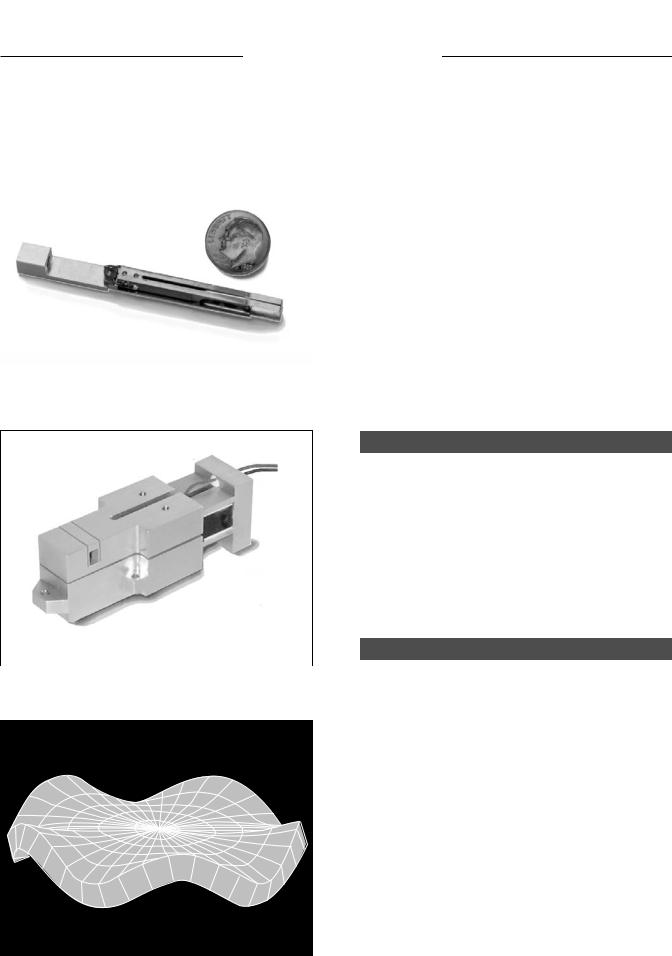
HIGH FREQUENCY TUNING FORK |
||||
|
■ |
Frequency range or transient response time |
||
|
|
|||
HIGH OUTPUT ACTUATOR
FEA MODELING
CATALOG #6, 2005
ACTUATOR & SYSTEM DESIGN
Using extensive computer software and experience, Piezo Systems can move quickly from your specifications to a complete optimized design and prototype. The geometry, electroactive material, internal lamination, polarization, electrode configuration, mount, power take-off, and production process is designed to ensure repeatable and reliable performance.
Piezo Systems can also design and build the electronic system to drive or monitor the transducer, and fabricate (or mold) the structure to which the piezo is mounted.
OEM PRODUCT DEVELOPMENT
Piezo Systems Inc. offers engineering services for custom OEM component development. Our experience allows the elimination of potential design flaws which plague those unfamiliar with piezoceramic technology, especially in the areas of lamination bonding, flexure design, ceramic stress and fatigue criteria, thermal stability, mounting, power take-off attachments, electronic drive, testing, and evaluation. This service reduces the customer’s need to dedicate highly qualified personnel during the development period, and development time is typically reduced from years to months. Financial and technical risks are minimized. The following phases are quoted on a fixed price basis:
■Analysis and Design Phase: Communication of specifications, analysis, and optimized design of transducer.
■Prototype Phase: Samples built to specification.
■Pre-production Phase: Pre-production samples for exhaustive testing.
■Production Phase: Production pieces at desired volume.
2
ENGINEERING
AREAS OF EXPERTISE
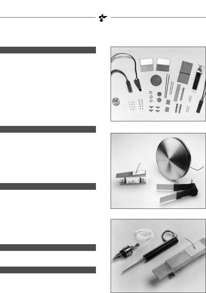
BENDING ACTUATORS & SENSORS
Piezo Systems specializes in manufacturing bending elements. A proprietary bonding process and ceramic qualifying program leads to consistent performance, highstrength, thermally stable, void free, multilayer laminations. Advanced cutting techniques produce actuators with dimensional tolerances within ±.001 inch if necessary; chip free edges; non-linear shapes; and contamination free surfaces. Piezo Systems ships parts to performance specifications, not merely to dimensional tolerance. Our bending actuators are employed in piezo valves, choppers, modulators, fans, tunneling microscopes, and soil testers. Our bending sensors are used in implantable pacemakers and industrial equipment.
RESONANT DEVICES
BENDING ELEMENTS
Resonant devices are an effective way of achieving high periodic motion at low voltage and power. Products designed to operate at a single frequency require special attention be paid to dimensional uniformity, material consistency, and process control. A careful balance is sought between minimizing strain on the piezoceramic and maximizing the dynamic amplitude. Energy losses due to internal dissipation, external attachments, and output loading are addressed.
ULTRASORESONANTICDEVICES
Ultrasonics, a special portion of the resonant spectrum, find extensive use over a wide range of application areas. These devices are designed according to the same principles guiding resonant devices. However, additional consideration is given to amplitude stability, power consumption, over-heating, resonance tracking, and electronic drive.
Piezo Systems has developed a monolithic construction which eliminates many of the problems associated with precompressed bolt together systems.
CONSULTING & ANALYSIS
Piezo Systems offers consultation on an hourly, daily, weekly, and monthly basis.
PRODUCTION
Combined with proprietary processing techniques, Piezo Systems works closely with a network of highly specialized vendors. As a result Piezo Systems is capable of supplying highly sophisticated single parts or hundreds of thousands of parts per year.
RESONATORS
ULTRASONICS
3 |
CATALOG #6, 2005 |

ELECTRONICS
PIEZO SYSTEMS, INC.
186 Massachusetts Avenue Cambridge, MA 02139 • Tel: (617) 547-1777 • Fax: (617) 354-2200 • Web: www.piezo.com • E-mail: sales@piezo.com
PIEZO LINEAR AMPLIFIER
LOW EL E C T R I C A L NO I S E - NO FA N
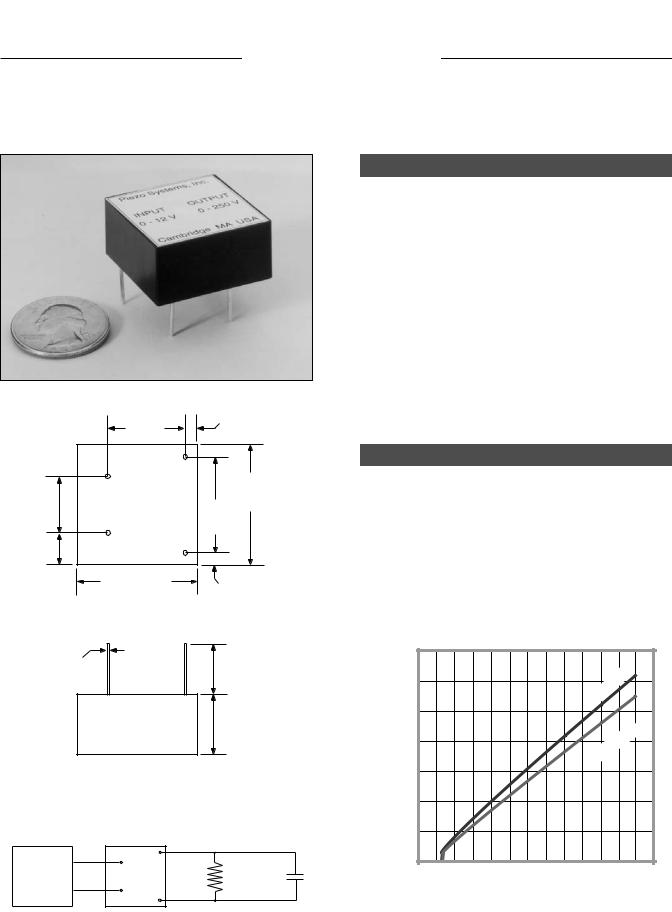
DESCRIPTION
5
(127)
PIEZO SYSTEMS, INC. |
PIEZO AMPLIFIER MODEL EPA-104 |
CAMBRIDGE, MA |
|
DC OFFSET |
|
VOLTAGE |
|
|
OUTPUT |
|
± 200 VOLT |
|
200 mA |
|
INPUT |
|
± 10 Vp MAX |
GAIN |
|
DC POLARITY |
CAUTION |
HIGH VOLTAGE
12 (305)
Piezo Systems offers a general purpose, single channel, high voltage (± 200 Vp), high current (± 200 mA), and high frequency (DC to 300 KHz) amplifier designed to drive any load including piezo stacks, benders, and single sheets.
Low Electrical Noise, Low Distortion: The EPA-104 is made with a high quality Apex® High Voltage Hybrid Operational Amplifier, and utilizes low noise linear power supplies. It is housed in a heavy high conductivity aluminum case which provides an excellent shield from external electromagnetic interference.
Input and Output Protection: Piezo loads present special problems to electronic drivers. The EPA-104 provides heavy input and output protection to take care of all shorting, turnon, turn-off, and load generated voltage occurrences which can damage either the amp or your actuator.
Manual Bias Controls (Polarity and DC offset): For making manual adjustments of drive voltage or for applying DC bias to dynamically driven piezo actuators such as piezo stacks.
Input (via analog signal to the BNC input connector): Accepts up to ± 10 Vp signal waveforms from external signal generators, computer controllers, or feedback networks from DC to rated frequency. The combined AC plus DC offset voltage is adjustable from zero to the maximum rated voltage.
SAMPLE SCOPE OUTPUTS
Load: 0.1 µF Capacitor @ 1KHz
Channel 1: Input
Scale = 0.5 Vp / div 1 Time Base =250 µsec/ div
Channel 2: Output
Scale = 5 Vp / div
Time Base =250 µsec/ div
2
Load: 0.1 µF Capacitor @ 1KHz
Channel 1: Input
Scale = 5.0 Vp / div
Time Base =250 µsec/ div Channel 2: Output
Scale = 50 Vp / div 1 Time Base =250 µsec/ div
2
ORDERING INFORMATION
Piezo Linear Amplifier, |
± 200 Vp/200mA |
(115VAC, 60Hz) |
Piezo Linear Amplifier, |
± 200 Vp/200mA |
(230VAC, 50Hz) |
Insulated Banana Plugs, |
Red & Black |
|
Gain Control: Convenient front panel adjustment of amplifier gain from 0 to 20X.
Output (via 4mm diameter safety sockets): High-voltage output terminals meet IEC1010 safety standard. Red and black insulated banana plugs with retractable sheath may be purchased separately. Wire connection to plugs is made with recessed screw.
NOTE ON PIEZO LOADS
To estimate the peak current requirement of a piezo actuator, solve the following equation:
Ip = 2 π F C Vp (in Amperes)
where F is the maximum operating frequency in Hertz, C is the capacitance of the piezo device in Farads, andVp is maximum peak voltage required by the piezo actuator. The amplifier must be able to supply both Vp and Ip.
PART NO. |
PRICE |
EPA-104-115 |
$2,399 |
EPA-104-230 |
$2,399 |
EPA-104-BPRB |
$49 |
CATALOG #6, 2005 |
4 |
ELECTRONICS
SPECIFICATIONS
EPA-104 PIEZO LINEAR AMPLIFIER
ELECTRICAL |
|
|
Maximum Voltage |
±200 volts peak |
|
Maximum Current |
±200 mA peak |
|
Output Power |
40.0 watts peak |
|
Frequency Range |
DC to 300 KHz |
|
Full Power Bandwidth |
|
|
(Into 1 KΩ resistive load) |
Flat (to within ±0.5 dB): DC to 250 KHz |
|
|
3db roll-off: 400 KHz |
|
(Into capacitive load) |
See chart below |
|
Voltage Gain |
Variable gain, adjustable from 0 to 20X |
|
Phase Shift |
-.083° per KHz, typical |
|
Slew Rate (No Load) |
380 volts / µsec |
|
Maximum Input Voltage |
±10 volts peak |
|
Maximum DC Component |
±10 volts DC |
|
Input Coupling |
Direct DC coupling only |
|
Input Impedance |
10K ohm |
|
Output Coupling |
DC coupling |
|
Variable DC Offset |
Normally zero volts. Adjustable to ±200 volts peak |
|
Load Impedance |
Capable of driving any load within the voltage and |
|
|
current limitations of the amplifier. |
|
Output Noise (300KHz bandwidth) |
2 mvrms typical with input shorted |
|
AC Power Source |
User settable (fuse change required): 100 - 130 VAC, 50/60 Hz |
|
|
|
200 - 250 VAC, 50/60 Hz |
Circuit Protection |
Overload, short circuit, and thermal protection |
|
MECHANICAL |
|
|
Front Panel Controls |
Gain adjust; DC Polarity selector (+,0,-); DC Offset adjust |
|
Rear Panel Controls |
On/off switch; Line voltage selector |
|
Terminals |
BNC for input (ground referenced); Safety shrouded banana jacks |
|
|
for high voltage output terminals (ground referenced) |
|
Weight |
6.4 kg |
(14 lbs.) |
Dimensions |
305mm L x 305mm D x 127mm H (12” L x 12” D x 5” H) |
|
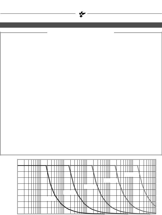
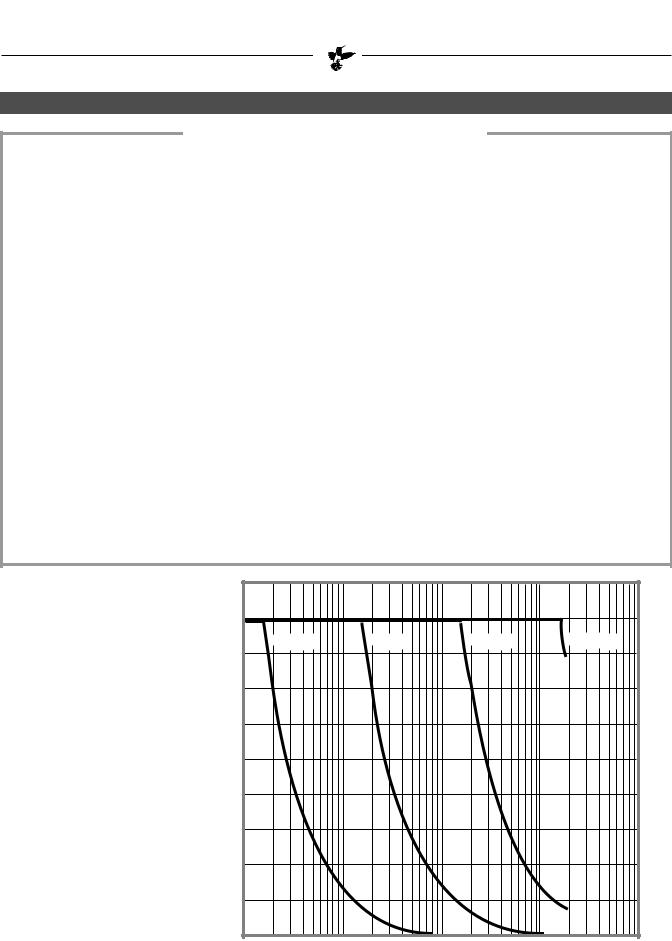
Volts Peak
200
175
C = .001 F
150
C = .01 F
125
C = .1 F
100
C = 1 F
75
C = 10 F
50
25
0
100 |
101 |
102 |
103 |
104 |
105 |
106 |
|
|
|
Frequency (Hertz) |
|
|
|
Peak Voltage Delivered to Capacitive Load at Peak Current Rating as a Function of Operating Frequency (Steady State Sinusoidal Waveforms; Temperature = 25 °C)
5 |
CATALOG #6, 2005 |
ELECTRONICS
PIEZO SYSTEMS, INC.
186 Massachusetts Avenue Cambridge, MA 02139 • Tel: (617) 547-1777 • Fax: (617) 354-2200 • Web: www.piezo.com • E-mail: sales@piezo.com
LOW COST - PIEZO LINEAR AMPLIFIER
±180VP / ±30M A
DESCRIPTION
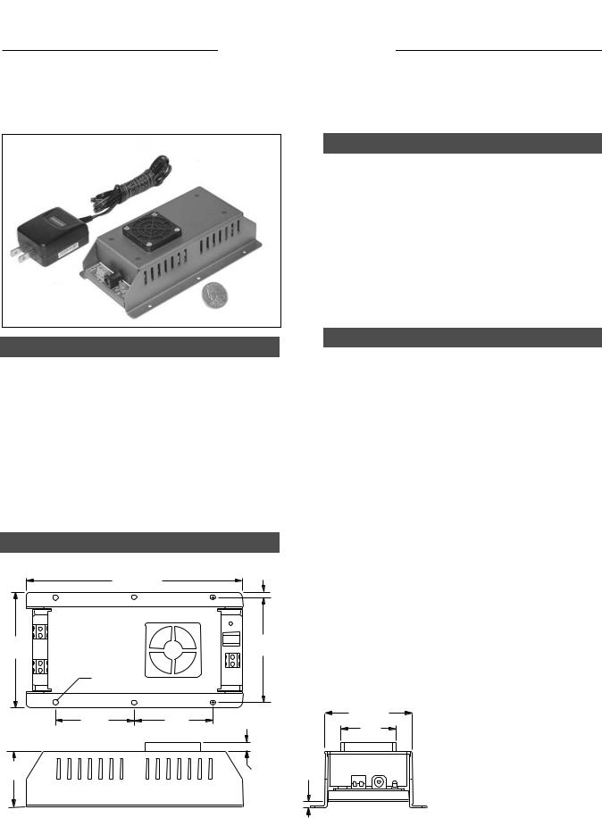
The EPA-007-012 is a compact, high voltage, non-invert- ing, linear amplifier with an integral high voltage power supply. It is designed to be small in size and convenient for both bench top experimentation and OEM installation. It requires only a single 15 VDC power input (provided), yet will accept +/- 10 V ground referenced input and produce +/- 180 V ground referenced output.
It is designed to be used as a high voltage drive source for various piezoelectric actuating devices and servo applications in the DC to 1500 Hz frequency range.
NOTE ON PIEZO LOADS
To estimate the peak current (Ip) requirement of a piezo actuator, solve the appropriate equation:
Sine wave |
Ip |
= |
2 π f C Vp |
Triangle wave |
Ip |
= |
4 f C Vp |
Square wave |
Ip |
= |
C dV / dt |
Where Ip is the peak current in Amperes, f is the maximum operating frequency in Hertz, C is the capacitance of the piezo device in Farads, dt is the square wave rise time, and Vp is maximum peak drive voltage.The amplifier must be able to supply Vp, lp and f simultaneously.
DIMENSIONS
0.150
(3.81)
6.18 (157)
3.30 |
3.00 |
(83.8) |
(76.2) |
FEATURES
Input Power: For bench top experimentation, where minimum setup time and flexibility of amplifier location are real advantages, an AC adapter (115VAC/60Hz to 15VDC) is provided. For OEM or permanent installation, an auxillary DC input is provided consisting
of a set of screw terminals.
Signal Input: Input to the amplifier is made by connecting wires to the screw terminal connector on the I/O panel at one end of the unit.This is a ground referenced ±10 Vpeak low voltage input.
High Voltage Output: Output from the amplifier appears at the two screw terminals on the I/O panel.
Loads: The EPA 007-012 is designed for driving piezo actuator loads.
Input and Output Protection: Piezo loads present special problems to electronic drivers.The EPA-007-012 provides input and output protection to take care of all shorting, turn-on, turn-off, and load generated voltage occurrences which can damage either the amp or your actuator.
Clearance hole for #6-32 screw. 6 places.
2.250 |
2.250 |
2.50 |
(63.5) |
|
1.575 |
||||
(57.15) |
(57.15) |
|||
|
|
(40.0) |
||
1.60 |
0.25 |
0.166 |
|
|
(40.6) |
(6.35) |
(4.22) |
|
|
ORDERING INFORMATION |
PART NO. |
1 pc. |
5 pc. |
25 pc. |
100 pc. |
Low Cost Piezo Linear Amplifier |
EPA-007-012 |
$899 |
$839 |
$749 |
$699 |
CATALOG #6, 2005 |
6 |
ELECTRONICS
SPECIFICATIONS
EPA-007-012 PIEZO LINEAR AMPLIFIER
ELECTRICAL
Amplifier Polarity |
Non-inverting type, output in phase with input |
Maximum Output Voltage |
±180 volts peak |
Maximum Output Current |
±30 mA peak continuous |
Output Power |
5.4 watts peak |
Open Circuit Frequency Response |
Flat within ± 15% from 0 to 1,500 Hz |
Voltage Gain |
Fixed gain, 20X, ±5% |
Maximum Input Voltage |
±10 volts peak |
Maximum DC Component |
±10 volts DC |
Input Coupling |
DC coupled |
Input Impedance |
10K ohm |
Output Coupling |
DC coupled |
Output Ripple |
70 mV rms, with input shorted |
Permissible Loads |
Piezo, capacitive, resistive (not recommended for purely inductive |
|
loads) |
Power Source |
+13 VDC to + 18VDC, 750 mA |
Current Draw |
400 mA no load; 700 mA full load |
Circuit Protection |
Simple circuit limit, ~30 mA |
Short Circuit Endurance |
Indefinite |
Cooling |
Internal brushless DC fan |
Isolation |
Ground terminals for signal input, High voltage output, and 15 VDC |
|
power input are electrically common. |
MECHANICAL |
|
|
|
|
|
|
Weight |
256 g |
(9 oz.) |
|
|
|
|
Dimensions |
157mm L x 84mm D x 46mm H |
|
|
|||
|
(6.18” L x 3.3” W |
x |
1.825” H) |
|
|
|
|
200 |
|
|
|
|
|
Peak Output Voltage |
|
|
|
|
|
|
versus |
180 |
|
|
|
|
|
Frequency |
C=10 F |
C=1 F |
|
C=.1 F |
|
C=.01 F |
for Various |
|
|
||||
Capacitive Loads |
160 |
|
|
|
|
|
Sinusoidal Waveforms |
140 |
|
|
|
|
|
@ = 25 °C |
|
|
|
|
|
|
|
120 |
|
|
|
|
|
Volts |
100 |
|
|
|
|
|
(peak) |
|
|
|
|
|
|
|
|
|
|
|
|
|
|
80 |
|
|
|
|
|
|
60 |
|
|
|
|
|
|
40 |
|
|
|
|
|
|
20 |
|
|
|
|
|
|
0 |
|
|
|
|
|
|
1 |
10 |
|
100 |
1,000 |
10,000 |
Frequency (Hz)
7 |
CATALOG #6, 2005 |
ELECTRONICS
PIEZO SYSTEMS, INC.
186 Massachusetts Avenue Cambridge, MA 02139 • Tel: (617) 547-1777 • Fax: (617) 354-2200 • Web: www.piezo.com • E-mail: sales@piezo.com
PROPORTIONAL VOLTAGE BOOSTER
|
|
|
|
.125 |
|
|
.80 |
|
(3.2) |
|
|
|
|
|
|
|
(20.3) |
|
|
|
|
|
_ |
|
|
+ |
|
|
1.25 |
|
|
|
|
|
.60 |
IN |
|
OUT |
(31.8) |
(15.2) |
|
1.00 |
||
|
|
|
||
|
_ |
|
|
(25.4) |
|
|
|
|
|
.325 |
|
|
+ |
|
(8.3) |
|
|
|
|
|
1.25 |
(31.7) |
|
.125 |
|
|
|
|
(3.2) |
|
Bottom View |
|
||
.04 |
(1.0) |
|
|
.55 |
|
|
(14.0) |
||
Dia. Typical |
|
|
Typical |
|
|
|
|
|
.63 |
|
|
|
|
(1.6) |
|
|
|
|
Max |
A 500 KΩ discharge resistor across the output terminals is recommended to sink charge when input voltage is removed.
0 - 12 V |
+ |
_ |
|
|
|
IN |
OUT |
RD |
CPIEZO |
||
Input |
|||||
Voltage |
_ |
+ |
|
|
DESCRIPTION
The Proportional Voltage Booster provides a simple means of obtaining the high DC voltage used for driving piezo devices statically. It requires only a low voltage DC supply (or the output of an op-amp) on the input leg and a drain resistor on the output leg.
The Voltage Booster is small, PCB mountable, and well suited for low current / high voltage applications. Output voltage is proportional to input voltage, and is linear from ~ 10% to the maximum output voltage. Features include: low output ripple; floating output to enable the user to choose either positive or negative drive; short circuit protection; and, reverse polarity protection.
BOOSTER SPECIFICATIONS
Input Voltage: |
0 - 12 VDC |
Input Current: |
85 mA Nominal |
Output Voltage: |
0 - 250 VDC Nominal |
Output Current: |
2 mA |
Load Regulation: |
5% (1/2 to full load) |
Ripple: |
< 0.5% p-p |
Insulation Resistance: |
3500 VDC |
Weight: |
42 grams |
Temperature Range: |
-20°C to +70°C |
|
300 |
|
|
|
|
|
|
|
|
|
|
Load |
|
|
|
|
|
|
|
|
|
|
|
|
|
|
|
(VDC) |
250 |
|
|
|
|
|
|
|
|
|
No |
|
|
|
|
|
|
|
|
|
|
|
|
|
|
||
Voltage |
|
|
|
|
|
|
|
|
|
|
|
|
|
200 |
|
|
|
|
|
|
|
|
|
Ω |
|
|
|
|
|
|
|
|
|
|
|
|
R=500 |
K |
|
|
|
Output |
150 |
|
|
|
|
|
|
|
|
|
|
||
100 |
|
|
|
|
|
|
|
|
|
|
|
|
|
|
|
|
|
|
|
|
|
|
|
|
|
|
|
|
50 |
|
|
|
|
|
|
|
|
|
|
|
|
|
0 |
|
|
|
|
|
|
|
|
|
|
|
|
|
0 |
1 |
2 |
3 |
4 |
5 |
6 |
7 |
8 |
9 |
10 11 |
12 |
|
|
|
|
|
|
Input Voltage |
(VDC) |
|
|
|||||
ORDERING INFORMATION |
PART NO. |
1 pc. |
5 pc. |
25 pc. |
100 pc. |
Proportional Voltage Booster |
EVB-304 |
$349 |
$299 |
$249 |
$199 |
CATALOG #6, 2005 |
8 |
PIEZO SYSTEMS, INC.
ELECTRONICS
186 Massachusetts Avenue Cambridge, MA 02139 • Tel: (617) 547-1777 • Fax: (617) 354-2200 • Web: www.piezo.com • E-mail: sales@piezo.com
DC TO AC INVERTER DRIVE CIRCUIT
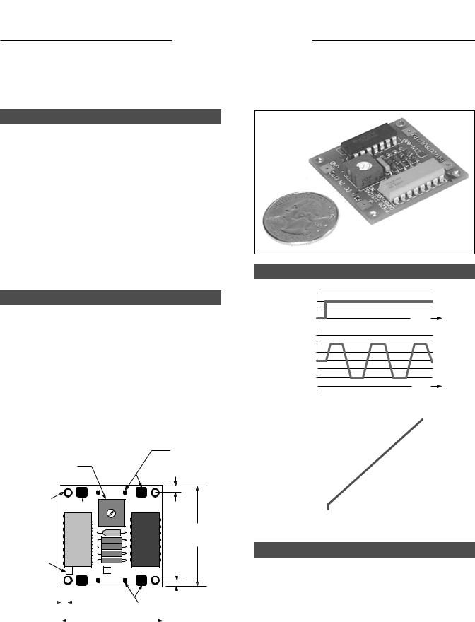
DESCRIPTION
The Inverter Drive Circuits convert DC input voltage (from 0 to +44VDC) to AC output voltage (from 0 to ±44 Vpeak) for driving low frequency (50 Hz - 450 Hz) piezo devices such as fans, choppers, vibrators, and benders at resonance.
Output frequency is manually adjusted by turning the trimmer pot on the PCB. Optimum tuning is accomplished by observing device amplitude or the output waveform on an oscilloscope during operation. Large input and output terminal pads are provided for clip leads during bench-top testing, and small pads are provided for permanent wiring. #2-56 clearance holes are provided for mounting the board on stand-offs.
DRIVING PIEZO RESONATORS
Resonant Piezo Chopper: The 100 Hz piezo chopper (see page 16) may be driven using the EIN-407.
Piezo Benders: Bending elements (see pages 26-47) may be driven at resonance to achieve high deflection at low power. Depending on tip load, use the appropriate inverter circuit.
Piezo Fans: Piezo fans are driven at resonance. Depending on the design, resonant frequency is typically between
60 - 250 Hz. Use the appropriate inverter circuit (see pages 14-15).
Trimpot for |
INPUT pads |
for wires or |
|
frequency adjustment |
clip leads. |
#2-56 clearance holes for mounting,
4 plcs.
Part Number
Box
P1 |
DC IN |
P2 |
|
PIEZO SYSTEMS |
|
FREQ |
GND |
|
.093" |
||
CAMBRIDGE, MA |
|
||
|
|
|
(2.4) |
|
|
|
1.50" |
|
|
|
(38.1) |
|
|
|
.093" |
EIN - 407 |
EIN - 408 |
(2.4) |
|
|
|||
P4 |
OUTPUT |
P3 |
|
.125" (3.2) |
|
|
|
|
|
|
|
|
|
|
|
|
|
|
|
|
|
|
|
|
|
|
|
|
|
|
|
|
|
|
|
|
|
|
|
|
|
|
|
|
|
OUTPUT pads |
||
|
|
|
|
|
|
|
|
|
|
|
|
|
for wires or |
|
|
|
|
|
|
|
|
|
1.50" (38.1) |
|
|
|
|
clip leads. |
|
|
|
|
|
|
|
|||||||||
INPUT / OUTPUT WAVEFORM
Input |
+ |
|
|
|
|
Voltage |
|
|
(VDC) |
0 |
Time |
|
|
+ |
|
Output |
0 |
|
Voltage |
|
|
(±Vpeak) |
|
|
|
- |
Time |
Vpeak)(± |
±50 |
|
|
|
|
|
|
|
|
|
|
|
|
|
|
|
|
|
|
|
|
|
|
||
±40 |
|
|
|
|
|
|
|
|
|
|
|
|
|
|
|
|
|
|
|
|
|
|
|
|
|
Voltage |
±30 |
|
|
|
|
|
|
|
|
|
|
|
|
|
|
|
|
|
|
|
|
|
|
||
±20 |
|
|
|
|
|
|
|
|
|
|
|
|
Output |
|
|
|
|
|
|
|
|
|
|
|
|
±10 |
|
|
|
|
|
|
|
|
|
|
|
|
|
|
|
|
|
|
|
|
|
|
|
|
|
|
0 |
|
|
|
|
|
|
|
|
|
|
|
|
0 |
10 |
20 |
30 |
40 |
50 |
||||||
|
|
|
|
Input Voltage |
(VDC) |
|
|
|||||
INVERTER SPECIFICATIONS
|
|
EIN-407 |
EIN-408 |
Input Voltage Range |
+VDC |
0 - 44 |
0 - 44 |
Output Voltage Range |
Vp |
0 ± 44 |
0 ± 44 |
Frequency Range (±10%) |
Hz |
50 - 150 |
155 - 450 |
Temperature Range |
°C |
0 -60 |
0 - 60 |
Weight |
grams |
8 |
8 |
ORDERING INFORMATION |
PART NO. |
1 pc. |
5 pc. |
25 pc. |
100 pc. |
|
Inverter Drive Circuit |
(50 Hz - 150 Hz) |
EIN-407 |
$129 |
$89 |
$49 |
$29 |
Inverter Drive Circuit |
(150 Hz - 450 Hz) |
EIN-408 |
$129 |
$89 |
$49 |
$29 |
9 |
CATALOG #6, 2005 |
MOTION INSTRUMENTS
PIEZO SYSTEMS, INC.
186 Massachusetts Avenue Cambridge, MA 02139 • Tel: (617) 547-1777 • Fax: (617) 354-2200 • |
Web: www.piezo.com • E-mail: sales@piezo.com |
1 -AXIS PIEZO MIRROR TILTERS, |
F R O M ±0.4°TO ±1.0° |
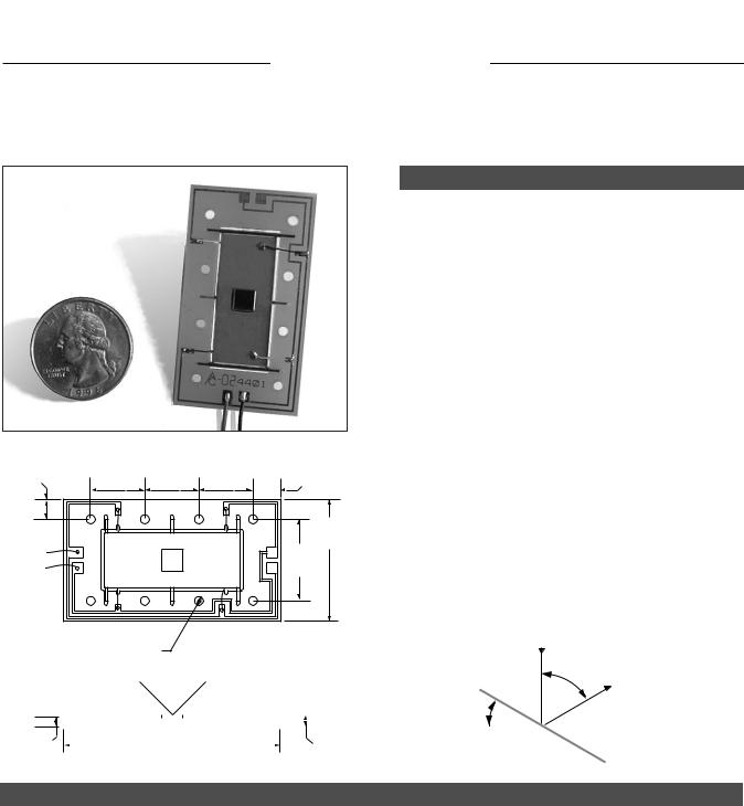
DESCRIPTION
The Piezo Mirror Tilters are low profile (~2.6 mm), light weight (~6 grams), high frequency devices designed for dynamic angular positioning at low power. These devices are capable of being directly bolted to gimbal mounts to replace bulky galvanometer systems. The piezoelectric motors deliver optical angles from ± 6 to ± 16 milliradians, while providing the fine resolution associated with piezoelectric devices. The tilter has very low magnetic permeability and produces no magnetic fields.
A 5mm square x 1mm thick crown glass mirror with a protected aluminium coating is attached to the tilter assembly (protected gold mirror option available). However, the customer may define or supply the optic to be attached.
.188 |
.500 |
.500 |
.500 |
.250 |
4.76 |
12.7 |
12.7 |
12.7 |
6.34 |
|
|
|
|
1.125 |
|
|
|
|
28.5 |
_ |
|
|
|
.750 |
|
|
|
19.0 |
|
+ |
|
|
|
Ø.086 DIA. CLR HOLES FOR #2-56 BOLTS
.093 |
− β |
|
+ β |
|
|
|
|
|||||
|
|
|
|
|
||||||||
|
|
|
|
|
|
|
|
|
|
|
|
|
|
|
|
|
|
|
|
|
|
|
|
|
|
|
|
|
|
|
|
|
|
|
|
|
|
|
|
|
2.00 |
|
|
|
.105 |
||||||
|
|
|
||||||||||
2.36 |
|
|
50.8 |
|
|
|
2.66 |
|||||
The tilter may be mounted to mechanical ground using the eight 2 mm or #2-56 clearance holes located around the periphery of the printed circuit board.
The tilter requires an electrical driver capable of supplying up to the maximum rated voltage to deliver full range angular motion. Piezo System’s EPA-104 Piezo Amplifier is suitable for driving the mirror tilters.
Custom configurations available upon request.
|
Beam |
β = 2 α |
|
In |
|
|
Optical |
|
|
Angle, β |
Beam |
|
|
Out |
Piezo |
|
|
Angle, α |
Mirror Surface |
|
|
|
|
SINGLE AXIS MIRROR TILTER PERFORMANCE
PART NUMBER |
WEIGHT |
CAPACITANCE |
RESONANT |
BROADBAND |
RATED |
|
OPTICAL |
ANGULAR |
|
|
|
|
FREQUENCY |
RANGE |
VOLTAGE |
|
ANGLE, β |
RESOLUTION |
|
|
grams |
nF |
Hz |
Hz |
±Vp |
± milliradians |
degrees |
µradians |
|
ΙAG1-A4CL-315H |
5.6 |
23 |
2,250 |
0 - 1,000 |
± 120 |
± 16.5 |
± .95 |
3.3 |
|
ΙAG1-A4CL-319H |
5.9 |
16 |
3,000 |
0 - 1,350 |
± 180 |
± 12.9 |
± .74 |
2.6 |
|
ΙAG1-A4CL-323H |
6.0 |
16 |
3,800 |
0 - 1,700 |
± 180 |
± |
9.7 |
± .55 |
1.9 |
ΙAG1-A4CL-323F |
6.1 |
16 |
5,500 |
0 - 2,500 |
± 180 |
± |
6.1 |
± .35 |
1.2 |
|
|
|
|
|
|
|
|
|
|
ORDERING INFORMATION |
PART NO. |
1 pc. |
5 pc. |
25 pc. |
100 pc. |
|
1- Axis Mirror Tilter, |
± .95° |
ΙAG1-A4CL-315H |
$999 |
$749 |
$549 |
$399 |
1- Axis Mirror Tilter, |
± .74° |
ΙAG1-A4CL-319H |
$999 |
$749 |
$549 |
$399 |
1- Axis Mirror Tilter, |
± .55° |
ΙAG1-A4CL-323H |
$999 |
$749 |
$549 |
$399 |
1- Axis Mirror Tilter, |
± .35° |
ΙAG1-A4CL-323F |
$999 |
$749 |
$549 |
$399 |
CATALOG #6, 2005 |
10 |