

Recommended serial interface for transceiver control V1.0a
.pdfSerial Interface for Transceiver Control
Infrared Data Association
RECOMMENDED SERIAL INTERFACE
FOR TRANSCEIVER CONTROL
Version 1.0a
March 29, 2000
1

Serial Interface for Transceiver Control
Author:
Franco Iacobelli (National Semiconductor Corporation)
Significant Contributors:
John Petrilla, Takashi Hidai (Agilent Technologies Inc.)
Bryn Owen, Patrick Kam (IBM Corporation)
Ray Chock (Calibre Inc.)
Revision:
March 8, 2000 Table 3-1 |
Add Rohm to the manufacturers table with ID number OAh. |
2

Serial Interface for Transceiver Control
INFRARED DATA ASSOCIATION (IrDA) - NOTICE TO THE TRADE -
SUMMARY:
Following is the notice of conditions and understandings upon which this document is made available to members and nonmembers of the Infrared Data Association.
∙Availability of Publications, Updates and Notices
∙Full Copyright Claims Must be Honored
∙Controlled Distribution Privileges for IrDA Members Only
∙Trademarks of IrDA - Prohibitions and Authorized Use
∙No Representation of Third Party Rights
∙Limitation of Liability
∙Disclaimer of Warranty
∙Product Testing for IrDA Specification Conformance
IrDA PUBLICATIONS and UPDATES:
IrDA publications, including notifications, updates, and revisions, are accessed electronically by IrDA members in good standing during the course of each year as a benefit of annual IrDA membership. Electronic copies are available to the public on the IrDA web site located at irda.org. Requests for publications, membership applications or more information should be addressed to:
Infrared Data Association, P.O. Box 3883, Walnut Creek, California, U.S.A. 94598; or e-mail address: info@irda.org; or by calling
(925) 943-6546 or faxing requests to (925) 943-5600.
COPYRIGHT:
1.Prohibitions: IrDA claims copyright in all IrDA publications. Any unauthorized reproduction, distribution, display or modification, in whole or in part, is strictly prohibited.
2.Authorized Use: Any authorized use of IrDA publications (in whole or in part) is under NONEXCLUSIVE USE LICENSE ONLY. No rights to sublicense, assign or transfer the license are granted and any attempt to do so is void.
TRADEMARKS:
1.Prohibitions: IrDA claims exclusive rights in its trade names, trademarks, service marks, collective membership marks and feature trademark marks (hereinafter collectively "trademarks"), including but not limited to the following trademarks: INFRARED DATA ASSOCIATION (wordmark alone and with IR logo), IrDA (acronym mark alone and with IR logo), IR logo and MEMBER IrDA (wordmark alone and with IR logo). Any unauthorized use of IrDA trademarks is strictly prohibited.
2.Authorized Use: Any authorized use of an IrDA collective membership mark or feature trademark is by NONEXCLUSIVE USE LICENSE ONLY. No rights to sublicense, assign or transfer the license are granted and any attempt to do so is void.
NO REPRESENTATION of THIRD PARTY RIGHTS:
IrDA makes no representation or warranty whatsoever with regard to IrDA member or third party ownership, licensing or infringement/non-infringement of intellectual property rights. Each recipient of IrDA publications, whether or not an IrDA member, should seek the independent advice of legal counsel with regard to any possible violation of third party rights arising out of the use, attempted use, reproduction, distribution or public display of IrDA publications.
3

Serial Interface for Transceiver Control
IrDA assumes no obligation or responsibility whatsoever to advise its members or non-members who receive or are about to receive IrDA publications of the chance of infringement or violation of any right of an IrDA member or third party arising out of the use, attempted use, reproduction, distribution or display of IrDA publications.
LIMITATION of LIABILITY:
BY ANY ACTUAL OR ATTEMPTED USE, REPRODUCTION, DISTRIBUTION OR PUBLIC DISPLAY OF ANY IrDA PUBLICATION,
ANY PARTICIPANT IN SUCH REAL OR ATTEMPTED ACTS, WHETHER OR NOT A MEMBER OF IrDA, AGREES TO ASSUME
ANY AND ALL RISK ASSOCIATED WITH SUCH ACTS, INCLUDING BUT NOT LIMITED TO LOST PROFITS, LOST SAVINGS, OR OTHER CONSEQUENTIAL, SPECIAL, INCIDENTAL OR PUNITIVE DAMAGES. IrDA SHALL HAVE NO LIABILITY WHATSOEVER FOR SUCH ACTS NOR FOR THE CONTENT, ACCURACY OR LEVEL OF ISSUE OF AN IrDA PUBLICATION.
DISCLAIMER of WARRANTY:
All IrDA publications are provided "AS IS" and without warranty of any kind. IrDA (and each of its members, wholly and collectively, hereinafter "IrDA") EXPRESSLY DISCLAIM ALL WARRANTIES, EXPRESS OR IMPLIED, INCLUDING BUT NOT LIMITED TO, THE
IMPLIED WARRANTIES OF MERCHANTABILITY AND FITNESS FOR A PARTICULAR PURPOSE AND WARRANTY OF NONINFRINGEMENT OF INTELLECTUAL PROPERTY RIGHTS.
IrDA DOES NOT WARRANT THAT ITS PUBLICATIONS WILL MEET YOUR REQUIREMENTS OR THAT ANY USE OF A
PUBLICATION WILL BE UN-INTERRUPTED OR ERROR FREE, OR THAT DEFECTS WILL BE CORRECTED.
FURTHERMORE, IrDA DOES NOT WARRANT OR MAKE ANY REPRESENTATIONS REGARDING USE OR THE RESULTS OR
THE USE OF IrDA PUBLICATIONS IN TERMS OF THEIR CORRECTNESS, ACCURACY, RELIABILITY, OR OTHERWISE. NO ORAL OR WRITTEN PUBLICATION OR ADVICE OF A REPRESENTATIVE (OR MEMBER) OF IrDA SHALL CREATE A
WARRANTY OR IN ANY WAY INCREASE THE SCOPE OF THIS WARRANTY.
LIMITED MEDIA WARRANTY:
IrDA warrants ONLY the media upon which any publication is recorded to be free from defects in materials and workmanship under normal use for a period of ninety (90) days from the date of distribution as evidenced by the distribution records of IrDA. IrDA's entire liability and recipient's exclusive remedy will be replacement of the media not meeting this limited warranty and which is returned to
IrDA. IrDA shall have no responsibility to replace media damaged by accident, abuse or misapplication. ANY IMPLIED
WARRANTIES ON THE MEDIA, INCLUDING THE IMPLIED WARRANTIES OF MERCHANTABILITY AND FITNESS FOR A
PARTICULAR PURPOSE, ARE LIMITED IN DURATION TO NINETY (90) DAYS FROM THE DATE OF DELIVERY. THIS
WARRANTY GIVES YOU SPECIFIC LEGAL RIGHTS, AND YOU MAY ALSO HAVE OTHER RIGHTS WHICH VARY FROM PLACE TO PLACE.
COMPLIANCE and GENERAL :
Membership in IrDA or use of IrDA publications does NOT constitute IrDA compliance. It is the sole responsibility of each manufacturer, whether or not an IrDA member, to obtain product compliance in accordance with IrDA Specifications.
All rights, prohibitions of right, agreements and terms and conditions regarding use of IrDA publications and IrDA rules for compliance of products are governed by the laws and regulations of the United States. However, each manufacturer is solely responsible for compliance with the import/export laws of the countries in which they conduct business. The information contained in this document is provided as is and is subject to change without notice.
4

Serial Interface for Transceiver Control
1.1 OVERVIEW
This document describes a simple serial interface that allows an infrared controller to communicate with one or more infrared transceivers. This interface requires three signals: a clock line that is used for timing, and two unidirectional lines multiplexed with the transmitter (write) and receiver (read) infrared signal lines. The main features of the serial interface are listed below.
-Message Based
-Low Power Consumption
-High Speed
-Simple Protocol
-Bus protocol implemented in hardware or in software through bit banging.
-Read and write capability
-Open Architecture (not patented)
-Easily Expandable
1.2 BASIC CONFIGURATIONS
There are two basic system configurations using the serial interface. The first one is found in portable computers and most embedded systems. In this case two optical transceivers are typically used; one in the front and one in the rear of the system’s chassis. Furthermore, the infrared controller and transceivers are in close proximity of one another. The interconnections are usually implemented with single ended signals since their contribution to EMI is minimal. Handling multiple optical transceivers is easily accomplished by assigning them different addresses. The second configuration exists typically in desktop systems. In this case only one transceiver is required. The transceiver is usually mounted on a tiny PC board and communicates with the infrared controller through a shielded cable approximately 1.5 m long. This PC board and cable assembly is commonly referred to as Infrared Dongle. Currently existing Dongles use single ended signaling. However, due to the inherent EMI problems of this arrangement, there is a strong incentive in future Dongles to use differential signaling.
|
|
OFE A |
|
|
|
IRTX/SWDAT |
TX/SWDAT |
|
|
|
IRRX/SRDAT |
|
||
Infrared |
RX/SRDAT |
Optical |
||
SCLK |
||||
|
||||
Controller |
SCLK |
Transceiver |
||
|
||||
|
GND |
A_SL |
|
|
|
VCC |
|
|
OFE B
TX/SWDAT |
|
RX/SRDAT |
Optical |
SCLK |
Transceiver |
VCC A_SL |
|
Figures 1-1 and 1-2 below show two typical transceiver configurations.
Figure 1-1. Interface to Two Infrared Transceivers.
The data lines are multiplexed with the transmitter and receiver signals and a different address for each transceiver can be selected.
The pullup resistor on the IRRX/SRDAT line is used to prevent spurious low-going transitions during the time in which both transceivers are disabled. When no infrared communication is in progress and the serial interface is
5

Serial Interface for Transceiver Control
idle, the IRTX/SWDAT line is kept low and IRRX/SRDAT is kept high.
|
Connector |
Shielded Cable |
|
LVDS |
|
|
|
VCC |
|
VCC |
Transceiver |
|
|
|
|
|
|
|
||
|
GND |
|
GND |
|
|
|
|
IRTX+/SWDAT+ |
|
|
|
TX/SWDAT |
|
|
IRTX-/SWDAT- |
|
|
|
|
|
Infrared |
IRRX+/SRDAT+ |
|
|
|
RX/SRDAT |
Optical |
Controller |
IRRX-/SRDAT- |
|
|
|
||
|
SCLK+ |
|
|
|
|
Transceiver |
|
SCLK- |
|
|
|
SCLK |
|
|
|
|
|
GND |
A_SL |
|
Figure 1-2. Infrared Dongle with Differential Signaling.
1.3 FUNCTIONAL DESCRIPTION
The serial interface is designed to interconnect two or more devices. One of the devices is always in control of the serial interface and is responsible for starting every transaction. This device functions as the bus master and is always the infrared controller. The infrared transceivers act as bus slaves and only respond to transactions initiated by the master. A bus transaction is made up of one or two phases. The first phase is the Command Phase and is present in every transaction. The second phase is the Response Phase and is present only in those transactions in which data must be returned from the slave. If the operation involves a data transfer from the slave, there will be a Response Phase following the Command Phase in which the slave will output the data.
The start bit of the slave response, if present, must occur 4 clock cycles after the last bit of the Command Phase, as shown in figures 1-8 and 1-9, otherwise it is assumed that there will be no response. The master must always complete the transaction normally. More precisely, it must not stop the clock and terminate the transaction earlier if the slave does not respond.
The SCLK line is always driven by the master and is used to clock the data being written to or read from the slave. This line is driven by a totem-pole output buffer. The SCLK line is always stopped when the serial interface is idle to minimize power consumption and to avoid any interference with the analog circuitry inside the slave. There are no gaps between the bytes in either the Command or Response Phase. Each byte of data in both Command and Response Phases is preceded by one start bit. Data is always transferred in Little Endian order (least significant bit first). Input data is sampled on the rising edge of SCLK. Output data from the controller is clocked by SCLK falling edge. Output data from the slave is clocked by SCLK rising edge. This makes the interface signaling less sensitive to timing skews. Figure 1-3 shows the interface timing including the data sampling points.
The data to be written to the slave is carried on the IRTX/SWDAT line. When the control interface is idle, this line carries the infrared data signal used to drive the transmitter LED. When the first low-to-high transition on SCLK is detected at the beginning of the command sequence, the slave will disable the transmitter LED. The infrared controller then outputs the command string on the IRTX/SWDAT line. On the last SCLK cycle of the command sequence the slave re-enables the transmitter LED and normal infrared transmission can resume. No transition on SCLK must occur until the next command sequence, otherwise the slave will disable the transmitter LED again. Read data is carried on the IRRX/SRDAT line. The slave disables the internal signal from the receiver photo diode during the response phase of a read transaction. The addressed slave will output the read data on the IRRX/SRDAT line regardless of the setting of the Receiver Output Enable bit in the Mode Selection register 0. Non addressed slaves will tri-state the IRRX/SRDAT line. When the transceiver is powered up, the IRTX/SWDAT line should be kept low and SCLK should be cycled at least 30 times by the infrared controller before the first command is issued on the IRTX/SWDAT line. This guarantees that the transceiver interface circuitry will properly initialize and be ready to receive commands from the controller (note 1). In case of a multiple transceiver configuration, only one transceiver should have the receiver output enabled. If these transceivers are connected to the infrared controller via short traces (like in a notebook computer), a series resistor (approx. 200 ohms) should be placed on the receiver output from each transceiver to prevent large currents in case a conflict occurs due to a programming error.
Note 1: Since there is no reset line, the serial interface can be initialized by implementing a self-resetting interface state machine in the transceiver. This machine must be guaranteed to
6

Serial Interface for Transceiver Control
transition to the idle state by cycling the SCLK line at least 30 times while keeping IRTX low.
It is only from the idle state that the transceiver state machine can correctly accept a command from the infrared controller.
Figures 1-4 to 1-9 show the waveforms for the various serial interface operations.
CLOCK SIGNAL
GENERATED BY THE
INFRARED CONTROLLER
CLOCK SIGNAL
RECEIVED BY THE
INFRARED TRANSCEIVER
WRITE DATA
OUTPUT BY THE
INFRARED CONTROLLER
WRITE DATA
SAMPLED BY THE
INFRARED TRANSCEIVER
READ DATA
OUTPUT BY THE
INFRARED TRANSCEIVER
READ DATA
SAMPLED BY THE
INFRARED CONTROLLER
Figure 1-3. Serial Interface Timing.
This figure shows the signal delays due to the cable as well as the data sampling points for both the infrared controller and transceiver.
 30 CLOCK CYCLES
SCLK |
IRTX/ |
SWDAT |
IRRX/ |
SRDAT |
TLED_DIS |
(INTERNAL SIGNAL) |
Figure 1-4. Initial Reset Timing
7

Serial Interface for Transceiver Control
START |
ADDRESS & CONTROL |
SCLK |
IRTX/ |
SWDAT |
IRRX/ |
SRDA |
TLED_DIS |
(INTERNAL SIGNAL) |
RES |
(INTERNAL SIGNAL) |
Figure 1-5. Special Command Waveform
START |
ADDRESS, INDEX, DIR. |
START |
DATA |
SCLK |
|
|
|
IRTX/ |
|
|
|
SWDAT |
|
|
|
IRRX/ |
|
|
|
SRDAT |
|
|
|
TLED_DIS |
|
|
|
(INTERNAL SIGNAL) |
|
|
|
RES |
|
|
|
(INTERNAL SIGNAL) |
|
|
|
Figure 1-6. Write Data Waveform.
Note 2: If the APEN bit in control register 0 is set to 1, the internal signal from the receiver photo diode is disconnected and the IRRX/SRDAT line from the addressed transceiver is pulsed low for one clock cycle at the end of a write or special command. No pulse is generated if a broadcast address is used.
8

Serial Interface for Transceiver Control
START |
ADDRESS, DIR. |
START |
EXT. INDEX |
START |
DATA |
SCLK |
|
|
|
|
|
IRTX/ |
|
|
|
|
|
SWDAT |
|
|
|
|
|
IRRX/ |
|
|
|
|
|
SRDAT |
|
|
|
|
|
TLED_DIS |
|
|
|
|
|
(INTERNAL SIGNAL) |
|
|
|
|
|
RES |
|
|
|
|
|
(INTERNAL SIGNAL) |
|
|
|
|
|
Figure 1-7. Write Data Waveform with Extended Index.
START |
ADDRESS, INDEX, DIR. |
START |
DATA |
SCLK |
|
|
|
IRTX/ |
|
|
|
SWDAT |
|
|
|
IRRX/ |
|
|
|
SRDAT |
|
|
|
RX_EN |
|
|
|
(INTERNAL SIGNAL) |
|
|
|
RX_DIS |
|
|
|
(INTERNAL SIGNAL) |
|
|
|
TLED_DIS |
|
|
|
(INTERNAL SIGNAL) |
|
|
|
RES |
|
|
|
(INTERNAL SIGNAL) |
|
|
|
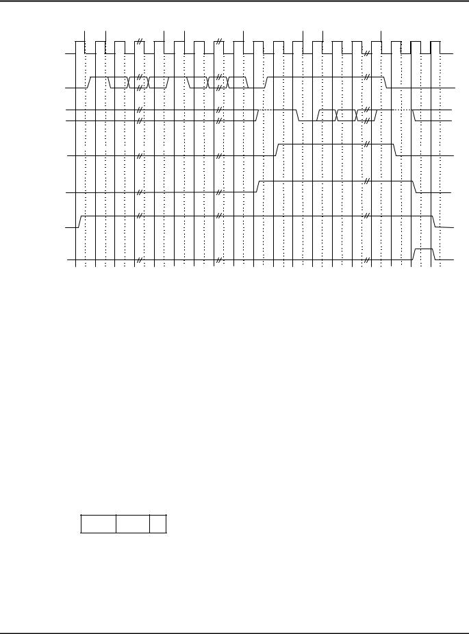
Figure 1-8. Read Data Waveform.
9
Serial Interface for Transceiver Control
START |
ADDRESS, DIR. |
START |
EXT. INDEX |
START |
DATA |
SCLK |
|
|
|
|
|
IRTX/ |
|
|
|
|
|
SWDAT |
|
|
|
|
|
IRRX/ |
|
|
|
|
|
SRDAT |
|
|
|
|
|
RX_EN |
|
|
|
|
|
(INTERNAL SIGNAL) |
|
|
|
|
|
RX_DIS |
|
|
|
|
|
(INTERNAL SIGNAL) |
|
|
|
|
|
TLED_DIS |
|
|
|
|
|
(INTERNAL SIGNAL) |
|
|
|
|
|
RES |
|
|
|
|
|
(INTERNAL SIGNAL) |
|
|
|
|
|
Figure 1-9. Read Data Waveform with Extended Index.
Note 3: During a read transaction the infrared controller sets the IRTX/SWDAT line low for one clock cycle after sending the address and index byte (or bytes). It will then set it high and low again three clock cycles before the end of the transaction.
It is strongly recommended that optical transceivers monitor this line
instead of counting clock cycles in order to detect the end of the read transaction.
This will always guarantee correct operation in case two or more transceivers from different manufacturers are sharing the serial interface.
2.0 BUS PROTOCOL
A set of commands is provided to handle the various transactions between the master and each of the slaves. The set is fully expandable to handle future requirements. The general command format is shown in figure 2-1. Data is transferred in little endian order, bit 0 of byte 0 is the first bit transferred, bit 7 of byte 2 is the last.
7
ADDR INDX
BYTE 0
0
C
7 |
0 |
7 |
0 |
|
DATA or E_INDX |
|
|
DATA |
|
|
|
|
|
|
|
BYTE 1 |
|
|
BYTE 2 |
Figure 2-1. General Command Format.
The first byte, common to all transactions, contains the address of the slave to be accessed and two control fields. The first control field is the INDX field. It determines whether the transaction is a Special Transaction or a Data Transaction. The second control field (C field) consists of only one bit and either determines the data transfer direction or it further qualifies a special transaction. The second byte is present in read and write transactions.
10