

Rocket serial link interconnection standard.2003
.pdfUnit / Module Name: |
|
Rocket Serial Link |
|
|
|
Unit / Module Number: |
|
RSL |
|
|
|
Used On: |
|
TIM Modules / Carriers |
|
|
|
Document Issue: |
|
1.3 |
|
|
|
Date: |
|
08/09/2003 |
|
|
|
|
CONFIDENTIAL |
|
Rocket Serial Link
Interconnection Standard
Outstanding Issues:
1)Sundance to provide additional information for Appendix A
2)Completion of Section 4 (MRV)
3)Completion of Section 5 (MRV)
Approvals |
Date |
Managing Director
Software Manager
Design Engineer
Sundance Multiprocessor Technology Ltd, Chiltern House, Waterside, Chesham, Bucks. HP5 1PS. This document is the property of Sundance and may not be copied nor communicated to a third party without the written permission of Sundance. © Sundance Multiprocessor Technology Limited 1999
Revision History
Date |
Changes Made |
Rev |
Issue |
Initials |
|
|
|
|
|
02/05/03 |
First release |
01 |
01 |
MRV |
|
|
|
|
|
08/09/03 |
General Updates to Document |
01 |
02 |
MRV |
|
|
|
|
|
15/09/03 |
Changed orientation of RSL Connectors |
01 |
03 |
MRV |
|
|
|
|
|
List of Abbreviations
Abbreviation |
Explanation |
|
|
CDR |
Clock and Data Recovery |
|
|
FPGA |
Field Programmable Gate Array |
|
|
LVDS |
Low Voltage Differential Signalling |
|
|
MGT |
Multi-Gigabit Transceiver |
|
|
RSL |
Rocket Serial Link |
|
|
RSLCC |
Rocket Serial Link Communications Channel |
|
|
SHB |
Sundance High-speed Bus |
|
|
SI |
Serial Interface |
|
|
SMT |
Sundance Multiprocessor Technology |
|
|
TBD |
To Be Determined |
|
|
Table of Contents
1 |
Introduction ...................................................................................................................... |
|
6 |
||
|
1.1 |
Overview..................................................................................................................... |
|
6 |
|
|
1.2 |
RSL Features ............................................................................................................. |
6 |
||
|
1.3 |
Related Documents.................................................................................................... |
6 |
||
2 |
Mechanical Specifications .............................................................................................. |
7 |
|||
|
2.1 |
Connector Type.......................................................................................................... |
7 |
||
|
2.2 |
RSL Connector Location............................................................................................ |
8 |
||
|
2.2.1 |
RSL Compliant TIM Modules ............................................................................. |
8 |
||
|
2.2.2 |
RSL Compliant TIM Carriers............................................................................ |
10 |
||
|
2.2.3 |
Rigid Printed Circuit Boards ............................................................................. |
10 |
||
|
2.2.4 |
Cable Assemblies............................................................................................. |
11 |
||
|
2.3 |
RSL Connector Type / Location............................................................................... |
13 |
||
|
2.4 |
Connector Pin-outs .................................................................................................. |
14 |
||
|
2.4.1 |
Naming Convention.......................................................................................... |
14 |
||
|
2.4.2 |
Tim Module....................................................................................................... |
14 |
||
|
|
2.4.2.1 RSL Type A, Top, 4 Links, TIM.................................................................... |
15 |
||
|
|
2.4.2.2 RSL Type B, Top, 4 Links, TIM.................................................................... |
15 |
||
|
|
2.4.2.3 RSL Type A, Top, 8 Links, TIM.................................................................... |
16 |
||
|
|
2.4.2.4 RSL Type B, Top, 8 Links, TIM.................................................................... |
16 |
||
|
|
2.4.2.5 RSL Type A, Top, 12 Links, TIM.................................................................. |
17 |
||
|
|
2.4.2.6 RSL Type B, Top, 12 Links, TIM.................................................................. |
17 |
||
|
|
2.4.2.7 RSL Type A, Bottom, 4 Links, TIM .............................................................. |
18 |
||
|
|
2.4.2.8 RSL Type B, Bottom, 4 Links, TIM .............................................................. |
18 |
||
|
|
2.4.2.9 RSL Type A, Bottom, 8 Links, TIM .............................................................. |
19 |
||
|
|
2.4.2.10 |
RSL Type B, Bottom, 8 Links, TIM .......................................................... |
19 |
|
|
|
2.4.2.11 |
RSL Type A, Bottom, 12 Links, TIM ........................................................ |
20 |
|
|
|
2.4.2.12 |
RSL Type B, Bottom, 12 Links, TIM ........................................................ |
20 |
|
|
2.4.3 |
Carrier............................................................................................................... |
21 |
||
|
|
2.4.3.1 RSL Type A, 4 Links, Carrier ....................................................................... |
23 |
||
|
|
2.4.3.2 RSL Type B, 4 Links, Carrier ....................................................................... |
23 |
||
|
|
2.4.3.3 RSL Type A, 8 Links, Carrier ....................................................................... |
24 |
||
|
|
2.4.3.4 RSL Type B, 8 Links, Carrier ....................................................................... |
24 |
||
|
|
2.4.3.5 RSL Type A, 12 Links, Carrier ..................................................................... |
25 |
||
|
|
2.4.3.6 RSL Type B, 12 Links, Carrier ..................................................................... |
25 |
||
|
2.4.4 |
Rigid PCB and RSL Cable ............................................................................... |
26 |
||
|
|
2.4.4.1 RSL Type A, Top, Rigid PCB....................................................................... |
27 |
||
|
2.4.4.2 RSL Type B, Top, Rigid PCB....................................................................... |
27 |
|
|
2.4.4.3 RSL Type A, Top, Inter-connecting Cable ................................................... |
28 |
|
|
2.4.4.4 RSL Type B, Top, Inter-connecting Cable ................................................... |
28 |
|
3 Xilinx Multi-gigabit Transceivers.................................................................................. |
29 |
||
3.1 |
Supported Devices ................................................................................................... |
29 |
|
3.2 |
RocketIO Features[B] ................................................................................................ |
29 |
|
3.3 |
The Xilinx MGT Core................................................................................................ |
30 |
|
3.3.1 |
Clock Synthesizer[A].......................................................................................... |
31 |
|
3.3.2 |
Clock and Data Recovery[A] ............................................................................. |
31 |
|
3.3.3 |
FPGA Transmit Interface[B] .............................................................................. |
31 |
|
3.3.48B/10B Encoder[A],............................................................................................ 31
3.3.5 |
Transmit FIFO[A] ............................................................................................... |
31 |
|
3.3.6 |
Serializer[A] ........................................................................................................ |
31 |
|
3.3.7 |
Transmit Termination[A] .................................................................................... |
32 |
|
3.3.8 |
Pre-Emphasis and Swing Control[A] ................................................................. |
32 |
|
3.3.9 |
Deserializer[A].................................................................................................... |
32 |
|
3.3.10 |
Comma Detect[A]............................................................................................... |
32 |
|
3.3.11 |
Receive Termination[A] ..................................................................................... |
32 |
|
3.3.12 |
8B/10B Decoder[A] ............................................................................................ |
32 |
|
3.3.13 |
Receive Buffer[A] ............................................................................................... |
32 |
|
3.3.14 |
Transmit Buffer[A] .............................................................................................. |
33 |
|
3.3.15 |
CRC[A] ............................................................................................................... |
33 |
|
3.4 |
Reference Clock....................................................................................................... |
33 |
|
3.5 |
RSL Specific Implementations ................................................................................. |
33 |
|
3.5.1 |
VHDL Instantiation ........................................................................................... |
33 |
|
3.5.2 |
Hardware implementation ................................................................................ |
33 |
|
4 Electrical Specifications................................................................................................ |
34 |
||
4.1 |
Signaling Level......................................................................................................... |
34 |
|
4.2 |
PCB Design Consideration ...................................................................................... |
34 |
|
4.2.1 |
Routing of differential pairs .............................................................................. |
34 |
|
4.2.2 |
Example PCB Layer Stack............................................................................... |
34 |
|
5 Generic VHDL Building Blocks .................................................................................... |
34 |
||
6 Appendix A: Sundance RSL Compliant Modules....................................................... |
34 |
||
Table of Figures |
|
||
Figure 1 –RSL QSE-014-xx-DP Type Connector...................................................................... |
7 |
||
Figure 2 –RSL QTE-014-xx-DP Type Connector ...................................................................... |
7 |
||
Figure 3 –QSE / QTE Connector Characteristics...................................................................... |
7 |
||
Figure 4 – Full RSL Connector Part Numbers........................................................................... |
8 |
||
Figure 5 – Location of RSL Connectors on Top of TIM Module................................................ |
9 |
||
Figure 6 |
– Location of RSL Connectors on Bottom of TIM Module. ......................................... |
9 |
|
Figure 7 |
– Location of RSL Connectors on Carrier TIM Site. ................................................. |
10 |
|
Figure 8 |
– Joining two adjacent TIM modules......................................................................... |
11 |
|
Figure 9 |
– RSL High Speed Data Link Cable. ......................................................................... |
11 |
|
Figure 10 – HFEM Cable Characteristics................................................................................ |
12 |
||
Figure 11 – RSL Connector Type and Position ....................................................................... |
13 |
||
Figure 12 – RSL Prefix Explanation......................................................................................... |
13 |
||
Figure 13 – RSL Naming Convention ...................................................................................... |
14 |
||
Figure 14 – Top and Bottom RSL Connector on TIM Module................................................. |
21 |
||
Figure 15 |
– RSL Connection between TIM Module and Carrier ............................................. |
22 |
|
Figure 16 |
– Rigid PCB Pin Assignments ................................................................................. |
26 |
|
Figure 17 |
– Xilinx Devices Supporting RocketIO .................................................................... |
29 |
|
Figure 18 |
– The Xilinx Multi-Gigabit Transceiver Core[B] ......................................................... |
30 |
|
1 Introduction
1.1Overview
The Rocket Serial Link (RSL) is a serial interconnection standard that is capable of data transfer speeds of up to 2.5GBit/s per serial link. Up to four of these links can be combined to form a Rocket Serial Link Communications Channel (RSLCC) that is capable of data transfer up to 10GBit/s.
Each RSL is made up of a differential Transmit and Receive pair. A single Rocket Serial Link is thus a full-duplex link and can transfer data at up to 2.5GBit/s in either direction at the same time. The transmission clock is recovered from the data stream, leaving the link as a fully independent communications link that requires no additional control or data signals.
The RSL standard is based on the RocketIO transceiver core found on Xilinx Virtex-II Pro FPGAs. These silicon integrated transceiver cores handle the serialization / de-serialization of the data stream as well as certain low level management functions.
This document describes various aspects of the Rocket Serial Link (RSL). It covers the mechanical specifications for the standard, including the connector types, position and pinouts. It covers the electrical characteristics of the interconnection standard as well as certain standard VHDL building blocks.
The RSL specification defines all the aspects of how to interconnect Sundance modules in a standard way using the integrated RocketIO transceivers in the Xilinx Virtex-II Pro devices. The RocketIO transceivers are not limited for use with Sundance RSL compliant hardware only. These transceivers, with adequate physical layers, may be used form many different serial interconnection standards. These standards include RapidIO, Infiniband, Serial ATA and Gigabit Ethernet. For more information refer to the Xilinx documentation on RocketIO [1,2]
1.2RSL Features
∙Full Duplex Communication per RSL
∙Data transfer at up to 2.5GBit/s (To be confirmed by hardware characterization) per RSL
∙Grouping of up to four RSL to form a single 10GBit/s link
∙Low Voltage Differential Signaling used
∙Full clock recovery from data stream
∙Compatibility with emerging serial interconnection standards
1.3Related Documents
[1]Virtex-II Pro Datasheet, ds083.pdf – Xilinx
[2]RocketIO Transceiver User Guide, ug024.pdf - Xilinx
[3]SMT398-Pro Specification – Sundance.

2 Mechanical Specifications
2.1Connector Type
The RSL connectors used on the TIM modules and Carriers are 0.8mm pitch differential Samtec connectors. Any single connector makes provision for a maximum of 14 differential pairs. The Samtec QSE-014-xx-DP and QTE-014-xx-DP type of connectors are used on both the TIM modules and the Carriers.
The following two diagrams show the Top View of the QSE and QTE type connectors.
Figure 1 –RSL QSE-014-xx-DP Type Connector
Figure 2 –RSL QTE-014-xx-DP Type Connector
Both connectors have a single pin omitted on either side of the connector after every second pin. This architecture creates 14 individual differential pairs in the connector with proper isolation between pairs. The connector also contains a solid integrated ground plain in the middle throughout the full length of the connector. This provides addition shielding to the differential pairs. The connector characteristics for a 5.03mm QSE/QTE connector stack is given in the following table:
Impedance Mismatch (Ohm) |
|
Near End Cross Talk |
||
|
|
|
|
|
Period |
Impedance |
|
Frequency |
Percentage |
|
|
|
|
|
30 ps |
111.6 to 88.0 |
|
6.40 GHz |
~1.75% |
|
|
|
|
|
50 ps |
103.6 to 94.0 |
|
10.00 GHz |
~2.0% |
|
|
|
|
|
100 ps |
98.8 to 98.2 |
|
|
|
|
|
|
|
|
250 ps |
100.0 to 99.6 |
|
|
|
|
|
|
|
|
Figure 3 –QSE / QTE Connector Characteristics
The connectors are keyed to ensure correct insertion. The default QSE/QTE stacking height is 5.03 mm. The following stacking heights are also available: 8.03mm, 11.03mm, 16.00mm, 19.00mm, 22.00mm. The QSE connector always stays the same height. The QTE connector determines the stacking height.
The table underneath list the preferred TIM module and Carrier connector part numbers for a stacking height of 5.03mm. A description of which connectors are used where is provided in the following section.
No |
Connector Description |
Document Reference |
Samtec Part Number |
|
|
|
|
1 |
TIM and Carrier RSL Type A Connector |
QSE-014-xx-DP |
QSE-014-01-F-D-DP-A |
|
|
|
|
2 |
TIM and Carrier RSL Type B Connector |
QTE-014-xx-DP |
QTE-014-01-F-D-DP-A |
|
|
|
|
Figure 4 – Full RSL Connector Part Numbers
More information about the QSE-014-xx-DP or QTE-014-xx-DP connectors please visit the Samtec website.
2.2RSL Connector Location
Unlike the SHB, the RSL signals are not bi-directional. To prevent inadvertent connection from Tx to Tx (and Rx to Rx), different connector genders with different signal assignments are used. There are two sets of signal assignments – RSL Type A assignments and RSL Type B assignments. When interconnecting RSL pairs RSL Type A must always interface to RSL Type B and visa versa. The RSL Type A Connector is the Samtec QSE-014-01-F-D-DP- A and the RSL Type B Connector is the Samtec QTE-014-01-F-D-DP-A. It is however possible for similar connectors in the same group to have different pin-outs, depending on the connectors location.
A single RSL is bi-directional. The RSL Type A signal group and the RSL Type B signal group thus contains a certain amount of bi-directional links each. RSL Type A links should not be confused as outputs only and RSL Type B links as inputs only.
2.2.1RSL Compliant TIM Modules
On a TIM module the RSL connectors replace the optional second set of SHB connectors. Next to the SHB-A connector the RSL Type A connector is located. This connector is a QSE- 014-xx-DP type connector. Next to the SHB-B connector the RSL Type B connector is located. This connector is a QTE-014-xx-DP type connector. These two connectors are located on the Top of the TIM Module and are ideal for module to module inter-connection. Identical connectors, but with a different pin-out, are located right underneath the RSL Type A and RSL Type B connectors. This set of connectors makes it possible to connect a RSL between a TIM module and a carrier without having to route the signals through a cable.
A Tim module thus contains two sets of two RSL connectors. Each set contains one connector on the Top of the module, and one on the Bottom of the module. The RSL Type A connector is a QSE type connector, and the RSL Type B connector is a QTE connector.
The following two diagrams shows the exact location of the RSL Type A and RSL Type B connectors on the Top and Bottom of a TIM module.

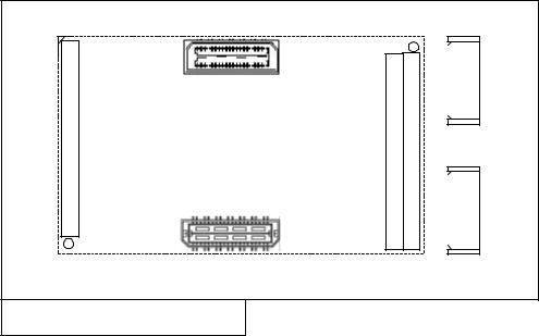
Figure 5 – Location of RSL Connectors on Top of TIM Module.
Figure 6 – Location of RSL Connectors on Bottom of TIM Module.
2.2.2RSL Compliant TIM Carriers
All RSL compliant carriers contain only two RSL connectors per TIM site. One RSL Type B QTE connector to mate with the RSL Type A QSE connector on the TIM module, and one RSL Type A QSE connector to mate with the RSL Type B QTE connector.
The exact mechanics of the connector placement may vary from carrier to carrier. For this reason only a diagram depicting the location of the RSL Type A and B Connectors in relation to the TIM site is shown in the following diagram:
Top Primary TIM Connector |
Type B RSL Type A |
QTE QSE |
TIM SITE |
Global Bus Connector |
Bottom Primary TIM Connector |
Connector SHB Connector |
|
RSL |
|
|
|
|
SHB |
PCI Interface |
|
|
|
|
|
|
Figure 7 – Location of RSL Connectors on Carrier TIM Site.
Future RSL Compliant Carriers may expand the RSL standard to include industry standard connectors for interfaces such as RapidIO, SATA, Inifiband and Gigabit Ethernet. In general the design impact of conforming to one of the above mentioned standards is very small on the hardware side, but rather large on the firmware and software side. The Xilinx Virtex-II Pro RocketIO transceivers are compatible with the above mentioned standards.
2.2.3Rigid Printed Circuit Boards
Rigid Printed Circuit Boards may be used to interconnect two adjacent TIM Modules. When two TIM modules are placed side by side the RSL Type A connector from the one module is adjacent to the RSL Type B connector form the other. The Rigid PCB thus provides a RSL Type A-to-Type B bridge between the two modules. The Rigid PCB contains a RSL Type B connector to connect to the Module RSL Type A connector and visa-versa. The routing on the PCB is a straight through 1 to 1 routing.
The two diagram on the following page illustrates this concept. The notation used to describe the location and type of connector is explained in the following section: RSL Connector Type / Location.