

Ryer A.The light measurement handbook.1997
.pdf
|
Photopic |
Photopic |
Scotopic |
Scotopic |
λ |
Luminous |
lm / W |
Luminous |
lm / W |
nm |
Efficiency |
Conversion |
Efficiency |
Conversion |
|
|
|
|
|
380 |
0.000039 |
0.027 |
0.000589 |
1.001 |
390 |
.000120 |
0.082 |
.002209 |
3.755 |
400 |
.000396 |
0.270 |
.009290 |
15.793 |
410 |
.001210 |
0.826 |
.034840 |
59.228 |
420 |
.004000 |
2.732 |
.096600 |
164.220 |
430 |
.011600 |
7.923 |
.199800 |
339.660 |
440 |
.023000 |
15.709 |
.328100 |
557.770 |
450 |
.038000 |
25.954 |
.455000 |
773.500 |
460 |
.060000 |
40.980 |
.567000 |
963.900 |
470 |
.090980 |
62.139 |
.676000 |
1149.200 |
480 |
.139020 |
94.951 |
.793000 |
1348.100 |
490 |
.208020 |
142.078 |
.904000 |
1536.800 |
500 |
.323000 |
220.609 |
.982000 |
1669.400 |
507 |
.444310 |
303.464 |
1.000000 |
1700.000 |
510 |
.503000 |
343.549 |
.997000 |
1694.900 |
520 |
.710000 |
484.930 |
.935000 |
1589.500 |
530 |
.862000 |
588.746 |
.811000 |
1378.700 |
540 |
.954000 |
651.582 |
.650000 |
1105.000 |
550 |
.994950 |
679.551 |
.481000 |
817.700 |
555 |
1.000000 |
683.000 |
.402000 |
683.000 |
560 |
.995000 |
679.585 |
.328800 |
558.960 |
570 |
.952000 |
650.216 |
.207600 |
352.920 |
580 |
.870000 |
594.210 |
.121200 |
206.040 |
590 |
.757000 |
517.031 |
.065500 |
111.350 |
600 |
.631000 |
430.973 |
.033150 |
56.355 |
610 |
.503000 |
343.549 |
.015930 |
27.081 |
620 |
.381000 |
260.223 |
.007370 |
12.529 |
630 |
.265000 |
180.995 |
.003335 |
5.670 |
640 |
.175000 |
119.525 |
.001497 |
2.545 |
650 |
.107000 |
73.081 |
.000677 |
1.151 |
660 |
.061000 |
41.663 |
.000313 |
0.532 |
670 |
.032000 |
21.856 |
.000148 |
0.252 |
680 |
.017000 |
11.611 |
.000072 |
0.122 |
690 |
.008210 |
5.607 |
.000035 |
.060 |
700 |
.004102 |
2.802 |
.000018 |
.030 |
710 |
.002091 |
1.428 |
.000009 |
.016 |
720 |
.001047 |
0.715 |
.000005 |
.008 |
730 |
.000520 |
0.355 |
.000003 |
.004 |
740 |
.000249 |
0.170 |
.000001 |
.002 |
750 |
.000120 |
0.082 |
.000001 |
.001 |
760 |
.000060 |
0.041 |
|
|
770 |
.000030 |
0.020 |
|
|
|
|
|
|
|
31
Irradiance and Illuminance:
Irradiance is a measure of radiometric flux per unit area, or flux density. Irradiance is typically expressed in W/cm2 (watts per square centimeter) or W/m2 (watts per square meter).
Illuminance is a measure of photometric flux per unit area, or visible flux density. Illuminance is typically expressed in lux (lumens per square meter) or foot-candles (lumens per square foot).
In figure 7.4, above, the light bulb is producing 1 candela. The candela is the base unit in light measurement, and is defined as follows: a 1 candela light source emits 1 lumen per steradian in all directions (isotropically). A steradian is defined as the solid angle which, having its vertex at the center of the sphere, cuts off an area equal to the square of its radius. The number of steradians in a beam is equal to the projected area divided by the square of the distance.
So, 1 steradian has a projected area of 1 square meter at a distance of 1 meter. Therefore, a 1 candela (1 lm/sr) light source will similarly produce 1 lumen per square foot at a distance of 1 foot, and 1 lumen per square meter at 1 meter. Note that as the beam of light projects farther from the source, it expands, becoming less dense. In fig. 7.4, for example, the light expanded from 1 lm/ft2 at 1 foot to 0.0929 lm/ft2 (1 lux) at 3.28 feet (1 m).
Cosine Law
Irradiance measurements should be made facing the source, if possible. The irradiance will vary with respect to the cosine of the angle between the optical axis and the normal to the detector.
32
Calculating Source Distance
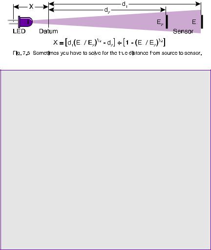
Lenses will distort the position of a point source. You can solve for the virtual origin of a source by measuring irradiance at two points and solving for the offset distance, X, using the Inverse Square Law:
E1(d1 + X)2 = E2(d2 + X)2
Figure 7.5 illustrates a typical setup to determine the location of an LED’s virtual point source (which is behind the LED due to the built-in lens). Two irradiance measurements at known distances from a reference point are all that is needed to calculate the offset to the virtual point source.
Units Conversion: Flux Density
IRRADIANCE:
1 W/cm2 (watts per square centimeter)
=104 W/m2 (watts per square meter)
=6.83 x 10⁶ lux at 555 nm
=14.33 gram*calories/cm2/minute
ILLUMINANCE:
1 lm/m2 (lumens per square meter)
=1 lux (lx)
=10-4 lm/cm2
=10-4 phot (ph)
=9.290 x 10⁻² lm/ft2
=9.290 x 10⁻² foot-candles (fc)
33

Radiance and Luminance:
Radiance is a measure of the flux density per unit solid viewing angle, expressed in W/cm2/sr. Radiance is independent of distance for an extended area source, because the sampled area increases with distance, cancelling inverse square losses.
The radiance, L, of a diffuse (Lambertian) surface is related to the radiant exitance (flux density), M, of a surface by the relationship:
L = M / π
Some luminance units (asb, L, fL) already contain π in the denominator, allowing simpler conversion to illuminance units.
Example: Suppose a diffuse surface with a reflectivity, ρ , of 85% is exposed to an illuminance, E, of 100.0 lux (lm/ m2) at the plane of the surface. What would be the luminance, L, of that surface, in cd/m2?
Solution:
1.) Calculate the luminous exitance of the surface: M = E * ρ
M = 100.0 * 0.85 = 85.0 lm/m2
2.) Calculate the luminance of the surface: L = M / π
L = 85.0 / π = 27.1 lm/m2/sr = 27.1 cd/m2
34

Irradiance From An Extended Source:
The irradiance, E, at any distance from a uniform extended area source, is related to the radiance, L, of the source by the following relationship, which depends only on the subtended central viewing angle, θ , of the radiance detector:
E = π L sin2(θ /2)
So, for an extended source with a radiance of 1 W/cm2/sr, and a detector with a viewing angle of 3° , the irradiance at any distance would be 2.15x 10⁻³ W/cm2. This assumes, of course, that the source extends beyond the viewing angle of the detector input optics.
Units Conversion: Radiance & Luminance
RADIANCE:
1 W/cm2/sr (watts per sq. cm per steradian)
=6.83 x 10⁶ lm/m2/sr at 555 nm
=683 cd/cm2 at 555 nm
LUMINANCE:
1 lm/m2/sr (lumens per sq. meter per steradian)
=1 candela/m2 (cd/m2)
=1 nit
=10-4 lm/cm2/sr
=10-4 cd/cm2
=10-4 stilb (sb)
=9.290 x 10⁻² cd/ft2
=9.290 x 10⁻² lm/ft2/sr
=π apostilbs (asb)
=π cd/π /m2
=π x 10-4 lamberts (L)
=π x 10-4 cd/π /cm2
=2.919 x 10⁻¹ foot-lamberts (fL)
=2.919 x 10⁻¹ lm/π /ft2/sr
35

Radiant and Luminous Intensity:
Radiant Intensity is a measure of radiometric power per unit solid angle, expressed in watts per steradian. Similarly, luminous intensity is a measure of visible power per solid angle, expressed in candela (lumens per steradian). Intensity is related to irradiance by the inverse square law, shown below in an alternate form:
I = E * d2
If you are wondering how the units cancel to get flux/sr from flux/area times distance squared, remember that steradians are a dimensionless quantity. Since the solid angle equals the area divided by the square of the radius, d2=A/Ω , and substitution yields:
I = E * A / Ω
The biggest source of confusion regarding intensity measurements involves the difference between Mean Spherical Candela and Beam Candela, both of which use the candela unit (lumens per steradian). Mean spherical measurements are made in an integrating sphere, and represent the total output in lumens divided by 4π sr in a sphere. Thus, a one candela isotropic lamp produces one lumen per steradian.
Beam candela, on the other hand, samples a very narrow angle and is only representative of the lumens per steradian at the peak intensity of the beam. This measurement is frequently misleading, since the sampling angle need not be defined.
36
Suppose that two LED’s each emit 0.1 lm total in a narrow beam: One has a 10° solid angle and the other a 5° angle. The 10° LED has an intensity of 4.2 cd, and the 5° LED an intensity of 16.7 cd. They both output the same total amount of light, however - 0.1 lm.
A flashlight with a million candela beam sounds very bright, but if its beam is only as wide as a laser beam, then it won’t be of much use. Be wary of specifications given in beam candela, because they often misrepresent the total output power of a lamp.
Units Conversion: Intensity
RADIANT INTENSITY:
1 W/sr (watts per steradian)
=12.566 watts (isotropic)
=4*π W
=683 candela at 555 nm
LUMINOUS INTENSITY:
1 lm/sr (lumens per steradian)
=1 candela (cd)
=4*π lumens (isotropic)
=1.464 x 10⁻³ watts/sr at 555 nm
37

Converting Between Geometries
Converting between geometry-based measurement units is difficult, and should only be attempted when it is impossible to measure in the actual desired units. You must be aware of what each of the measurement geometries implicitly assumes before you can convert. The example below shows the conversion between lux (lumens per square meter) and lumens.
Example: You measure 22.0 lux from a light bulb at a distance of 3.162 meters. How much light, in lumens, is the bulb producing? Assume that the clear enveloped lamp is an isotropic point source, with the exception that the base blocks a 30° solid angle.
Solution:
1.) Calculate the irradiance at 1.0 meter:
E1 = (d2 / d1)2 * E2
E1.0 m = (3.162 / 1.0)2 * 22.0 = 220 lm/m2
2.) Convert from lm/m2 to lm/sr at 1.0 m:
220 lm/m2 * 1 m2/sr = 220 lm/sr
3.) Calculate the solid angle of the lamp:
Ω = A / r2 = 2π h / r = 2π [1 - cos(α / 2)]
Ω = 2π [1 - cos(330 / 2)] = 12.35 sr
4.) Calculate the total lumen output:
220 lm/sr * 12.35 sr = 2717 lm
38
8Setting Up An Optical Bench
A Baffled Light Track
The best light measurement setup controls as many variables as possible. The idea is to prevent the measurement environment from influencing the measurement. Otherwise, the measurement will not be repeatable at a different time and place.
Baffles, for example, greatly reduce the influence of stray light reflections. A baffle is simply a sharp edged hole in a piece of thin sheet metal that has been painted black. Light outside of the optical beam is blocked and absorbed without affecting the optical path.
Multiple baffles are usually required in order to guarantee that light is trapped once it strikes a baffle. The best light trap of all, however, is empty space. It is a good idea to leave as much space between the optical path and walls or ceilings as is practical. Far away objects make weak reflective sources because of the Inverse Square Law. Objects that are near to the detector, however, have a significant effect, and should be painted with “black velvet” paint or moved out of view.
A shutter, door, or light trap in one of the baffles allows you to measure the background scatter component and subtract it from future readings. The “zero” reading should be made with the source ON, to maintain the operating temperature of the lamp as well as measure light that has defeated your baffling scheme.
39
Kinematic Mounts
Accurate distance measurements and repeatable positioning in the optical path are the most important considerations when setting up an optical bench. The goal of an optical bench is to provide repeatability. It is not enough to merely control the distance to the source, since many sources have non-uniform beams. A proper detector mounting system provides for adjustment of position and angle in 3-D space, as well as interchangeability into a calibrated position in the optical path.
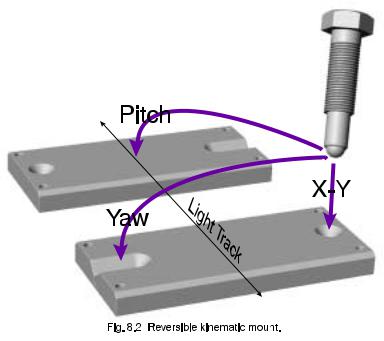
To make a kinematic fixture, cut a cone and a conical slot into a piece of metal using a 45° conical end mill (see fig. 8.2). A kinematic mount is a three point fixture, with the third point being any planar face. The three mounting points can be large bolts that have been machined into a ball on one end, or commercially available 1/4-80 screws with ball bearing tips (from Thorlabs, Inc.) for small fixtures.
The first leg rests in the cone hole, fixing the position of that leg as an X-Y point. The ball tip ensures that it makes reliable, repeatable contact with the cone surface. The second leg sits in
the conical slot, fixed only in Yaw, or angle in the horizontal plane.
The use of a slot prevents the Yaw leg from competing with the X-Y leg for control. The third leg rests on any flat horizontal surface, fixing the Pitch, or forward tilt, of the assembly.
A three legged detector carrier sitting on a kinematic mounting plate is the most accurate way to interchange detectors into the optical path, allowing intercomparisons between two or more detectors.
40