

Schmidt G.Beginners introduction to the assembly language of Atmel AVR microprocessors.2004
.pdfBeginners Introduction to the Assembly Language of ATMELAVRMicroprocessors
by
Gerhard Schmidt
http://www.avrasmtutorial.net
October 2004

Avr-Asm-Tutorial 1 http://www.avr-asm-tutorial.net
Content
Why learning Assembler?.......................................................................................................................... |
1 |
Short and easy....................................................................................................................................... |
1 |
Fast and quick........................................................................................................................................ |
1 |
Assembler is easy to learn..................................................................................................................... |
1 |
AT90Sxxxx are ideal for learning assembler........................................................................................ |
1 |
Test it!.................................................................................................................................................... |
1 |
Hardware for AVRAssemblerProgramming........................................................................................... |
2 |
The ISPInterface of the AVRprocessor family................................................................................... |
2 |
Programmer for the PCParallelPort.................................................................................................... |
2 |
Experimental board with a AT90S2313................................................................................................ |
3 |
Readytouse commercial programming boards for the AVRfamily................................................... |
4 |
Tools for AVR assembly programing........................................................................................................ |
5 |
The editor.............................................................................................................................................. |
5 |
The assembler........................................................................................................................................ |
6 |
Programming the chips.......................................................................................................................... |
7 |
Simulation in the studio......................................................................................................................... |
7 |
Register...................................................................................................................................................... |
9 |
What is a register?................................................................................................................................. |
9 |
Different registers................................................................................................................................ |
10 |
Pointerregister.................................................................................................................................... |
10 |
Recommendation for the use of registers............................................................................................ |
11 |
Ports......................................................................................................................................................... |
12 |
What is a Port?.................................................................................................................................... |
12 |
Details of relevant ports in the AVR................................................................................................... |
13 |
The status register as the most used port............................................................................................. |
13 |
Port details........................................................................................................................................... |
14 |
SRAM.................................................................................................................................................. |
15 |
Using SRAM in AVR assembler language......................................................................................... |
15 |
What is SRAM?................................................................................................................................... |
15 |
For what purposes can I use SRAM?.................................................................................................. |
15 |
How to use SRAM?............................................................................................................................. |
15 |
Use of SRAM as stack......................................................................................................................... |
16 |
Defining SRAM as stack................................................................................................................ |
16 |
Use of the stack............................................................................................................................... |
17 |
Bugs with the stack operation......................................................................................................... |
17 |
Jumping and Branching............................................................................................................................ |
19 |
Controlling sequential execution of the program................................................................................ |
19 |
What happens during a reset?......................................................................................................... |
19 |
Linear program execution and branches.............................................................................................. |
20 |
Timing during program execution....................................................................................................... |
20 |
Macros and program execution........................................................................................................... |
21 |
Subroutines.......................................................................................................................................... |
21 |
Interrupts and program execution........................................................................................................ |
23 |
Calculations.............................................................................................................................................. |
25 |
Number systems in assembler............................................................................................................. |
25 |
Positive whole numbers (bytes, words, etc.).................................................................................. |
25 |
Signed numbers (integers).............................................................................................................. |
25 |
Binary Coded Digits, BCD............................................................................................................. |
25 |
Packed BCDs.................................................................................................................................. |
26 |
Numbers in ASCIIformat.............................................................................................................. |
26 |
Bit manipulations................................................................................................................................ |
26 |
Shift and rotate.................................................................................................................................... |
27 |
Adding, subtracting and comparing.................................................................................................... |
28 |
Format conversion for numbers........................................................................................................... |
29 |
Multiplication...................................................................................................................................... |
30 |
Decimal multiplication................................................................................................................... |
30 |
Binary multiplication...................................................................................................................... |
30 |
Avr-Asm-Tutorial |
2 |
http://www.avr-asm-tutorial.net |
|
|
|
AVRAssembler program............................................................................................................... |
|
31 |
Binary rotation................................................................................................................................ |
|
32 |
Multiplication in the studio............................................................................................................. |
|
32 |
Division............................................................................................................................................... |
|
34 |
Decimal division............................................................................................................................. |
|
34 |
Binary division............................................................................................................................... |
|
34 |
Program steps during division........................................................................................................ |
|
35 |
Division in the simulator................................................................................................................ |
|
35 |
Number conversion............................................................................................................................. |
|
37 |
Decimal Fractions................................................................................................................................ |
|
37 |
Linear conversions.......................................................................................................................... |
|
37 |
Example 1: 8bitADconverter with fixed decimal output............................................................ |
38 |
|
Example 2: 10bitADconverter with fixed decimal output.......................................................... |
40 |
|
Annex....................................................................................................................................................... |
|
41 |
Commands sorted by function............................................................................................................. |
|
41 |
Command list in alphabetic order....................................................................................................... |
|
43 |
Assembler directives....................................................................................................................... |
|
43 |
Commands...................................................................................................................................... |
|
43 |
Port details........................................................................................................................................... |
|
45 |
StatusRegister, Accumulator flags................................................................................................ |
|
45 |
Stackpointer.................................................................................................................................... |
|
45 |
SRAM and External Interrupt control............................................................................................ |
|
45 |
External Interrupt Control............................................................................................................... |
|
46 |
Timer Interrupt Control.................................................................................................................. |
|
46 |
Timer/Counter 0.............................................................................................................................. |
|
47 |
Timer/Counter 1.............................................................................................................................. |
|
48 |
WatchdogTimer............................................................................................................................. |
|
49 |
EEPROM........................................................................................................................................ |
|
49 |
Serial Peripheral Interface SPI........................................................................................................ |
|
50 |
UART............................................................................................................................................. |
|
51 |
Analog Comparator........................................................................................................................ |
|
51 |
I/O Ports.......................................................................................................................................... |
|
52 |
Ports, alphabetic order......................................................................................................................... |
|
52 |
List of abbreviations............................................................................................................................ |
|
53 |
Errors in previous versions.................................................................................................................. |
|
54 |
Avr-Asm-Tutorial |
1 |
http://www.avr-asm-tutorial.net |
|
|
|
Why learning Assembler?
Assembler or other languages, that is the question. Why should I learn another language, if I already learned other programming languages? The best argument: while you live in France you are able to get through by speaking english, but you will never feel at home then, and life remains complicated. You can get through with this, but it is rather inappropriate. If things need a hurry, you should use the country's language.
Short and easy
Assembler commands translate one by one to executed machine commands. The processor needs only to execute what you want it to do and what is necessary to perform the task. No extra loops and unnecessary features blow up the generated code. If your program storage is short and limited and you have to optimize your program to fit into memory, assembler is choice 1. Shorter programs are easier to debug, every step makes sense.
Fast and quick
Because only necessary code steps are executed, assembly programs are as fast as possible. The duration of every step is known. Time critical applications, like time measurements without a hardware timer, that should perform excellent, must be written in assembler. If you have more time and don't mind if your chip remains 99% in a wait state type of operation, you can choose any language you want.
Assembler is easy to learn
It is not true that assmbly language is more complicated or not as easy to understand than other languages. Learning assembly language for whatever hardware type brings you to understand the basic concepts of any other assembly language dialect. Adding other dialects later is easy. The first assembly code does not look very attractive, with every 100 additional lines programmed it looks better. Perfect programs require some thousand lines of code of exercise, and optimization requires lots of work. As some features are hardware-dependant optimal code requires some familiarity with the hardware concept and the dialect. The first steps are hard in any language. After some weeks of programming you will laugh if you go through your first code. Some assembler commands need some monthes of experience.
AT90Sxxxx are ideal for learning assembler
Assembler programs are a little bit silly: the chip executes anything you tell it to do, and does not ask you if you are sure overwriting this and that. All protections must be programmed by you, the chip does anything like it is told. No window warns you, unless you programmed it before.
Basic design errors are as complicated to debug like in any other computer language. But: testing programs on ATMEL chips is very easy. If it does not do what you expect it to do, you can easily add some diagnostic lines to the code, reprogram the chip and test it. Bye, bye to you EPROM programmers, to the UV lamps used to erase your test program, to you pins that don't fit into the socket after having them removed some douzend times.
Changes are now programmed fast, compiled in no time, and either simulated in the studio or checked incircuit. No pin is removed, and no UV lamp gives up just in the moment when you had your excellent idea about that bug.
Test it!
Be patient doing your first steps! If you are familiar with another (high-level) language: forget it for the first time. Behind every assembler language there is a certain hardware concept. Most of the special features of other computer languages don't make any sense in assembler.
The first five commands are not easy to learn, then your learning speed rises fast. After you had your first lines: grab the instruction set list and lay back in the bathtub, wondering what all the other commands are like.
Don't try to program a mega-machine to start with. This does not make sense in any computer language, and just produces frustration.
Comment your subroutines and store them in a special directory, if debugged: you will need them again in a short time.
Have success!
Avr-Asm-Tutorial |
2 |
http://www.avr-asm-tutorial.net |
|
|
|
Hardware for AVRAssemblerProgramming
Learning assembler requires some simple hardware equipment to test your programs, and see if it works in practice.
This section shows two easy schematics that enable you to homebrew the required hardware and gives you the necessary hints on the required background. This hardware really is easy to build. I know nothing easier than that to test your first software steps. If you like to make more experiments, leave some more space for future extensions on your experimental board.
If you don't like the smell of soldering, you can buy a ready-to-use board, too. The available boards are characterised in this section below.
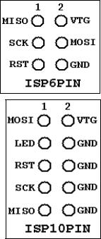
The ISPInterface of the AVRprocessor family
Before going into practice, we have to learn a few essentials on the serial programming mode of the AVR family. No, you don't need three different voltages to program and read an AVR flash memory. No, you don't need another microprocessor to program the AVRs. No, you don't need 10 I/O lines to tell the chip what you like it to do. And you don't even have to remove the AVR from your experimental board, before programming it. It's even easier than that.
All this is done by a build-in interface in the AVR chip, that enables you to write and read the content of the program flash and the built-in-EEPROM. This interface works serially and needs three signal lines:
•SCK: A clock signal that shifts the bits to be written to the memory into an internal shift register, and that shifts out the bits to be read from another internal shift register,
•MOSI: The data signal that sends the bits to be written to the AVR,
•MISO: The data signal that receives the bits read from the AVR.
These three signal pins are internally connected to the programming machine only if you change the RESET (sometimes also called RST or restart) pin to zero. Otherwise, during normal operation of the AVR, these pins are programmable I/O lines like all the others.
If you like to use these pins for other purposes during normal operation, and for in- system-programming, you'll have to take care, that these two purposes do not conflict. Usually you then decouple these by resistors or by use of a multiplexer. What is necessary in your case, depends from your use of the pins in the normal operation mode. You're lucky, if you can use them for in- system-programming exclusively.
Not necessary, but recommendable for in-system-programming is, that you supply the programming hardware out of the supply voltage of your system. That makes it easy, and requires two additional lines between the programmer and the AVR board. GND is the common ground, VTG (target voltage) the supply voltage (usually 5.0 volts). This adds up to 6 lines between the programmer and the AVR board. The resulting ISP6 connection is, as defined by AMEL, is shown on the left.
Standards always have alternative standards, that were used earlier. This is the technical basis that constitutes the adaptor industry. In our case the alternative standard was designed as ISP10 and was used on the STK200 board. It's still a very widespread standard, and even the STK500 is still equipped with it. ISP10 has an additional signal to drive a red LED. This LED signals that the programmer is doing his job. A good idea. Just connect the LED to a resistor and clamp it the positive supply voltage.
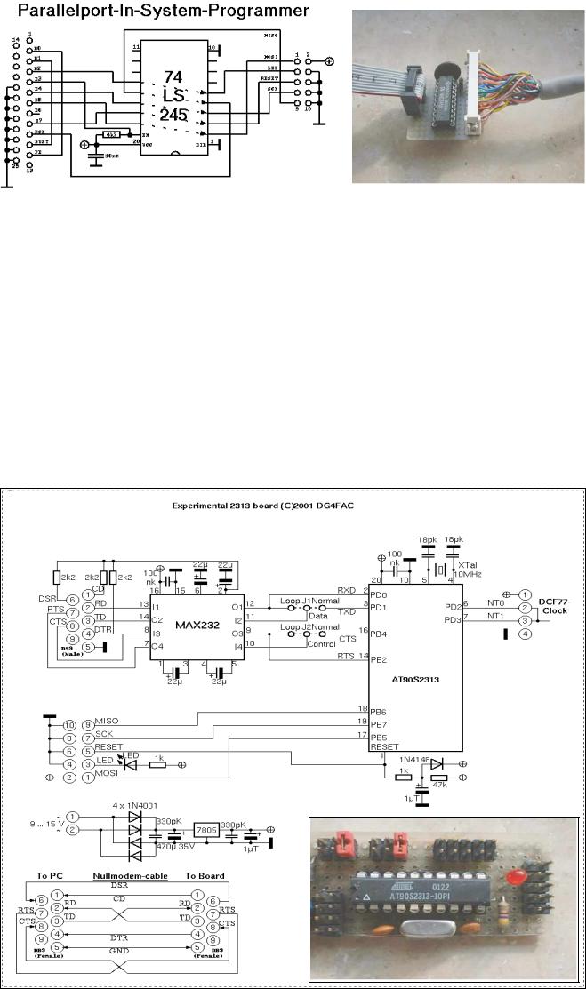
Programmer for the PCParallelPort
Now, heat up your soldering iron and build up your programmer. It is a quite easy schematic and works with standard parts from your well-sorted experiments box.
Yes, that's all you need to program an AVR. The 25-pin plug goes into the parallel port of your PC, the 10- pin-ISP goes to your AVR experimental board. If your box doesn't have a 74LS245, you can also use a 74HC245 or a 74LS244/74HC244 (by changing some pins and signals). If you use HC, don't forget to tie unused inputs either to GND or the supply voltage, otherwise the buffers might produce extra noise by capacitive switching.
Avr-Asm-Tutorial |
3 |
|
http://www.avr-asm-tutorial.net |
|
|
|
|
|
|
|
|
|
|
|
|
|
|
|
|
|
|
|
|
|
|
|
|
|
|
The necessary program algorithm is done by the ISP software, that is available from ATMEL's software download page.
Experimental board with a AT90S2313
For test purposes we use a AT90S2313 on an experimental board. The schematic shows
•a small voltage supply for connection to an AC transformer and a voltage regulator 5V/1A,
•a XTAL clock generator (here with a 10 Mcs/s, all other frequencies below the maximum for the 2313 will also work),
•the necessary parts for a safe reset during supply voltage switching,
•the ISP-Programming-Interface (here with a ISP10PIN-connector).
So that's what you need to start with. Connect other peripheral add-ons to the numerous free I/O pins of the 2313.
The easiest output device can be a LED, connected via a resistor to the positive supply voltage. With that, you can start writing your first assembler program switching the LED on and off.
Avr-Asm-Tutorial |
4 |
http://www.avr-asm-tutorial.net |
|
|
|
Readytouse commercial programming boards for the AVRfamily
If you do not like homebrewed hardware, and if have some extra money left that you don't know what to do with, you can buy a commercial programming board. Easy to get is the STK500 (e.g. from ATMEL. It has the following hardware:
•Sockets for programming most of the AVR types,
•serial und parallel programming,
•ISP6PINand ISP10PIN-connector for external In-System-Programming,
•programmable oscillator frequency and suplly voltages,
•plug-in switches and LEDs,
•a plugged RS232C-connector (UART),
•a serial Flash-EEPROM,
•access to all ports via a 10-pin connector.
Experiments can start with the also supplied AT90S8515. The board is connected to the PC using a serial port (COMx) and is controlled by later versions of AVR studio, available from ATMEL's webpage. This covers all hardware requirements that the beginner might have.
Avr-Asm-Tutorial |
5 |
http://www.avr-asm-tutorial.net |
|
|
|
Tools for AVR assembly programing
This section provides informations about the necessary tools that are used to program AVRs with the STK200 board. Programming with the STK500 is very different and shown in more detail in the Studio section. Note that the older software for the STK200 is not supported any more.
Four basic programs are necessary for assembly programming. These tools are:
•the editor,
•the assembler program,
•the chip programing interface, and
•the simulator.
The necessary software tools are ©ATMEL and available on the webpage of ATMEL for download. The screenshots here are ©ATMEL. It should be mentioned that there are different versions of the software and some of the screenshots are subject to change with the used version. Some windows or menues look different in different versions. The basic functions are mainly unchanged. Refer to the programer's handbook, this page just provides an overview for the beginner's first steps and is not written for the assembly programing expert.
The editor
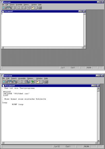
Assembler programs are written with a editor. The editor just has to be able to create and edit ASCII text files. So, basically, any simple editor does it. I recommend the use of a more advanced editor, either WAVRASM©ATMEL or the editor written by Tan Silliksaar (screenshot see below).
An assembly program written with WAVRASM© goes like this. Just install WAVRASM© and start the program:
Now we type in our directives and assembly commands in the WAVRASM editor window, together with some comments (starting with ;). That should look like this:
Now store the program text, named to something.asm into a dedicated directory, using the file menue. The assembly program is complete now.
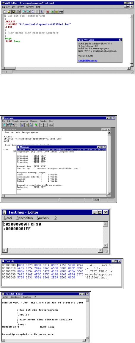
If you like editing a little more in a sophisticated manner you can use the excellent editor written by Tan Silliksaar. This editor tools is designed for AVRs and available for free from Tan's webpage. In this editor our program looks like this:
Avr-Asm-Tutorial |
6 |
http://www.avr-asm-tutorial.net |
|
|
|
The editor recognizes commands automatically and uses different colors (syntax highlighting) to signal user constants and typing errors in those commands (in black). Storing the code in an .asm file provides nearly the same text file.
The assembler
Now we have to translate this code to a machine-oriented form well understood by the AVR chip. Doing this is called assembling, which means collecting the right command words. If you use WAVRASM© just click assemble on the menue. The result is shown here:
The assembler reports the complete translation with no errors. If errors occur these are notified. Assembling resulted in one word of code which resulted from the command we used. Assembling our single asm-text file now has produced four other files (not all apply here).
The first of these four new files, TEST.EEP, holds the content that should be written to the EEPROM of the AVR. This is not very interesting in our case, because we didn't program any content for the EEPROM. The assembler has therefore deleted this file when he completed the assembly run.
The second file, TEST.HEX, is more relevant because this file holds the commands later programmed into the AVR chip. This file looks like this.
The hex numbers are written in a special ASCII form, together with adress informations and a checksum for each line. This form is called Intel-hex-format, and it is very old. The form is well understood by the programing
software.
The third file, TEST.OBJ, will be introduced later, this file is needed to simulate an AVR. Its format is hexadecimal and defined by ATMEL. Using a hex-editor its content looks like this. Attention: This file format is
not compatible with the programer software, don't use this file to program the AVR (a very common error when starting).
The fourth file, TEST.LST, is a text file. Display its content with a simple editor. The following results.
The program with all its adresses, comands and error messages are displayed in a readable form. You will need that file in some cases to debug errors.