

MAX6734AKA
.pdf19-0605; Rev 0; 8/06
Single-/Dual-/Triple-Voltage µP Supervisory Circuits with Independent Watchdog Output
General Description
The MAX6730A–MAX6735A single-/dual-/triple-voltage microprocessor (µP) supervisors feature a watchdog timer and manual reset capability. The MAX6730A– MAX6735A offer factory-set reset thresholds for monitoring voltages from +0.9V to +5V and an adjustable reset input for monitoring voltages down to +0.63V. The combination of these features significantly improves system reliability and accuracy when compared to separate ICs or discrete components.
The active-low reset output asserts and remains asserted for the reset timeout period after all the monitored voltages exceed their respective thresholds. Multiple factoryset reset threshold combinations reduce the number of external components required. The MAX6730A/ MAX6731A monitor a single fixed voltage, the MAX6732A/ MAX6733A monitor two fixed voltages, and the MAX6734A/MAX6735A monitor two fixed voltages and one adjustable voltage. All devices are offered with six minimum reset timeout periods ranging from 1.1ms to 1120ms.
The MAX6730A–MAX6735A feature a watchdog timer with an independent watchdog output. The watchdog timer prevents system lockup during code execution errors. A watchdog startup delay of 54s after reset asserts allows system initialization during power-up. The watchdog operates in normal mode with a 1.68s delay after initialization. The MAX6730A/MAX6732A/ MAX6734A provide an active-low, open-drain watchdog output. The MAX6731A/MAX6733A/MAX6735A provide an active-low, push-pull watchdog output.
Other features include a manual reset input (MAX6730A/ MAX6731A/MAX6734A/MAX6735A) and push-pull reset output (MAX6731A/MAX6733A/MAX6735A) or opendrain reset output (MAX6730A/MAX6732A/MAX6734A). The MAX6730A–MAX6733A are offered in a tiny 6-pin SOT23 package. The MAX6734A/MAX6735A are offered in an 8-pin, space-saving SOT23 package. All devices are fully specified over the extended -40°C to +125°C temperature range.
Applications
Multivoltage Systems
Telecom/Networking Equipment
Computers/Servers
Portable/Battery-Operated Equipment
Industrial Equipment
Printer/Fax
Set-Top Boxes
Typical Operating Circuit and Pin Configurations appear at end of data sheet.
Features
♦VCC1 (Primary Supply) Reset Threshold Voltages from +1.575V to +4.63V
♦VCC2 (Secondary Supply) Reset Threshold Voltages from +0.79V to +3.08V
♦Adjustable RSTIN Threshold for Monitoring Voltages Down to +0.63V (MAX6734A/MAX6735A Only)
♦Six Reset Timeout Options
♦Watchdog Timer with Independent Watchdog Output 35s (min) Initial Watchdog Startup Period
1.12s (min) Normal Watchdog Timeout Period
♦Manual Reset Input (MAX6730A/MAX6731A/ MAX6734A/MAX6735A)
♦Guaranteed Reset Valid down to VCC1 or VCC2 = +0.8V
♦Push-Pull RESET or Open-Drain RESET Output
♦Immune to Short VCC Transients
♦Low Supply Current: 14µA (typ) at +3.6V
♦Small 6-Pin and 8-Pin SOT23 Packages
Ordering Information
PART* |
PIN-PACKAGE |
PKG CODE |
|
|
|
MAX6730AUT_D_ -T |
6 SOT23-6 |
U6-1 |
|
|
|
MAX6731AUT_D_ -T |
6 SOT23-6 |
U6-1 |
|
|
|
MAX6732AUT_ _D_ -T |
6 SOT23-6 |
U6-1 |
|
|
|
MAX6733AUT_ _D_ -T |
6 SOT23-6 |
U6-1 |
MAX6734AKA_ _D_ -T |
8 SOT23-8 |
K8S-3 |
MAX6735AKA_ _D_ -T |
8 SOT23-8 |
K8S-3 |
|
|
|
All devices specified over the -40°C to +125°C operating temperature range.
*Note: Insert the threshold level suffixes for VCC1 and VCC2 (Table 1) after “UT” or “KA.” For the MAX6730A/MAX6731A, insert only the VCC1 threshold suffix after the “UT.” Insert the reset timeout delay (Table 2) after “D” to complete the part number. For example, the MAX6732AUTLTD3-T provides a VCC1 threshold of +4.625V, a VCC2 threshold of +3.075V, and a 210ms reset timeout period. Sample stock is generally held on standard versions only (see the Standard Versions table). Standard versions have an order increment requirement of 2500 pieces. Nonstandard versions have an order increment requirement of 10,000 pieces. Contact factory for availability.
Devices are available in both leaded and lead-free packaging. Specify lead-free by replacing “T” with “+T” when ordering.
________________________________________________________________ Maxim Integrated Products 1
For pricing, delivery, and ordering information, please contact Maxim/Dallas Direct! at 1-888-629-4642, or visit Maxim’s website at www.maxim-ic.com.
MAX6735A–MAX6730A

MAX6730A–MAX6735A
Single-/Dual-/Triple-Voltage µP Supervisory Circuits with Independent Watchdog Output
ABSOLUTE MAXIMUM RATINGS
VCC1, VCC2, RSTIN, MR, WDI to GND |
..................... |
-0.3V to +6V |
RST, WDO to GND (open drain)............................... |
|
-0.3V to +6V |
RST, WDO to GND (push-pull) ................. |
- 0.3V to (VCC1 + 0.3V) |
|
Input Current/Output Current (all pins) ............................... |
|
20mA |
Continuous Power Dissipation (TA = +70°C) |
|
|
6-Pin SOT23-6 (derate 8.7mW/°C above ........+70°C) |
696mW |
|
8-Pin SOT23-8 (derate 8.9mW/°C above ........+70°C) |
714mW |
|
Operating Temperature Range ......................... |
-40°C to +125°C |
Storage Temperature Range ............................. |
-65°C to +150°C |
Junction Temperature ...................................................... |
+150°C |
Lead Temperature (soldering, 10s) ................................. |
+300°C |
Stresses beyond those listed under “Absolute Maximum Ratings” may cause permanent damage to the device. These are stress ratings only, and functional operation of the device at these or any other conditions beyond those indicated in the operational sections of the specifications is not implied. Exposure to absolute maximum rating conditions for extended periods may affect device reliability.
ELECTRICAL CHARACTERISTICS
(VCC1 = VCC2 = +0.8V to +5.5V, TA = -40°C to +125°C, unless otherwise noted. Typical values are at TA = +25°C.) (Note 1)
PARAMETER |
SYMBOL |
CONDITIONS |
MIN |
TYP |
MAX |
UNITS |
|
|
|
|
|
|
|
Supply Voltage |
VCC1, |
|
0.8 |
|
5.5 |
V |
VCC2 |
|
|
||||
|
|
|
|
|
|
|
|
|
VCC1 < +5.5V, all I/O connections |
|
15 |
39 |
|
|
|
open, outputs not asserted |
|
|
||
|
ICC1 |
|
|
|
|
|
|
|
|
|
|
|
|
|
VCC1 < +3.6V, all I/O connections |
|
10 |
28 |
|
|
|
|
|
|
|||
|
|
open, outputs not asserted |
|
|
||
Supply Current |
|
|
|
|
µA |
|
|
|
|
|
|
||
|
VCC2 < +3.6V, all I/O connections |
|
4 |
11 |
||
|
|
|
|
|||
|
|
open, outputs not asserted |
|
|
||
|
ICC2 |
|
|
|
|
|
|
|
|
|
|
|
|
|
VCC2 < +2.75V, all I/O connections |
|
3 |
9 |
|
|
|
|
|
|
|||
|
|
open, outputs not asserted |
|
|
||
|
|
|
|
|
|
|
|
|
|
|
|
|
|
|
|
L (falling) |
4.500 |
4.625 |
4.750 |
|
|
|
|
|
|
|
|
|
|
M (falling) |
4.250 |
4.375 |
4.500 |
|
|
|
|
|
|
|
|
|
|
T (falling) |
3.000 |
3.075 |
3.150 |
|
|
|
|
|
|
|
|
|
|
S (falling) |
2.850 |
2.925 |
3.000 |
|
|
|
|
|
|
|
|
VCC1 Reset Threshold |
VTH1 |
R (falling) |
2.550 |
2.625 |
2.700 |
V |
|
|
Z (falling) |
2.250 |
2.313 |
2.375 |
|
|
|
Y (falling) |
2.125 |
2.188 |
2.250 |
|
|
|
W (falling) |
1.620 |
1.665 |
1.710 |
|
|
|
|
|
|
|
|
|
|
V (falling) |
1.530 |
1.575 |
1.620 |
|
|
|
|
|
|
|
|
2 _______________________________________________________________________________________ 


Single-/Dual-/Triple-Voltage µP Supervisory Circuits with Independent Watchdog Output
ELECTRICAL CHARACTERISTICS (continued)
(VCC1 = VCC2 = +0.8V to +5.5V, TA = -40°C to +125°C, unless otherwise noted. Typical values are at TA = +25°C.) (Note 1)
PARAMETER |
SYMBOL |
CONDITIONS |
MIN |
TYP |
MAX |
UNITS |
|
|
|
T (falling) |
3.000 |
3.075 |
3.150 |
|
|
|
|
|
|
|
|
|
|
|
|
S (falling) |
2.850 |
2.925 |
3.000 |
|
|
|
|
|
|
|
|
|
|
|
|
R (falling) |
2.550 |
2.625 |
2.700 |
|
|
|
|
|
|
|
|
|
|
|
|
Z (falling) |
2.250 |
2.313 |
2.375 |
|
|
|
|
|
|
|
|
|
|
|
|
Y (falling) |
2.125 |
2.188 |
2.250 |
|
|
|
|
W (falling) |
1.620 |
1.665 |
1.710 |
|
|
|
|
|
|
|
|
|
|
VCC2 Reset Threshold |
VTH2 |
V (falling) |
1.530 |
1.575 |
1.620 |
V |
|
|
|
I (falling) |
1.350 |
1.388 |
1.425 |
|
|
|
|
|
|
|
|
|
|
|
|
H (falling) |
1.275 |
1.313 |
1.350 |
|
|
|
|
|
|
|
|
|
|
|
|
G (falling) |
1.080 |
1.110 |
1.140 |
|
|
|
|
|
|
|
|
|
|
|
|
F (falling) |
1.020 |
1.050 |
1.080 |
|
|
|
|
E (falling) |
0.810 |
0.833 |
0.855 |
|
|
|
|
D (falling) |
0.765 |
0.788 |
0.810 |
|
|
Reset Threshold Tempco |
|
|
|
20 |
|
ppm/oC |
|
Reset Threshold Hysteresis |
VHYST |
Referenced to VTH typical |
|
0.5 |
|
% |
|
|
|
VCC1 = (VTH1 + 100mV) to |
|
|
|
|
|
VCC_ to RST Output Delay |
tRD |
(VTH1 - 100mV) or |
|
45 |
|
µs |
|
VCC2 = (VTH2 + 75mV) to |
|
|
|||||
|
|
|
|
|
|
||
|
|
(VTH2 - 75mV) |
|
|
|
|
|
|
|
D1 |
1.1 |
1.65 |
2.2 |
|
|
|
|
|
|
|
|
|
|
|
|
D2 |
8.8 |
13.2 |
17.6 |
|
|
|
|
|
|
|
|
|
|
Reset Timeout Period |
tRP |
D3 |
140 |
210 |
280 |
ms |
|
|
|
|
|
||||
D5 |
280 |
420 |
560 |
||||
|
|
|
|||||
|
|
|
|
|
|
|
|
|
|
D6 |
560 |
840 |
1120 |
|
|
|
|
|
|
|
|
|
|
|
|
D4 |
1120 |
1680 |
2240 |
|
|
|
|
|
|
|
|
|
|
ADJUSTABLE RESET COMPARATOR INPUT (MAX6734A/MAX6735A) |
|
|
|
|
|||
|
|
|
|
|
|
|
|
RSTIN Input Threshold |
VRSTIN |
|
611 |
626.5 |
642 |
mV |
|
RSTIN Input Current |
IRSTIN |
|
-100 |
|
+100 |
nA |
|
RSTIN Hysteresis |
|
|
|
3 |
|
mV |
|
|
|
|
|
|
|
|
|
RSTIN to Reset Output Delay |
tRSTIND |
VRSTIN to (VRSTIN - 30mV) |
|
22 |
|
µs |
|
MANUAL RESET INPUT (MAX6730A/MAX6731A/MAX6734A/MAX6735A) |
|
|
|
|
|||
MR Input Threshold |
VIL |
|
|
|
0.3 × VCC1 |
V |
|
VIH |
|
0.7 × VCC1 |
|
|
|||
|
|
|
|
|
|||
MR Minimum Pulse Width |
|
|
1 |
|
|
µs |
|
|
|
|
|
|
|
|
|
MR Glitch Rejection |
|
|
|
100 |
|
ns |
|
MR to Reset Output Delay |
tMR |
|
|
200 |
|
ns |
|
MR Pullup Resistance |
|
|
25 |
50 |
80 |
kΩ |
|
MAX6735A–MAX6730A
_______________________________________________________________________________________ 3

MAX6730A–MAX6735A
Single-/Dual-/Triple-Voltage µP Supervisory Circuits with Independent Watchdog Output
ELECTRICAL CHARACTERISTICS (continued)
(VCC1 = VCC2 = +0.8V to +5.5V, TA = -40°C to +125°C, unless otherwise noted. Typical values are at TA = +25°C.) (Note 1)
PARAMETER |
SYMBOL |
CONDITIONS |
MIN |
TYP |
MAX |
UNITS |
|
WATCHDOG INPUT |
|
|
|
|
|
|
|
|
|
|
|
|
|
|
|
|
tWD-L |
First watchdog period after reset |
|
35 |
54 |
72 |
|
Watchdog Timeout Period |
timeout period |
|
s |
||||
|
|
|
|
|
|||
|
|
|
|
|
|
|
|
|
tWD-S |
Normal mode |
1.12 |
1.68 |
2.24 |
|
|
WDI Pulse Width |
tWDI |
(Note 2) |
|
50 |
|
|
ns |
WDI Input Voltage |
VIL |
|
|
|
|
0.3 × VCC1 |
V |
VIH |
|
0.7 × VCC1 |
|
|
|||
|
|
|
|
|
|||
WDI Input Current |
IWDI |
WDI = 0V or VCC1 |
|
-1 |
|
+1 |
µA |
RESET/WATCHDOG OUTPUT |
|
|
|
|
|
|
|
|
|
VCC1 or VCC2 ≥ +0.8V, |
|
|
|
0.3 |
|
|
|
ISINK = 1µA, output asserted |
|
|
|
|
|
|
|
|
|
|
|
|
|
|
|
VCC1 or VCC2 ≥ +1.0V, |
|
|
|
0.3 |
|
|
|
ISINK = 50µA, output asserted |
|
|
|
|
|
|
|
|
|
|
|
|
|
RST/ WDO Output Low Voltage |
VOL |
VCC1 or VCC2 ≥ +1.2V, |
|
|
|
0.3 |
V |
(Push-Pull or Open Drain) |
ISINK = 100µA, output asserted |
|
|
|
|||
|
|
|
|
|
|
||
|
|
VCC1 or VCC2 ≥ +2.7V, |
|
|
|
0.3 |
|
|
|
ISINK = 1.2mA, output asserted |
|
|
|
|
|
|
|
|
|
|
|
|
|
|
|
VCC1 or VCC2 ≥ +4.5V, |
|
|
|
0.4 |
|
|
|
ISINK = 3.2mA, output asserted |
|
|
|
|
|
|
|
|
|
|
|
|
|
|
|
VCC1 ≥ +1.8V, ISOURCE = 200µA, |
0.8 |
× VCC1 |
|
|
|
|
|
output not asserted |
|
|
|
||
|
|
|
|
|
|
|
|
|
|
|
|
|
|
|
|
RST/ WDO Output High Voltage |
VOH |
VCC1 ≥ +2.7V, ISOURCE = 500µA, |
0.8 |
× VCC1 |
|
|
V |
(Push-Pull Only) |
output not asserted |
|
|
||||
|
|
|
|
|
|
||
|
|
|
|
|
|
|
|
|
|
VCC1 ≥ +4.5V, ISOURCE = 800µA, |
0.8 |
× VCC1 |
|
|
|
|
|
output not asserted |
|
|
|
||
|
|
|
|
|
|
|
|
|
|
|
|
|
|
|
|
RST/ WDO Output Open-Drain |
|
Output not asserted |
|
|
|
0.5 |
µA |
Leakage Current |
|
|
|
|
|||
|
|
|
|
|
|
|
|
|
|
|
|
|
|
|
|
Note 1: Devices tested at TA = +25°C. Overtemperature limits are guaranteed by design and not production tested. Note 2: Parameter guaranteed by design.
4 _______________________________________________________________________________________

Single-/Dual-/Triple-Voltage µP Supervisory Circuits with Independent Watchdog Output
Typical Operating Characteristics
(VCC1 = +5V, VCC2 = +3.3V, TA = +25°C, unless otherwise noted.)
SUPPLY CURRENT vs. TEMPERATURE |
SUPPLY CURRENT vs. TEMPERATURE |
SUPPLY CURRENT vs. TEMPERATURE |
(VCC1 = +5V, VCC2 = +3.3V) |
(VCC1 = +3.3V, VCC2 = +2.5V) |
(VCC1 = +2.5V, VCC2 = +1.8V) |
SUPPLY CURRENT ( A)
20 |
TOTAL |
toc01 |
|
18 |
|||
-35A |
|||
|
|||
16 |
|
MAX6730A |
|
|
|
||
14 |
ICC1 |
|
|
|
|
12
10
8
6
4 |
|
ICC2 |
|
2
0
-40 -25 -10 5 20 35 50 65 80 95 110 125 TEMPERATURE (°C)
SUPPLY CURRENT ( A)
20 |
|
|
|
-35A toc02 |
|
18 |
|
|
|
A)( |
|
14 |
|
|
|
MAX6730A |
|
16 |
|
TOTAL |
|
|
|
|
|
|
|
CURRENT |
|
12 |
|
|
|
|
|
|
|
|
|
|
|
10 |
|
ICC1 |
|
|
SUPPLY |
6 |
|
|
|
|
|
8 |
|
|
|
|
|
4 |
|
ICC2 |
|
|
|
2 |
|
|
|
|
|
|
|
|
|
|
|
0 |
|
|
|
|
|
-40 -25 -10 |
5 |
20 35 50 65 80 |
95 |
110 125 |
|
|
|
TEMPERATURE (°C) |
|
|
|
20
18
16
14
12
10
8
6
4
2
0
MAX6730A-35A toc03
TOTAL |
ICC1
ICC2
-40 -25 -10 5 20 35 50 65 80 95 110 125 TEMPERATURE (°C)
SUPPLY CURRENT ( A)
|
SUPPLY CURRENT vs. TEMPERATURE |
|
|
(VCC1 = +1.8V, VCC2 = +1.2V) |
|
20 |
-35A toc04 |
|
18 |
||
16 |
MAX6730A |
|
|
||
14 |
|
|
12 |
TOTAL |
|
10 |
||
|
||
8 |
ICC1 |
|
|
||
6 |
|
|
4 |
|
|
2 |
ICC2 |
0
-40 -25 -10 5 20 35 50 65 80 95 110 125 TEMPERATURE (°C)
NORMALIZED THRESHOLD VOLTAGE vs. TEMPERATURE
|
1.008 |
|
|
|
toc05 |
|
1.007 |
|
|
|
|
VOLTAGE |
|
|
|
MAX6730A-35A |
|
1.006 |
|
|
|
||
1.005 |
|
|
|
||
THRESHOLD |
|
|
|
|
|
1.004 |
|
|
|
|
|
1.003 |
|
|
|
|
|
1.002 |
|
|
|
|
|
NORMALIZED |
|
|
|
|
|
1.001 |
|
|
|
|
|
1.000 |
|
|
|
|
|
0.999 |
|
|
|
|
|
|
|
|
|
|
|
|
0.998 |
|
|
|
|
|
-40 -25 -10 |
5 |
20 35 50 65 80 |
95 |
110 125 |
|
|
|
TEMPERATURE (°C) |
|
|
MAX6735A–MAX6730A
_______________________________________________________________________________________ 5

MAX6730A–MAX6735A
Single-/Dual-/Triple-Voltage µP Supervisory Circuits with Independent Watchdog Output
Typical Operating Characteristics (continued)
(VCC1 = +5V, VCC2 = +3.3V, TA = +25°C, unless otherwise noted.)
NORMALIZED TIMEOUT PERIOD vs. TEMPERATURE
|
1.020 |
|
|
|
|
|
|
|
35A toc06 |
10,000 |
|
|
1.016 |
|
|
|
|
|
|
|
( s) |
|
|
TIMEOUT PERIOD |
1.012 |
|
|
|
|
|
|
|
MAX6730A- |
TRANSIENT DURATION |
|
1.008 |
|
|
|
|
|
|
|
1000 |
|||
|
|
|
|
|
|
|
|
||||
1.004 |
|
|
|
|
|
|
|
|
|||
1.000 |
|
|
|
|
|
|
|
|
|||
0.996 |
|
|
|
|
|
|
|
|
|||
NORMALIZED |
|
|
|
|
|
|
|
|
CC_ |
100 |
|
0.992 |
|
|
|
|
|
|
|
|
|||
|
|
|
|
|
|
|
|
MAXIMUM V |
|
||
0.988 |
|
|
|
|
|
|
|
|
|
||
0.984 |
|
|
|
|
|
|
|
|
|
||
|
|
|
|
|
|
|
|
|
|
||
|
0.980 |
|
|
|
|
|
|
|
|
|
10 |
|
-40 -25 -10 |
5 |
20 |
35 |
50 |
65 |
80 |
95 |
110 125 |
|
|
TEMPERATURE (°C)
MAXIMUM VCC_ TRANSIENT DURATION |
|
vs. RESET THRESHOLD OVERDRIVE |
MR TO RESET OUTPUT DELAY |
|
|
|
MAX6730A-35A toc07 |
MAX6730A-35A toc08 |
|
|
RST ASSERTS |
MR |
|
|
|
ABOVE THIS LINE |
|
|
|
|
|
2V/div |
|
|
|
|
|
|
|
|
|
|
RST |
|
|
|
|
2V/div |
1 |
10 |
100 |
1000 |
40ns/div |
|
RESET THRESHOLD OVERDRIVE (mV) |
|
|
|
VCC_ TO RESET OUTPUT DELAY
vs. TEMPERATURE
|
20 |
|
75mV OVERDRIVE |
toc09 |
|
|
19 |
|
|||
DELAY ( s) |
|
|
|
MAX6730A-35A |
|
18 |
|
|
|
||
17 |
|
|
|
||
|
|
|
|
||
OUTPUT |
16 |
|
|
|
|
15 |
|
|
|
|
|
TO RESET |
14 |
|
|
|
|
13 |
|
|
|
|
|
CC_ |
12 |
|
|
|
|
V |
11 |
|
|
|
|
|
|
|
|
|
|
|
10 |
|
|
|
|
|
-40 -25 -10 |
5 |
20 35 50 65 80 |
95 110 125 |
|
|
|
|
TEMPERATURE (°C) |
|
|
RSTIN TO RESET OUTPUT DELAY vs. TEMPERATURE
|
24 |
|
|
|
35A toc10 |
|
|
|
|
|
|
DELAY ( s) |
22 |
|
|
|
MAX6730A- |
20 |
|
|
|
||
RESET OUTPUT |
18 |
|
|
|
|
16 |
|
|
|
|
|
RSTIN |
14 |
|
|
|
|
|
|
|
|
|
|
|
12 |
|
|
|
|
|
-40 -25 -10 |
5 |
20 35 50 65 80 |
95 |
110 125 |
|
|
|
TEMPERATURE (°C) |
|
|
6 _______________________________________________________________________________________

Single-/Dual-/Triple-Voltage µP Supervisory Circuits with Independent Watchdog Output
Pin Description
|
|
|
|
|
|
|
|
PIN |
|
|
|
|
|
|
|
|
NAME |
FUNCTION |
||
MAX6730A |
MAX6732A |
MAX6734A |
||||
MAX6731A |
MAX6733A |
MAX6735A |
|
|
|
|
|
|
|
|
|
|
|
|
|
|
|
Active-Low Reset Output. The MAX6730A/MAX6732A/MAX6734A provide an |
||
|
|
|
|
open-drain output. The MAX6731A/MAX6733A/MAX6735A provide a push-pull |
||
1 |
1 |
1 |
RST |
output. RST asserts low when any of the following conditions occur: VCC1 or |
||
|
|
|
|
VCC2 drops below its preset threshold, RSTIN drops below its reset threshold, |
||
|
|
|
|
or MR is driven low. Open-drain versions require an external pullup resistor. |
||
|
|
|
|
|
|
|
2 |
2 |
2 |
GND |
Ground |
||
|
|
|
|
|
|
|
|
|
|
|
Active-Low Watchdog Output. The MAX6730A/MAX6732A/MAX6734A provide |
||
|
|
|
|
an open-drain WDO output. The MAX6731A/MAX6733A/MAX6735A provide a |
||
|
|
|
|
push-pull WDO output. WDO asserts low when no low-to-high or high-to-low |
||
3 |
3 |
4 |
WDO |
transition occurs on WDI within the watchdog timeout period (tWD) or if an |
||
|
|
|
|
undervoltage-lockout condition exists for VCC1, VCC2, or RSTIN. WDO |
||
|
|
|
|
deasserts without a timeout period when VCC1, VCC2, and RSTIN exceed their |
||
|
|
|
|
reset thresholds, or when the manual reset input is deasserted. Open-drain |
||
|
|
|
|
versions require an external pullup resistor. |
||
|
|
|
|
|
|
|
|
|
|
|
Active-Low Manual Reset Input. Drive MR low to force a reset. RST remains |
||
4 |
— |
5 |
MR |
asserted as long as MR is low and for the reset timeout period after MR releases |
||
|
|
|
|
high. MR has a 50kΩ pullup resistor to VCC1; leave MR open or connect to |
||
|
|
|
|
VCC1 if unused. |
||
|
|
|
|
Watchdog Input. If WDI remains high or low for longer than the watchdog |
||
|
|
|
|
timeout period, the internal watchdog timer expires and the watchdog output |
||
|
|
|
|
asserts low. The internal watchdog timer clears whenever RST asserts or a |
||
5 |
5 |
3 |
WDI |
rising or falling edge on WDI is detected. The watchdog has an initial watchdog |
||
|
|
|
|
timeout period (35s min) after each reset event and a short timeout period |
||
|
|
|
|
(1.12s min) after the first valid WDI transition. Floating WDI does not disable the |
||
|
|
|
|
watchdog timer function. |
||
|
|
|
|
|
|
|
6 |
6 |
8 |
VCC1 |
Primary Supply-Voltage Input. VCC1 provides power to the device when it is |
||
greater than VCC2. VCC1 is the input to the primary reset threshold monitor. |
||||||
|
|
|
|
|||
— |
4 |
6 |
VCC2 |
Secondary Supply-Voltage Input. VCC2 provides power to the device when it is |
||
greater than VCC1. VCC2 is the input to the secondary reset threshold monitor. |
||||||
|
|
|
|
|||
|
|
|
|
Undervoltage Reset Comparator Input. RSTIN provides a high-impedance |
||
|
|
|
|
comparator input for the adjustable reset monitor. RST asserts low if the voltage |
||
— |
— |
7 |
RSTIN |
at RSTIN drops below the 626mV internal reference voltage. Connect a resistive |
||
|
|
|
|
voltage-divider to RSTIN to monitor voltages higher than 626mV. Connect |
||
|
|
|
|
RSTIN to VCC1 or VCC2 if unused. |
||
MAX6735A–MAX6730A
_______________________________________________________________________________________ 7

MAX6730A–MAX6735A
Single-/Dual-/Triple-Voltage µP Supervisory Circuits with Independent Watchdog Output
Table 1. Reset Voltage Threshold Suffix Guide**
|
|
|
|
PART NUMBER |
VCC1 NOMINAL |
VCC2 NOMINAL |
|
VOLTAGE |
VOLTAGE |
||
SUFFIX |
|||
THRESHOLD(V) |
THRESHOLD (V) |
||
|
|||
LT |
4.625 |
3.075 |
|
MS |
4.375 |
2.925 |
|
MR |
4.375 |
2.625 |
|
TZ |
3.075 |
2.313 |
|
SY |
2.925 |
2.188 |
|
RY |
2.625 |
2.188 |
|
TW |
3.075 |
1.665 |
|
SV |
2.925 |
1.575 |
|
RV |
2.625 |
1.575 |
|
TI |
3.075 |
1.388 |
|
SH |
2.925 |
1.313 |
|
RH |
2.625 |
1.313 |
|
TG |
3.075 |
1.110 |
|
SF |
2.925 |
1.050 |
|
RF |
2.625 |
1.050 |
|
TE |
3.075 |
0.833 |
|
SD |
2.925 |
0.788 |
|
RD |
2.625 |
0.788 |
|
ZW |
2.313 |
1.665 |
|
YV |
2.188 |
1.575 |
|
ZI |
2.313 |
1.388 |
|
YH |
2.188 |
1.313 |
|
ZG |
2.313 |
1.110 |
|
YF |
2.188 |
1.050 |
|
ZE |
2.313 |
0.833 |
|
YD |
2.188 |
0.788 |
|
WI |
1.665 |
1.388 |
|
VH |
1.575 |
1.313 |
|
WG |
1.665 |
1.110 |
|
VF |
1.575 |
1.050 |
|
WE |
1.665 |
0.833 |
|
VD |
1.575 |
0.788 |
|
|
|
|
**Standard versions are shown in bold and are available in a D3 timeout option only. Standard versions require 2500-piece order increments and are typically held in sample stock. There is a 10,000-piece order increment on nonstandard versions.
Other threshold voltages may be available; contact factory for availability.
Table 2. Reset Timeout Period Suffix Guide
TIMEOUT |
ACTIVE TIMEOUT PERIOD |
|
PERIOD SUFFIX |
MIN (ms) |
MAX (ms) |
D1 |
1.1 |
2.2 |
|
|
|
D2 |
8.8 |
17.6 |
|
|
|
D3 |
140 |
280 |
|
|
|
D5 |
280 |
560 |
|
|
|
D6 |
560 |
1120 |
D4 |
1120 |
2240 |
|
|
|
Detailed Description
Supply Voltages
The MAX6730A–MAX6735A microprocessor (µP) supervisors maintain system integrity by alerting the µP to fault conditions. The MAX6730A–MAX6735A monitor one to three supply voltages in µP-based systems and assert an active-low reset output when any monitored supply voltage drops below its preset threshold. The output state remains valid for VCC1 or VCC2 greater than +0.8V.
Threshold Levels
The two-letter code in the Reset Voltage Threshold Suffix Guide (Table 1) indicates the threshold level combinations for VCC1 and VCC2.
Reset Output
The MAX6730A–MAX6735A feature an active-low reset output (RST). RST asserts when the voltage at either VCC1 or VCC2 falls below the voltage threshold level, VRSTIN drops below its threshold, or MR is driven low (Figure 1). RST remains low for the reset timeout period (Table 2) after VCC1, VCC2, and RSTIN increase above their respective thresholds and after MR releases high. Whenever VCC1, VCC2, or RSTIN go below the reset threshold before the end of the reset timeout period, the internal timer restarts. The MAX6730A/MAX6732A/ MAX6734A provide an open-drain RST output, and the MAX6731A/MAX6733A/MAX6735A provide a push-pull RST output.
8 _______________________________________________________________________________________
Single-/Dual-/Triple-Voltage µP Supervisory Circuits with Independent Watchdog Output
VCC1, |
VCC |
VTH |
|
VCC2 |
|
||
RSTIN |
(MIN) |
|
|
RST |
|
tRP |
tRP |
|
|
MAX6735AMAX6730A– |
|
WDO |
|
|
|
MR |
|
|
|
|
|
|
Figure 1. RST, WDO, and MR Timing Diagram
Manual Reset Input
Many µP-based products require manual reset capability, allowing the operator, a test technician, or external logic circuitry to initiate a reset. A logic-low on MR asserts the reset output, clears the watchdog timer, and deasserts the watchdog output. Reset remains asserted while MR is low and for the reset timeout period (tRP) after MR returns high. An internal 50kΩ pullup resistor allows MR to be left open if unused. Drive MR with CMOS-logic levels or with open-drain/collector outputs. Connect a normally open momentary switch from MR to GND to create a manual reset function; external debounce circuitry is not required. Connect a 0.1µF capacitor from MR to GND to provide additional noise immunity when driving MR over long cables or if the device is used in a noisy environment.
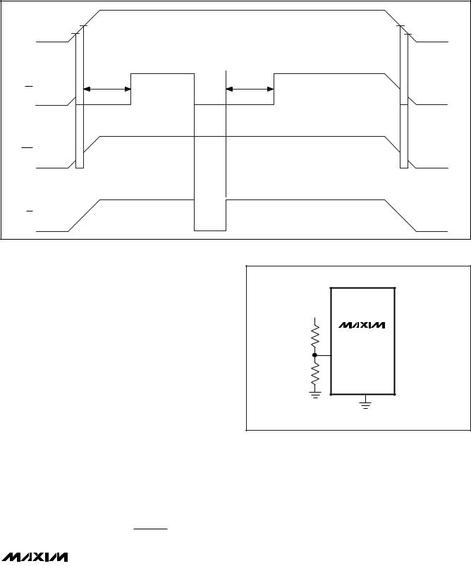
Adjustable Input Voltage (RSTIN)
The MAX6734A/MAX6735A provide an additional highimpedance comparator input with a 626mV threshold to monitor a third supply voltage. To monitor a voltage higher than 626mV, connect a resistive divider to the circuit as shown in Figure 2 to establish an externally controlled threshold voltage, VEXT_TH.
VEXT_TH = 626mV × (R1+ R2)
R2
VEXT_TH
R1 |
MAX6734A |
|
MAX6735A |
|
RSTIN |
R2 |
|
|
GND |
Figure 2. Monitoring a Third Voltage
_______________________________________________________________________________________ 9

MAX6730A–MAX6735A
Single-/Dual-/Triple-Voltage µP Supervisory Circuits with Independent Watchdog Output
The RSTIN comparator derives power from VCC1, and the input voltage must remain less than or equal to VCC1. Low leakage current at RSTIN allows the use of large-valued resistors, resulting in reduced power consumption of the system.
Watchdog
The watchdog feature monitors µP activity through the watchdog input (WDI). A rising or falling edge on WDI within the watchdog timeout period (tWD) indicates normal µP operation. WDO asserts low if WDI remains high or low for longer than the watchdog timeout period. Floating WDI does not disable the watchdog timer.
The MAX6730A–MAX6735A include a dual-mode watchdog timer to monitor µP activity. The flexible timeout architecture provides a long-period initial watchdog mode, allowing complicated systems to complete lengthy boots, and a short-period normal watchdog mode, allowing the supervisor to provide quick alerts when processor activity fails. After each reset event (VCC power-up, brownout, or manual reset), there is a long initial watchdog period of 35s (min). The long watchdog period mode provides an extended time for the system to power up and fully initialize all µP and system components before assuming responsibility for routine watchdog updates.
The usual watchdog timeout period (1.12s min) begins after the initial watchdog timeout period (tWD-L) expires or after the first transition on WDI (Figure 3). During normal operating mode, the supervisor asserts the WDO output if the µP does not update the WDI with a valid transition (high to low or low to high) within the standard timeout period (tWD-S) (1.12s min).
Connect MR to WDO to force a system reset in the event that no rising or falling edge is detected at WDI within the watchdog timeout period. WDO asserts low when no edge is detected by WDI, the RST output asserts low, the watchdog counter immediately clears, and WDO returns high. The watchdog counter restarts, using the long watchdog period, when the reset timeout period ends (Figure 4).
Ensuring a Valid Reset
Output Down to VCC = 0V
The MAX6730A–MAX6735A guarantee proper operation down to VCC = +0.8V. In applications that require valid reset levels down to VCC = 0V, use a 100kΩ pulldown resistor from RST to GND. The resistor value used is not critical, but it must be large enough not to load the reset output when VCC is above the reset threshold. For most applications, 100kΩ is adequate. Note that this configuration does not work for the opendrain outputs of MAX6730A/MAX6732A/MAX6734A.
VCC1, |
VCC |
VTH |
|
|
|
|
|
VCC2 |
|
|
|
|
|
||
RSTIN |
(MIN) |
|
|
|
|
|
|
RST |
|
tRP |
|
|
|
|
|
|
|
|
|
|
|
|
|
WDO |
|
|
|
|
|
|
|
WDI |
|
<tWD-L |
<tWD-S |
<tWD-S |
>tWD-S |
<tWD-S |
<tWD-S |
|
|
|
|
|
|
|
|
|
|
|
|
|
tWD-S |
|
|
Figure 3. Watchdog Input/Output Timing Diagram (MR and WDO Not Connected)
10 ______________________________________________________________________________________