

CHAPTER 5. ALERTING SERVICE
5.1Application
5.1.1Alerting service shall be provided:
|
a) |
for all aircraft provided with air traffic control service; |
|
|
b) |
in so far as practicable, to all other aircraft having filed |
|
|
|
a flight plan or otherwise known to the air traffic |
|
|
|
services; and |
|
|
c) |
to any aircraft known or believed to be the subject of |
|
-- |
|
unlawful interference. |
|
-`-`,,```,,,,```` |
5.1.2 Flight information centres or area control centres |
||
|
|||
`,,`,,`,`,,` |
shall serve as the central point for collecting all information |
||
relevant to a state of emergency of an aircraft operating within |
|||
|
|||
--- |
the flight information region or control area concerned and |
||
for forwarding such information to the appropriate rescue coordination centre.
5.1.3 In the event of a state of emergency arising to an aircraft while it is under the control of an aerodrome control tower or approach control unit, such unit shall notify immediately the flight information centre or area control centre responsible which shall in turn notify the rescue coordination centre, except that notification of the area control centre, flight information centre, or rescue coordination centre shall not be required when the nature of the emergency is such that the notification would be superfluous.
5.1.3.1 Nevertheless, whenever the urgency of the situation so requires, the aerodrome control tower or approach control unit responsible shall first alert and take other necessary steps to set in motion all appropriate local rescue and emergency organizations which can give the immediate assistance required.
5.2 Notification of rescue coordination centres
5.2.1 Without prejudice to any other circumstances that may render such notification advisable, air traffic services units shall, except as prescribed in 5.5.1, notify rescue coordination centres immediately an aircraft is considered to be in a state of emergency in accordance with the following:
a)Uncertainty phase when:
1)no communication has been received from an aircraft within a period of thirty minutes after the time a
communication should have been received, or from the time an unsuccessful attempt to establish communication with such aircraft was first made, whichever is the earlier, or when
2)an aircraft fails to arrive within thirty minutes of the estimated time of arrival last notified to or estimated by air traffic services units, whichever is the later,
except when no doubt exists as to the safety of the aircraft and its occupants.
b)Alert phase when:
1)following the uncertainty phase, subsequent attempts to establish communication with the aircraft or inquiries to other relevant sources have failed to reveal any news of the aircraft, or when
2)an aircraft has been cleared to land and fails to land within five minutes of the estimated time of landing and communication has not been re-established with the aircraft, or when
3)information has been received which indicates that the operating efficiency of the aircraft has been impaired, but not to the extent that a forced landing is likely,
except when evidence exists that would allay apprehension as to the safety of the aircraft and its occupants, or when
4)an aircraft is known or believed to be the subject of unlawful interference.
c)Distress phase when:
1)following the alert phase, further unsuccessful attempts to establish communication with the aircraft and more widespread unsuccessful inquiries point to the probability that the aircraft is in distress, or when
2)the fuel on board is considered to be exhausted, or to be insufficient to enable the aircraft to reach safety, or when
3)information is received which indicates that the operating efficiency of the aircraft has been impaired to the extent that a forced landing is likely, or when
4)information is received or it is reasonably certain that the aircraft is about to make or has made a forced landing,
ANNEX 11 |
5-1 |
1/11/01 |
Copyright International Civil Aviation Organization |
|
Provided by IHS under license with ICAO |
|
No reproduction or networking permitted without license from IHS |
Not for Resale |

Annex 11 — Air Traffic Services
except when there is reasonable certainty that the aircraft and its occupants are not threatened by grave and imminent danger and do not require immediate assistance.
5.2.2 The notification shall contain such of the following information as is available in the order listed:
a)INCERFA, ALERFA or DETRESFA, as appropriate to the phase of the emergency;
b)agency and person calling;
c)nature of the emergency;
d)significant information from the flight plan;
e)unit which made last contact, time and means used;
f)last position report and how determined;
g)colour and distinctive marks of aircraft;
h)dangerous goods carried as cargo;
i)any action taken by reporting office; and
j)other pertinent remarks.
5.2.2.1 Recommendation.— Such part of the information specified in 5.2.2, which is not available at the time notification is made to a rescue coordination centre, should be sought by an air traffic services unit prior to the declaration of a distress phase, if there is reasonable certainty that this phase will eventuate.
5.2.3 Further to the notification in 5.2.1, the rescue coordination centre shall, without delay, be furnished with:
a)any useful additional information, especially on the development of the state of emergency through subsequent phases; or
b)information that the emergency situation no longer exists.
Note.— The cancellation of action initiated by the rescue coordination centre is the responsibility of that centre.
5.3Use of communication facilities
Air traffic services units shall, as necessary, use all available communication facilities to endeavour to establish and
Chapter 5
maintain communication with an aircraft in a state of emergency, and to request news of the aircraft.
5.4 Plotting aircraft in a state of emergency
When a state of emergency is considered to exist, the flight of the aircraft involved shall be plotted on a chart in order to determine the probable future position of the aircraft and its maximum range of action from its last known position. The flights of other aircraft known to be operating in the vicinity of the aircraft involved shall also be plotted in order to determine their probable future positions and maximum endurance.
5.5Information to the operator
5.5.1When an area control or a flight information centre decides that an aircraft is in the uncertainty or the alert phase, it shall, when practicable, advise the operator prior to notifying the rescue coordination centre.
Note.— If an aircraft is in the distress phase, the rescue coordination centre has to be notified immediately in accordance with 5.2.1.
5.5.2 All information notified to the rescue coordination centre by an area control or flight information centre shall, whenever practicable, also be communicated, without delay, to the operator.
5.6 Information to aircraft operating in the vicinity of an aircraft in
a state of emergency
5.6.1When it has been established by an air traffic services unit that an aircraft is in a state of emergency, other aircraft known to be in the vicinity of the aircraft involved shall, except as provided in 5.6.2, be informed of the nature of the emergency as soon as practicable.
5.6.2When an air traffic services unit knows or believes that an aircraft is being subjected to unlawful interference, no reference shall be made in ATS air-ground communications to the nature of the emergency unless it has first been referred to in communications from the aircraft involved and it is certain that such reference will not aggravate the situation.
1/11/01 |
5-2 |
28/11/02 |
|
No. 41 |
--`,,```,,,,````-`-`,,`,,`,`,,`--- |
Copyright International Civil Aviation Organization |
|
Provided by IHS under license with ICAO |
|
No reproduction or networking permitted without license from IHS |
Not for Resale |
CHAPTER 6. AIR TRAFFIC SERVICES REQUIREMENTS
FOR COMMUNICATIONS
6.1 Aeronautical mobile service (air-ground communications)
6.1.1General
6.1.1.1Radiotelephony and/or data link shall be used in air-ground communications for air traffic services purposes.
Note.— Requirements for ATS units to be provided with and to maintain guard on the emergency channel 121.5 MHz are specified in Annex 10, Volumes II and V.
6.1.1.2 Where RCP types have been prescribed by States for ATM functions, ATS units shall, in addition to the requirements specified in 6.1.1.1, be provided with communication equipment which will enable them to provide ATS in accordance with the prescribed RCP type(s).
Note.— Information on RCP and associated procedures, and guidance concerning the approval process, will be contained in the Manual on Required Communication Performance (RCP) (Doc 9869) (in preparation). This document also contains references to other documents produced by States and international bodies concerning communication systems and RCP.
6.1.1.3 When direct pilot-controller two-way radiotelephony or data link communications are used for the provision of air traffic control service, recording facilities shall be provided on all such air-ground communication channels.
Note.— Requirements for retention of all automatic recordings of communications in ATC are specified in Annex 10, Volume II, 3.5.1.5.
6.1.1.4 Recordings of communications channels as required in paragraph 6.1.1.3 shall be retained for a period of at least thirty days.
should permit direct, rapid, continuous and static-free two-way communications.
6.1.3For area control service
6.1.3.1Air-ground communication facilities shall enable two-way communications to take place between a unit providing area control service and appropriately equipped aircraft flying anywhere within the control area(s).
6.1.3.2Recommendation.— Whenever practicable, airground communication facilities for area control service should permit direct, rapid, continuous and static-free two-way communications.
6.1.3.3Recommendation.— Where air-ground voice communication channels are used for area control service and are worked by air-ground communicators, suitable arrangements should be made to permit direct pilot-controller voice communications, as and when required.
6.1.4For approach control service
6.1.4.1Air-ground communication facilities shall enable direct, rapid, continuous and static-free two-way communications to take place between the unit providing approach control service and appropriately equipped aircraft under its control.
6.1.4.2Where the unit providing approach control service functions as a separate unit, air-ground communications shall be conducted over communication channels provided for its exclusive use.
6.1.2For flight information service
6.1.2.1Air-ground communication facilities shall enable two-way communications to take place between a unit providing flight information service and appropriately equipped aircraft flying anywhere within the flight information region.
6.1.5For aerodrome control service
6.1.5.1Air-ground communication facilities shall enable direct, rapid, continuous and static-free two-way communications to take place between an aerodrome control tower and
6.1.2.2Recommendation.— Whenever practicable, air- appropriately equipped aircraft operating at any distance within
ground communication facilities for flight information service |
45 km (25 NM) of the aerodrome concerned. |
ANNEX 11 |
6-1 |
22/11/07 |
|
--`,,```,,,,````-`-`,,`,,`,`,,`--- |
No. 45 |
Copyright International Civil Aviation Organization |
|
Provided by IHS under license with ICAO |
|
No reproduction or networking permitted without license from IHS |
Not for Resale |
Annex 11 — Air Traffic Services
6.1.5.2 Recommendation.— Where conditions warrant, separate communication channels should be provided for the control of traffic operating on the manoeuvring area.
6.2 Aeronautical fixed service (ground-ground communications)
6.2.1 General
Chapter 6
c) aerodrome control towers.
6.2.2.1.2 An area control centre, in addition to being connected to the flight information centre as prescribed in 6.2.2.1.1, shall have facilities for communications with the following units providing a service within its area of responsibility:
a)approach control units;
b)aerodrome control towers;
6.2.1.1 Direct-speech and/or data link communications shall be used in ground-ground communications for air traffic services purposes.
Note 1.— Indication by time of the speed with which the communication should be established is provided as a guide to communication services, particularly to determine the types of communication channels required, e.g. that “instantaneous” is intended to refer to communications which effectively provide for immediate access between controllers; “fifteen seconds” to accept switchboard operation and “five minutes” to mean methods involving retransmission.
Note 2.— Requirements for retention of all automatic recordings of communications in ATC are specified in Annex 10, Volume II, 3.5.1.5.
6.2.1.2 Where RCP types have been prescribed by States
for-- ATM functions, ATS units shall, in addition to the require- |
|
ments specified in 6.2.1.1, be provided with communication |
|
dance-`-`,,```,,,,```` |
with the prescribed RCP type(s). |
equipment which will enable them to provide ATS in accor- |
|
`,,`,,`,`,,`Note.— Information on RCP and associated procedures, |
|
--- |
|
and guidance concerning the approval process, will be con-
tained in the Manual on Required Communication Performance (RCP) (Doc 9869) (in preparation). This document also contains references to other documents produced by States and international bodies concerning communication systems and RCP.
6.2.2 Communications within a flight information region
6.2.2.1Communications between air traffic services units
6.2.2.1.1A flight information centre shall have facilities for communications with the following units providing a service within its area of responsibility:
a)the area control centre, unless collocated;
b)approach control units;
c)air traffic services reporting offices, when separately established.
6.2.2.1.3An approach control unit, in addition to being connected to the flight information centre and the area control centre as prescribed in 6.2.2.1.1 and 6.2.2.1.2, shall have facilities for communications with the associated aerodrome control tower(s) and, when separately established, the associated air traffic services reporting office(s).
6.2.2.1.4An aerodrome control tower, in addition to being connected to the flight information centre, the area control centre and the approach control unit as prescribed in 6.2.2.1.1, 6.2.2.1.2 and 6.2.2.1.3, shall have facilities for communications with the associated air traffic services reporting office, when separately established.
6.2.2.2Communications between air traffic services units and other units
6.2.2.2.1A flight information centre and an area control centre shall have facilities for communications with the following units providing a service within their respective area of responsibility:
a)appropriate military units;
b)the meteorological office serving the centre;
c)the aeronautical telecommunications station serving the centre;
d)appropriate operator’s offices;
e)the rescue coordination centre or, in the absence of such centre, any other appropriate emergency service;
f)the international NOTAM office serving the centre.
6.2.2.2.2 An approach control unit and an aerodrome control tower shall have facilities for communications with the following units providing a service within their respective area of responsibility:
a) appropriate military units;
22/11/07 |
6-2 |
No. 45 |
|
Copyright International Civil Aviation Organization |
|
Provided by IHS under license with ICAO |
|
No reproduction or networking permitted without license from IHS |
Not for Resale |
|
Chapter 6 |
|
|
|
b) rescue |
and emergency services (including ambulance, |
|
|
|
fire, etc.); |
|
|
c) |
the meteorological office serving the unit concerned; |
|
|
d) |
the aeronautical telecommunications station serving the |
|
-- |
|
unit concerned; |
|
`-`,,```,,,,```` |
e) |
the unit providing apron management service, when |
|
- |
|
separately established. |
|
---`,,`,,`,`,,` |
6.2.2.2.3 |
The communication facilities required under |
|
|
|||
6.2.2.2.1 a) and 6.2.2.2.2 a) shall include provisions for rapid and reliable communications between the air traffic services unit concerned and the military unit(s) responsible for control of interception operations within the area of responsibility of the air traffic services unit.
6.2.2.3Description of communication facilities
6.2.2.3.1The communication facilities required under 6.2.2.1, 6.2.2.2.1 a) and 6.2.2.2.2 a), b) and c) shall include provisions for:
a)communications by direct speech alone, or in combination with data link communications, whereby for the purpose of transfer of control using radar or ADS-B, the communications can be established instantaneously and for other purposes the communications can normally be established within fifteen seconds; and
b)printed communications, when a written record is required; the message transit time for such communications being no longer than five minutes.
6.2.2.3.2 Recommendation.— In all cases not covered by 6.2.2.3.1, the communication facilities should include provisions for:
a)communications by direct speech alone, or in combination with data link communications, whereby the communications can normally be established within fifteen seconds; and
b)printed communications, when a written record is required; the message transit time for such communications being no longer than five minutes.
6.2.2.3.3In all cases where automatic transfer of data to and/or from air traffic services computers is required, suitable facilities for automatic recording shall be provided.
6.2.2.3.4Recommendation.— The communication facilities required in accordance with 6.2.2.1 and 6.2.2.2 should be supplemented, as and where necessary, by facilities for other forms of visual or audio communications, for example, closed circuit television or separate information processing systems.
Annex 11 — Air Traffic Services
6.2.2.3.5The communication facilities required under
6.2.2.2.2a), b) and c) shall include provisions for communications by direct speech arranged for conference communications.
6.2.2.3.6Recommendation.— The communication facilities required under 6.2.2.2.2 d) should include provisions for communications by direct speech arranged for conference communications, whereby the communications can normally be established within fifteen seconds.
6.2.2.3.7All facilities for direct-speech or data link communications between air traffic services units and between air traffic services units and other units described under
6.2.2.2.1and 6.2.2.2.2 shall be provided with automatic
recording.
6.2.2.3.8Recordings of data and communications as required in 6.2.2.3.3 and 6.2.2.3.7 shall be retained for a period of at least thirty days.
6.2.3 Communications between flight information regions
6.2.3.1 Flight information centres and area control centres shall have facilities for communications with all adjacent flight information centres and area control centres.
6.2.3.1.1These communication facilities shall in all cases include provisions for messages in a form suitable for retention as a permanent record, and delivery in accordance with transit times specified by regional air navigation agreements.
6.2.3.1.2Unless otherwise prescribed on the basis of regional air navigation agreements, facilities for communications between area control centres serving contiguous control areas shall, in addition, include provisions for directspeech and, where applicable, data link communications, with automatic recording, whereby for the purpose of transfer of control using radar, ADS-B or ADS-C data, the communications can be established instantaneously and for other purposes the communications can normally be established within fifteen seconds.
6.2.3.1.3When so required by agreement between the States concerned in order to eliminate or reduce the need for interceptions in the event of deviations from assigned track, facilities for communications between adjacent flight information centres or area control centres other than those mentioned in 6.2.3.1.2 shall include provisions for direct speech alone, or in combination with data link communications. The communication facilities shall be provided with automatic recording.
6.2.3.1.4Recommendation.— The communication facilities in 6.2.3.1.3 should permit communications to be established normally within fifteen seconds.
6-3 |
22/11/07 |
1/11/01 |
|
|
No. 45 |
Copyright International Civil Aviation Organization |
|
Provided by IHS under license with ICAO |
|
No reproduction or networking permitted without license from IHS |
Not for Resale |

Annex 11 — Air Traffic Services
6.2.3.2 Recommendation.— Adjacent ATS units should be connected in all cases where special circumstances exist.
Note.— Special circumstances may be due to traffic density, types of aircraft operations and/or the manner in which the airspace is organized and may exist even if the control areas and/or control zones are not contiguous or have not (yet) been established.
6.2.3.3 Recommendation.— Wherever local conditions are such that it is necessary to clear aircraft into an adjacent control area prior to departure, an approach control unit and/ or aerodrome control tower should be connected with the area control centre serving the adjacent area.
6.2.3.4 Recommendation.— The communication facilities in 6.2.3.2 and 6.2.3.3 should include provisions for communications by direct speech alone, or in combination with data link communications, with automatic recording, whereby for the purpose of transfer of control using radar, ADS-B or ADS-C data, the communications can be established instantaneously and for other purposes the communications can normally be established within fifteen seconds.
--6.2.3.5 In all cases where automatic exchange of data
between air traffic services computers is required, suitable |
|
facilities`-`,,```,,,,```` |
for automatic recording shall be provided. |
`,,`,,`,`,,`-6.2.3.6 Recordings of data and communications as |
|
--- |
|
required in 6.2.3.5 shall be retained for a period of at least thirty days.
6.2.4 Procedures for direct-speech communications
Recommendation.— Appropriate procedures for directspeech communications should be developed to permit immediate connections to be made for very urgent calls concerning the safety of aircraft, and the interruption, if necessary, of less urgent calls in progress at the time.
Chapter 6
6.3 Surface movement control service
6.3.1Communications for the control of vehicles other than aircraft
on manoeuvring areas at controlled aerodromes
6.3.1.1Two-way radiotelephony communication facilities shall be provided for aerodrome control service for the control of vehicles on the manoeuvring area, except where communication by a system of visual signals is deemed to be adequate.
6.3.1.2Where conditions warrant, separate communication channels shall be provided for the control of vehicles on the manoeuvring area. Automatic recording facilities shall be provided on all such channels.
6.3.1.3Recordings of communications as required in
6.3.1.2shall be retained for a period of at least thirty days.
Note.— See also Annex 10, Volume II, 3.5.1.5.
6.4Aeronautical radio navigation service
6.4.1 Automatic recording of surveillance data
6.4.1.1Surveillance data from primary and secondary radar equipment or other systems (e.g. ADS-B, ADS-C), used as an aid to air traffic services, shall be automatically recorded for use in accident and incident investigations, search and rescue, air traffic control and surveillance systems evaluation and training.
6.4.1.2Automatic recordings shall be retained for a period of at least thirty days. When the recordings are pertinent to accident and incident investigations, they shall be retained for longer periods until it is evident that they will no longer be required.
22/11/07 |
6-4 |
No. 45 |
|
Copyright International Civil Aviation Organization |
|
Provided by IHS under license with ICAO |
|
No reproduction or networking permitted without license from IHS |
Not for Resale |
CHAPTER 7. AIR TRAFFIC SERVICES REQUIREMENTS
FOR INFORMATION
7.1 Meteorological information |
data for setting altimeters, for locations specified by the flight |
|
information centre or area control centre concerned. |
7.1.1 General |
|
7.1.1.1Air traffic services units shall be supplied with up-to-date information on existing and forecast meteorological conditions as necessary for the performance of their respective functions. The information shall be supplied in such a form as to require a minimum of interpretation on the part of air traffic services personnel and with a frequency which satisfies the requirements of the air traffic services units concerned.
7.1.1.2Recommendation.— Air traffic services units should be supplied with available detailed information on the location, vertical extent, direction and rate of movement of meteorological phenomena in the vicinity of the aerodrome, and particularly in the climb-out and approach areas, which could be hazardous to aircraft operations.
Note.— The meteorological phenomena are listed in Annex 3, Chapter 4, 4.6.8.
7.1.1.3 Recommendation.— When computer-processed upper air data are made available to air traffic services units in digital form for use by air traffic services computers, the contents, format and transmission arrangements should be as agreed between the Meteorological Authority and the appropriate ATS Authority.
7.1.2 Flight information centres and area control centres
7.1.2.1 Flight information centres and area control centres shall be supplied with meteorological information as described in Annex 3, Appendix 9, 1.3, particular emphasis being given to the occurrence or expected occurrence of weather deterioration as soon as this can be determined. These reports and forecasts shall cover the flight information region or control area and such other areas as may be determined on the basis of regional air navigation agreements.
Note.— For the purpose of this provision, certain changes in meteorological conditions are construed as deterioration in a weather element, although they are not ordinarily considered as such. An increase in temperature may, for example, adversely affect the operation of certain types of aircraft.
7.1.3 Units providing approach control service
7.1.3.1 Units providing approach control service shall be supplied with meteorological information as described in Annex 3, Appendix 9, 1.2 for the airspace and the aerodromes with which they are concerned. Special reports and amendments to forecasts shall be communicated to the units providing approach control service as soon as they are necessary in accordance with established criteria, without waiting for the next routine report or forecast. Where multiple anemometers are used, the indicators to which they are related shall be clearly marked to identify the runway and section of the runway monitored by each anemometer.
Note.— See Note following 7.1.2.1.
7.1.3.2Units providing approach control service shall be provided with current pressure data for setting altimeters, for locations specified by the unit providing approach control service.
7.1.3.3Units providing approach control service for final approach, landing and take-off shall be equipped with surface wind display(s). The display(s) shall be related to the same location(s) of observation and be fed from the same sensor(s) as the corresponding display(s) in the aerodrome control tower and in the meteorological station, where such a station exists.
7.1.3.4Units providing approach control service for final approach, landing and take-off at aerodromes where runway visual range values are assessed by instrumental means shall be equipped with display(s) permitting read-out of the current runway visual range value(s). The display(s) shall be related to the same location(s) of observation and be fed from the same sensor(s) as the corresponding displays in the aerodrome control tower and in the meteorological station, where such a station exists.
7.1.3.5Recommendation.— Units providing approach control service for final approach, landing and take-off at aerodromes where the height of cloud base is assessed by instrumental means should be equipped with display(s) permit-
7.1.2.2Flight information centres and area control centres ting read-out of the current value(s) of the height of cloud
shall be provided, at suitable intervals, with current pressure |
|
base. The displays should be related to the same location(s) of |
|
ANNEX 11 |
7-1 |
22/11/07 |
|
|
|
|
No. 45 |
Copyright International Civil Aviation Organization |
|
Provided by IHS under license with ICAO |
|
No reproduction or networking permitted without license from IHS |
Not for Resale |
Annex 11 — Air Traffic Services
observations and be fed from the same sensor(s) as the corresponding display(s) in the aerodrome control tower and in the meteorological station, where such a station exists.
7.1.3.6 Units providing approach control service for final approach, landing and take-off shall be supplied with information on wind shear which could adversely affect aircraft on the approach or take-off paths or during circling approach.
Note.— Provisions concerning the issuance of wind shear warnings and alerts and ATS requirements for meteorological information are given in Annex 3, Chapter 7 and Appendices 6 and 9.
Chapter 7
aircraft on the approach or take-off paths or during circling approach and aircraft on the runway during the landing roll or take-off run.
7.1.4.7 Recommendation.— Aerodrome control towers and/or other appropriate units should be supplied with aerodrome warnings.
Note.— The meteorological conditions for which aerodrome warnings are issued are listed in Annex 3, Appendix 6, 5.1.3.
--
`,,```,,,,````-`- |
7.1.4 Aerodrome control towers |
7.1.4.1 Aerodrome control towers shall be supplied with |
`,,`,,`,`,,`meteorological information as described in Annex 3, ---
Appendix 9, 1.1 for the aerodrome with which they are concerned. Special reports and amend-ments to forecasts shall be communicated to the aerodrome control towers as soon as they are necessary in accordance with established criteria, without waiting for the next routine report or forecast.
Note.— See Note following 7.1.2.1.
7.1.4.2Aerodrome control towers shall be provided with current pressure data for setting altimeters for the aerodrome concerned.
7.1.4.3Aerodrome control towers shall be equipped with surface wind display(s). The display(s) shall be related to the same location(s) of observation and be fed from the same sensor(s) as the corresponding display(s) in the meteorological station, where such a station exists. Where multiple sensor(s) are used, the displays to which they are related shall be clearly marked to identify the runway and section of the runway monitored by each sensor.
7.1.4.4Aerodrome control towers at aerodromes where runway visual range values are measured by instrumental means shall be equipped with display(s) permitting read-out of the current runway visual range value(s). The display(s) shall be related to the same location(s) of observation and be fed from the same sensor(s) as the corresponding display(s) in the meteorological station, where such a station exists.
7.1.4.5Recommendation.— Aerodrome control towers at aerodromes where the height of cloud base is assessed by instrumental means should be equipped with display(s) permitting read-out of the current value(s) of the height of cloud base. The displays should be related to the same location(s) of observations and be fed from the same sensor(s) as the corresponding display(s) in the meteorological station, where such a station exists.
7.1.4.6Aerodrome control towers shall be supplied with information on wind shear which could adversely affect
22/11/07 |
7-2 |
No. 45 |
|
7.1.5 Communication stations
Where necessary for flight information purposes, current meteorological reports and forecasts shall be supplied to communication stations. A copy of such information shall be forwarded to the flight information centre or the area control centre.
7.2 Information on aerodrome conditions and the operational status of
associated facilities
Aerodrome control towers and units providing approach control service shall be kept currently informed of the operationally significant conditions of the movement area, including the existence of temporary hazards, and the operational status of any associated facilities at the aerodrome(s) with which they are concerned.
7.3 Information on the operational status of navigation aids
7.3.1ATS units shall be kept currently informed of the operational status of non-visual navigation aids, and those visual aids essential for take-off, departure, approach and landing procedures within their area of responsibility and those visual and non-visual aids essential for surface movement.
7.3.2Recommendation.— Information on the operational status, and any changes thereto, of visual and nonvisual aids as referred to in 7.3.1 should be received by the appropriate ATS unit(s) on a timely basis consistent with the use of the aid(s) involved.
Note.— Guidance material regarding the provision of information to ATS units in respect to visual and non-visual navigation aids is contained in the Air Traffic Services Planning Manual (Doc 9426). Specifications for monitoring visual aids are contained in Annex 14, Volume I, and related guidance material is in the Aerodrome Design Manual (Doc 9157), Part 5. Specifications for monitoring non-visual aids are contained in Annex 10, Volume I.
Copyright International Civil Aviation Organization |
|
Provided by IHS under license with ICAO |
|
No reproduction or networking permitted without license from IHS |
Not for Resale |

Chapter 7
7.4 Information on unmanned free balloons
Operators of unmanned free balloons shall keep the appropriate air traffic services units informed of details of flights of unmanned free balloons in accordance with the provisions contained in Annex 2.
Annex 11 — Air Traffic Services
7.5.2 Area control centres and flight information centres shall be provided with volcanic ash advisory information issued by the associated VAAC.
Note.— VAACs are designated by regional air navigation agreements in accordance with Annex 3, 3.5.1.
7.5Information concerning volcanic activity
7.5.1ATS units shall be informed, in accordance with local agreement, of pre-eruption volcanic activity, volcanic eruptions and volcanic ash cloud which could affect airspace used by flights within their area of responsibility.
7.6 Information concerning radioactive materials and toxic chemical “clouds”
ATS units shall be informed, in accordance with local agreement, of the release into the atmosphere of radioactive materials or toxic chemicals which could affect airspace used by flights within their area of responsibility.
--`,,```,,,,````-`-`,,`,,`,`,,`---
7-3 |
22/11/07 |
|
No. 45 |
Copyright International Civil Aviation Organization |
|
Provided by IHS under license with ICAO |
|
No reproduction or networking permitted without license from IHS |
Not for Resale |
APPENDIX 1. PRINCIPLES GOVERNING THE IDENTIFICATION OF RNP TYPES
AND THE IDENTIFICATION OF ATS ROUTES OTHER THAN
STANDARD DEPARTURE AND ARRIVAL ROUTES
(Chapter 2, Sections 2.7 and 2.12 refer)
Note.— See Appendix 3 concerning the identification of standard departure and arrival routes and associated procedures. Guidance material on the establishment of these routes and procedures is contained in the Air Traffic Services Planning Manual (Doc 9426).
1. Designators for ATS routes and RNP types
1.1 The purpose of a system of route designators and required navigation performance (RNP) type(s) applicable to specified ATS route segment(s), route(s) or area is to allow both pilots and ATS, taking into account automation requirements:
a)to make unambiguous reference to any ATS route without the need to resort to the use of geographical coordinates or other means in order to describe it;
c)be usable by both ground and airborne automation systems;
d)permit utmost brevity in operational use; and
e)provide sufficient possibility of extension to cater for any future requirements without the need for fundamental changes.
1.3 Controlled, advisory and uncontrolled ATS routes, with the exception of standard arrival and departure routes, shall therefore be identified as specified hereafter.
2.Composition of designator
2.1The ATS route designator shall consist of a basic designator supplemented, if necessary, by:
b) to relate an ATS route to a specific vertical structure of |
a) |
one prefix as prescribed in 2.3; and |
||||
|
|
|||||
the airspace, as applicable; |
|
b) one additional letter as prescribed in 2.4. |
||||
c) to indicate a required level of navigation performance |
2.1.1 The number of characters required to compose the |
|||||
accuracy, when operating along an ATS route or within |
designator shall not exceed six characters. |
|||||
a specified area; and |
|
|
|
|||
d) to indicate that a route is used primarily or exclusively |
2.1.2 The number of characters required to compose the |
|||||
designator should, whenever possible, be kept to a maximum |
||||||
by certain types of aircraft. |
|
|||||
|
of five characters. |
|||||
|
|
|
|
|||
Note 1.— |
Prior |
to the global introduction of |
RNP, all |
2.2 The basic designator shall consist of one letter of the |
||
references in |
this |
appendix to RNP also apply |
to area |
|||
alphabet followed by a number from 1 to 999. |
||||||
navigation (RNAV) routes, where navigation performance |
||||||
|
|
|||||
accuracy requirements have been specified. |
|
2.2.1 Selection of the letter shall be made from those |
||||
|
|
|
|
|||
Note 2.— Specifications governing the publication of |
listed hereunder: |
|||||
|
|
|||||
RNP types are given in Annex 4, Chapter 7, and Annex 15, |
a) |
A, B, G, R for routes which form part of the regional |
||||
Appendix 1. |
|
|
|
|||
|
|
|
|
networks of ATS routes and are not area navigation |
||
|
|
|
|
|
||
Note 3.— In relation to this appendix and for flight |
|
routes; |
||||
planning purposes, a prescribed RNP type is not considered |
b) L, M, N, P for area navigation routes which form part of |
|||||
an integral part of the ATS route designator. |
|
|||||
|
|
the regional networks of ATS routes; |
||||
|
|
|
|
|
||
1.2 In order to meet this purpose, the designation system |
c) H, J, V, W for routes which do not form part of the |
|||||
shall: |
|
|
|
|||
|
|
|
|
|
regional networks of ATS routes and are not area |
|
a) permit the identification of any ATS route in a simple |
|
navigation routes; |
||||
and unique manner; |
|
d) Q, T, Y, Z for area navigation routes which do not form |
||||
b) avoid redundancy; |
|
|||||
|
|
part of the regional networks of ATS routes. |
||||
ANNEX 11 |
|
|
APP 1-1 |
22/11/07 |
||
|
|
1/11/01 |
||||
|
|
|
|
|
No. 45 |
|
--`,,```,,,,````-`-`,,`,,`,`,,`---
Copyright International Civil Aviation Organization |
|
Provided by IHS under license with ICAO |
|
No reproduction or networking permitted without license from IHS |
Not for Resale |

Annex 11 — Air Traffic Services
2.3 Where applicable, one supplementary letter shall be added as a prefix to the basic designator in accordance with the following:
a)K to indicate a low-level route established for use primarily by helicopters;
b)U to indicate that the route or portion thereof is established in the upper airspace;
c)S to indicate a route established exclusively for use by supersonic aircraft during acceleration, deceleration and while in supersonic flight.
2.4When prescribed by the appropriate ATS authority or on the basis of regional air navigation agreements, a supplementary letter may be added after the basic designator of the ATS route in question in order to indicate the type of service provided or the turn performance required on the route in question in accordance with the following:
a)for RNP 1 routes at and above FL 200, the letter Y to
indicate that |
all |
turns |
on |
the |
route between |
30 |
and |
90 degrees shall be made within the allowable RNP |
|||||||
tolerance of |
a |
tangential |
arc |
between the |
straight |
||
leg segments defined |
with a |
radius of 22.5 |
NM |
||||
(e.g. A123Y[1]); |
|
|
|
|
|
|
|
b) for RNP 1 routes at and below FL 190, the letter Z to
indicate |
that |
all turns on the route between |
30 and |
|
90 degrees shall be made within the allowable |
RNP |
|||
tolerance |
of |
a tangential arc between the |
straight |
|
leg segments |
defined with a radius of |
15 |
NM |
|
(e.g. G246Z[1]); |
|
|
||
c)the letter F to indicate that on the route or portion thereof advisory service only is provided;
d)the letter G to indicate that on the route or portion thereof flight information service only is provided.
Note 1.— Due to limitations in the display equipment on board aircraft, the supplementary letters “F”, “G”, “Y” or “Z” may not be displayed to the pilot.
Note 2.— Implementation of a route or a portion thereof as controlled route, advisory route or flight information route is indicated in aeronautical charts and aeronautical information publications in accordance with the provisions in Annexes 4 and 15.
Note 3.— The conditions under which States may specify the controlled turn performance referred to in 2.4 a) and b) are discussed in the Manual on Required Navigation Performance (RNP) (Doc 9613).
Appendix 1
3.Assignment of basic designators
3.1Basic ATS route designators shall be assigned in accordance with the following principles.
3.1.1 The same basic designator shall be assigned to a main trunk route throughout its entire length, irrespective of terminal control areas, States or regions traversed.
Note.— This is of particular importance where automated ATS data processing and computerized airborne navigation equipment is used.
3.1.2Where two or more trunk routes have a common segment, the segment in question shall be assigned each of the designators of the routes concerned, except where this would present difficulties in the provision of air traffic service, in which case, by common agreement, one designator only shall be assigned.
3.1.3A basic designator assigned to one route shall not be assigned to any other route.
3.1.4States’ requirements for designators shall be notified to the Regional Offices of ICAO for coordination.
4. Use of designators in communications
4.1In printed communications, the designator shall be expressed at all times by not less than two and not more than six characters.
4.2In voice communications, the basic letter of a designator shall be spoken in accordance with the ICAO spelling alphabet.
4.3Where the prefixes K, U or S specified in 2.3 are used, they shall, in voice communications, be spoken as follows:
K — KOPTER
U — UPPER
S — SUPERSONIC
The word “kopter” shall be pronounced as in the word “helicopter” and the words “upper” and “supersonic” as in the English language.
4.4Where the letters “F”, “G”, “Y” or “Z” specified in
2.4above are used, the flight crew should not be required to use them in voice communications.
1/11/01 |
APP 1-2 |
|
--`,,```,,,,````-`-`,,`,,`,`,,`--- |
Copyright International Civil Aviation Organization |
|
Provided by IHS under license with ICAO |
|
No reproduction or networking permitted without license from IHS |
Not for Resale |
APPENDIX 2. PRINCIPLES GOVERNING THE ESTABLISHMENT AND
IDENTIFICATION OF SIGNIFICANT POINTS
(Chapter 2, Section 2.14 refers)
1.Establishment of significant points
1.1Significant points should, whenever possible, be established with reference to ground-based radio navigation aids, preferably VHF or higher frequency aids.
1.2Where such ground-based radio navigation aids do not exist, significant points shall be established at locations which can be determined by self-contained airborne navigation aids, or, where navigation by visual reference to the ground is to be effected, by visual observation. Specific points may be designated as ‘‘transfer of control’’ points by agreement between adjacent air traffic control units or control positions concerned.
2.Designators for significant points
marked by the site of a radio navigation aid
2.1 Plain language name for significant points marked by the site of a radio navigation aid
2.1.1Whenever practicable, significant points shall be named with reference to an identifiable and preferably prominent geographical location.
2.1.2In selecting a name for the significant point, care shall be taken to ensure that the following conditions are met:
a)the name shall not create difficulties in pronunciation for pilots or ATS personnel when speaking in the language used in ATS communications. Where the name of a geographical location in the national language selected for designating a significant point gives rise to difficulties in pronunciation, an abbreviated or contracted version of this name, which retains as much of its geographical significance as possible, shall be selected;
Example: FUERSTENFELDBRUCK = FURSTY
b)the name shall be easily recognizable in voice communications and shall be free of ambiguity with those of other significant points in the same general
area. In addition, the name shall not create confusion with respect to other communications exchanged between air traffic services and pilots;
c)the name should, if possible, consist of at least six letters and form two syllables and preferably not more than three;
d)the selected name shall be the same for both the significant point and the radio navigation aid marking it.
2.2Composition of coded designators for significant points marked by the site
of a radio navigation aid
2.2.1The coded designator shall be the same as the radio identification of the radio navigation aid. It shall be so composed, if possible, as to facilitate association with the name of the point in plain language.
2.2.2Coded designators shall not be duplicated within 1 100 km (600 NM) of the location of the radio navigation aid concerned, except as noted hereunder.
Note.— When two radio navigation aids operating in different bands of the frequency spectrum are situated at the same location, their radio identifications are normally the same.
2.3 States’ requirements for coded designators shall be notified to the Regional Offices of ICAO for coordination.
3. Designators for significant points not marked by the site of
a radio navigation aid
3.1Where a significant point is required at a position not marked by the site of a radio navigation aid, the significant point shall be designated by a unique five-letter pronounceable “name-code”. This name-code designator then serves as the name as well as the coded designator of the significant point.
3.2This name-code designator shall be selected so as to avoid any difficulties in pronunciation by pilots or ATS
ANNEX 11 |
APP 2-1 |
22/11/07 |
1/11/01 |
||
|
|
No. 45 |
--`,,```,,,,````-`-`,,`,,`,`,,`---
Copyright International Civil Aviation Organization |
|
Provided by IHS under license with ICAO |
|
No reproduction or networking permitted without license from IHS |
Not for Resale |
Annex 11 — Air Traffic Services
personnel when speaking in the language used in ATS communications.
Examples: ADOLA, KODAP
3.3The name-code designator shall be easily recognizable in voice communications and shall be free of ambiguity with those used for other significant points in the same general area.
3.4The name-code designator assigned to a significant point shall not be assigned to any other significant point. When there is a need to relocate a significant point, a new name-code designator shall be chosen. In cases when a State wishes to keep the allocation of specific name-codes for re-use at a different location, such name-codes shall not be used until after a period of at least six months.
3.5 States’ requirements for name-code designators shall be notified to the Regional Offices of ICAO for coordination.
3.6 In areas where no system of fixed routes is established or where the routes followed by aircraft vary depending on operational considerations, significant points shall be determined and reported in terms of World Geodetic System — 1984 (WGS-84) geographical coordinates, except that permanently established significant points serving as exit and/or entry points into such areas shall be designated in accordance with the applicable provisions in 2 or 3.
4. Use of designators in communications
4.1Normally the name selected in accordance with 2 or 3 shall be used to refer to the significant point in voice communications. If the plain language name for a significant point marked by the site of a radio navigation aid selected in accordance with 2.1 is not used, it shall be replaced by the coded designator which, in voice communications, shall be spoken in accordance with the ICAO spelling alphabet.
4.2In printed and coded communications, only the coded designator or the selected name-code shall be used to refer to a significant point.
Appendix 2
a)the type of air traffic services provided;
b)the amount of traffic normally encountered;
c)the accuracy with which aircraft are capable of adhering to the current flight plan;
d)the speed of the aircraft;
e)the separation minima applied;
f)the complexity of the airspace structure;
g)the control method(s) employed;
h)the start or end of significant phases of a flight (climb, descent, change of direction, etc.);
i)transfer of control procedures;
j)safety and search and rescue aspects;
k)the cockpit and air-ground communication workload.
5.3Reporting points shall be established either as “compulsory” or as “on-request”.
5.4In establishing “compulsory” reporting points the following principles shall apply:
a)compulsory reporting points shall be limited to the minimum necessary for the routine provision of information to air traffic services units on the progress of aircraft in flight, bearing in mind the need to keep cockpit and controller workload and air-ground communications load to a minimum;
b)the availability of a radio navigation aid at a location should not necessarily determine its designation as a compulsory reporting point;
c)compulsory reporting points should not necessarily be established at flight information region or control area boundaries.
5.5 “On-request” reporting points may be established in relation to the requirements of air traffic services for additional position reports when traffic conditions so demand.
5. Significant points used for reporting purposes
5.1In order to permit ATS to obtain information regarding the progress of aircraft in flight, selected significant points may need to be designated as reporting points.
5.2In establishing such points, consideration shall be given to the following factors:
5.6The designation of compulsory and on-request reporting points shall be reviewed regularly with a view to keeping the requirements for routine position reporting to the minimum necessary to ensure efficient air traffic services.
5.7Routine reporting over compulsory reporting points should not systematically be made mandatory for all flights in all circumstances. In applying this principle, particular attention shall be given to the following:
22/11/07 |
APP 2-2 |
1/11/01 |
No. 45
--`,,```,,,,````-`-`,,`,,`,`,,`---
Copyright International Civil Aviation Organization |
|
Provided by IHS under license with ICAO |
|
No reproduction or networking permitted without license from IHS |
Not for Resale |

Appendix 2 |
Annex 11 — Air Traffic Services |
a)high-speed, high-flying aircraft should not be required to make routine position reports over all reporting points established as compulsory for low-speed, low-flying aircraft;
b)aircraft transiting through a terminal control area should not be required to make routine position reports as frequently as arriving and departing aircraft.
5.8 In areas where the above principles regarding the establishment of reporting points would not be practicable, a reporting system with reference to meridians of longitude or parallels of latitude expressed in whole degrees may be established.
APP 2-3 |
22/11/07 |
1/11/01 |
|
|
No. 45 |
--`,,```,,,,````-`-`,,`,,`,`,,`---
Copyright International Civil Aviation Organization |
|
Provided by IHS under license with ICAO |
|
No reproduction or networking permitted without license from IHS |
Not for Resale |
APPENDIX 3. PRINCIPLES GOVERNING THE IDENTIFICATION OF STANDARD DEPARTURE AND ARRIVAL ROUTES
AND ASSOCIATED PROCEDURES
(See Chapter 2, 2.12.3)
Note.— Material relating to the establishment of standard departure and arrival routes and associated procedures is contained in the Air Traffic Services Planning Manual
(Doc 9426).
1. Designators for standard departure and arrival routes and associated procedures
Note.— In the following text the term “route” is used in the meaning of “route and associated procedures”.
1.1The system of designators shall:
a)permit the identification of each route in a simple and unambiguous manner;
b)make a clear distinction between:
—departure routes and arrival routes;
—departure or arrival routes and other ATS routes;
—routes requiring navigation by reference to groundbased radio aids or self-contained airborne aids, and routes requiring navigation by visual reference to the ground;
c)be compatible with ATS and aircraft data processing and display requirements;
d)be of utmost brevity in its operational application;
e)avoid redundancy;
f)provide sufficient possibility for extension to cater for any future requirements without the need for fundamental changes.
1.2 Each route shall be identified by a plain language designator and a corresponding coded designator.
2.Composition of designators
2.1Plain language designator
2.1.1The plain language designator of a standard departure or arrival route shall consist of:
a)a basic indicator; followed by
b)a validity indicator; followed by
c)a route indicator, where required; followed by
d)the word “departure” or “arrival”; followed by
e)the word “visual”, if the route has been established for use by aircraft operating in accordance with the visual flight rules (VFR).
2.1.2The basic indicator shall be the name or name-code of the significant point where a standard departure route terminates or a standard arrival route begins.
2.1.3The validity indicator shall be a number from 1
to 9.
2.1.4The route indicator shall be one letter of the alphabet. The letters “I” and “O” shall not be used.
2.2Coded designator
The coded designator of a standard departure or arrival route, instrument or visual, shall consist of:
a)the coded designator or name-code of the significant point described in 2.1.1 a); followed by
b)the validity indicator in 2.1.1 b); followed by
c)the route indicator in 2.1.1 c), where required.
Note.— Limitations in the display equipment on board
1.3The designators shall, in voice communications, be aircraft may require shortening of the basic indicator, if that
easily recognizable as relating to a standard departure or arrival route and shall not create any difficulties in pronunciation for pilots and ATS personnel.
indicator is a five-letter name-code, e.g. KODAP. The manner in which such an indicator is shortened is left to the discretion of operators.
ANNEX 11 |
APP 3-1 |
22/11/07 |
1/11/01 |
||
|
|
No. 45 |
--`,,```,,,,````-`-`,,`,,`,`,,`---
Copyright International Civil Aviation Organization |
|
Provided by IHS under license with ICAO |
|
No reproduction or networking permitted without license from IHS |
Not for Resale |
Annex 11 — Air Traffic Services
3.Assignment of designators
3.1Each route shall be assigned a separate designator.
3.2To distinguish between two or more routes which relate to the same significant point (and therefore are assigned the same basic indicator), a separate route indicator as described in 2.1.4 shall be assigned to each route.
4.Assignment of validity indicators
4.1A validity indicator shall be assigned to each route to identify the route which is currently in effect.
4.2The first validity indicator to be assigned shall be the number “1”.
4.3Whenever a route is amended, a new validity indicator, consisting of the next higher number, shall be assigned. The number “9” shall be followed by the number “1”.
5.Examples of plain language and coded designators
5.1Example 1: Standard departure route — instrument:
a) Plain language |
BRECON ONE |
designator: |
DEPARTURE |
b) Coded designator: |
BCN 1 |
5.1.1 Meaning: The designator identifies a standard instrument departure route which terminates at the significant point BRECON (basic indicator). BRECON is a radio navigation facility with the identification BCN (basic indicator of the coded designator). The validity indicator ONE (1 in the coded designator) signifies either that the original version of the route is still in effect or that a change has been made from the previous version NINE (9) to the now effective version ONE (1) (see 4.3). The absence of a route indicator (see 2.1.4 and 3.2) signifies that only one route, in this case a departure route, has been established with reference to BRECON.
5.2Example 2: Standard arrival route — instrument:
a) Plain language |
KODAP TWO ALPHA |
designator: |
ARRIVAL |
b) Coded designator: |
KODAP 2 A |
5.2.1 Meaning: This designator identifies a standard instrument arrival route which begins at the significant point KODAP (basic indicator). KODAP is a significant point not marked by the site of a radio navigation facility and
Appendix 3
therefore assigned a five-letter name-code in accordance with Appendix 2. The validity indicator TWO (2) signifies that a change has been made from the previous version ONE (1) to the now effective version TWO (2). The route indicator ALPHA (A) identifies one of several routes established with reference to KODAP and is a specific character assigned to this route.
5.3 Example 3: Standard departure route — visual:
a) Plain language |
ADOLA FIVE BRAVO |
designator |
DEPARTURE VISUAL |
b) Coded designator: |
ADOLA 5 B |
5.3.1Meaning: This designator identifies a standard departure route for controlled VFR flights which terminates at ADOLA, a significant point not marked by the site of a radio navigation facility. The validity indicator FIVE (5) signifies that a change has been made from the previous version FOUR
(4)to the now effective version FIVE (5). The route indicator BRAVO (B) identifies one of several routes established with reference to ADOLA.
6.Composition of designators for MLS/RNAV approach procedures
6.1Plain language designator
6.1.1The plain language designator of an MLS/RNAV approach procedure shall consist of:
a)“MLS”; followed by
b)a basic indicator; followed by
c)a validity indicator; followed by
d)a route indicator; followed by
e)the word “approach”; followed by
f)the designator of the runway for which the procedure is designed.
6.1.2The basic indicator shall be the name or name-code of the significant point where the approach procedure begins.
6.1.3The validity indicator shall be a number from 1 to 9.
6.1.4The route indicator shall be one letter of the alphabet. The letters “I” and “O” shall not be used.
6.1.5The designator of the runway shall be in accordance with Annex 14, Volume I, 5.2.2.
1/11/01 APP 3-2
--`,,```,,,,````-`-`,,`,,`,`,,`---
Copyright International Civil Aviation Organization |
|
Provided by IHS under license with ICAO |
|
No reproduction or networking permitted without license from IHS |
Not for Resale |

Appendix 3
6.2Coded designator
6.2.1The coded designator of an MLS/RNAV approach procedure shall consist of:
a)“MLS”; followed by
b)the coded designator or name-code of the significant point described in 6.1.1 b); followed by
c)the validity indicator in 6.1.1 c); followed by
d)the route indicator in 6.1.1 d); followed by
e)the runway designator in 6.1.1 f).
6.3Assignment of designators
6.3.1The assignment of designators for MLS/RNAV approach procedures shall be in accordance with paragraph 3. Procedures having identical tracks but different flight profiles shall be assigned separate route indicators.
6.3.2The route indicator letter for MLS/RNAV approach procedures shall be assigned uniquely to all approaches at an airport until all the letters have been used. Only then shall the route indicator letter be repeated. The use of the same route indicator for two routes using the same MLS ground facility shall not be permitted.
6.3.3The assignment of validity indicator for approach procedures shall be in accordance with paragraph 4.
6.4Example of plain language
and coded designators
6.4.1 Example: |
|
a) Plain language |
MLS HAPPY ONE ALPHA |
designator: |
APPROACH RUNWAY |
|
ONE EIGHT LEFT |
b) Coded designator: |
MLS HAPPY 1 A 18L |
Annex 11 — Air Traffic Services
6.4.2 Meaning: The designator identifies an MLS/RNAV approach procedure which begins at the significant point HAPPY (basic indicator). HAPPY is a significant point not marked by the site of a radio navigation facility and therefore assigned a five-letter name-code in accordance with Appendix 2. The validity indicator ONE (1) signifies that either the original version of the route is still in effect or a change has been made from the previous version NINE (9) to the now effective version ONE (1). The route indicator ALPHA (A) identifies one of several routes established with reference to HAPPY and is a specific character assigned to this route.
7.Use of designators in communications
7.1In voice communications, only the plain language designator shall be used.
Note.— For the purpose of identification of routes, the words “departure”, “arrival” and “visual” described in 2.1.1 d) and 2.1.1 e) are considered to be an integral element of the plain language designator.
7.2 In printed or coded communications, only the coded designator shall be used.
8. Display of routes and procedures to air traffic control
8.1A detailed description of each currently effective standard departure and/or arrival route/approach procedure, including the plain language designator and the coded designator, shall be displayed at the working positions at which the routes/procedures are assigned to aircraft as part of an ATC clearance, or are otherwise of relevance in the provision of air traffic control services.
8.2Whenever possible, a graphic portrayal of the routes/ procedures shall also be displayed.
--`,,```,,,,````-`-`,,`,,`,`,,`---
APP 3-3 |
1/11/01 |
Copyright International Civil Aviation Organization |
|
Provided by IHS under license with ICAO |
|
No reproduction or networking permitted without license from IHS |
Not for Resale |

APPENDIX 4. ATS AIRSPACE CLASSES — SERVICES PROVIDED AND
FLIGHT REQUIREMENTS
(Chapter 2, 2.6 refers)
|
|
|
|
|
|
|
|
|
Subject |
|
|
|
|
|
|
|
|
|
to an |
|
|
Type |
Separation |
|
|
|
|
Radio communication |
ATC |
Class |
of flight |
provided |
Service provided |
Speed limitation* |
requirement |
clearance |
|||
|
|
|
|
|
|
|
|
||
|
A |
IFR only |
All aircraft |
Air traffic control service |
Not applicable |
Continuous two-way |
Yes |
||
|
|
|
|
|
|
|
|
||
|
B |
IFR |
All aircraft |
Air traffic control service |
Not applicable |
Continuous two-way |
Yes |
||
|
|
|
|
|
|
|
|
|
|
|
VFR |
All aircraft |
Air traffic control service |
Not applicable |
Continuous two-way |
Yes |
|||
|
|
||||||||
|
|
|
|
|
|
|
|
||
|
|
IFR |
IFR from IFR |
Air traffic control service |
Not applicable |
Continuous two-way |
Yes |
||
|
|
|
IFR from VFR |
|
|
|
|
|
|
|
|
|
|
|
|
|
|
||
|
C |
VFR |
VFR from IFR |
1) Air traffic control |
250 kt IAS below |
Continuous two-way |
Yes |
||
|
|
|
service for separation from IFR; |
3 050 m (10 000 ft) AMSL |
|
|
|||
|
|
|
|
|
|
||||
|
|
|
|
2) VFR/VFR traffic information |
|
|
|
|
|
|
|
|
|
(and traffic avoidance advice on |
|
|
|
|
|
|
|
|
|
request) |
|
|
|
|
|
|
|
|
|
|
|
|
|
||
|
|
IFR |
IFR from IFR |
Air traffic control service, traffic |
250 kt IAS below |
Continuous two-way |
Yes |
||
|
|
|
|
information about VFR flights |
3 050 m (10 000 ft) AMSL |
|
|
||
|
|
|
|
(and traffic avoidance advice on |
|
|
|
|
|
-- |
D |
|
|
request) |
|
|
|
|
|
|
|
|
|
|
|
|
|
||
`,,```,,,,```` |
|
|
|
|
|
|
|
||
|
VFR |
Nil |
information (and traffic |
3 050 m (10 000 ft) AMSL |
Continuous two-way |
Yes |
|||
|
|
IFR/VFR and VFR/VFR traffic |
250 kt IAS below |
||||||
-`- |
|
|
|
avoidance advice on request) |
|
|
|
|
|
`,,`,,`,`,,` |
|
IFR |
IFR from IFR |
Air traffic control service and, |
250 kt IAS below |
Continuous two-way |
Yes |
||
--- |
|
|
|
as far as practical, traffic |
3 050 m (10 000 ft) AMSL |
|
|
||
|
E |
|
|
information about VFR flights |
|
|
|
|
|
|
|
|
|
|
|
|
|
|
|
|
|
VFR |
Nil |
Traffic information as far as |
250 kt IAS below |
No |
No |
||
|
|
|
|
practical |
3 050 m (10 000 ft) AMSL |
|
|
||
|
|
|
|
|
|
|
|
||
|
|
IFR |
IFR from IFR as |
Air traffic advisory service; flight |
250 kt IAS below |
Continuous two-way |
No |
||
|
F |
|
far as practical |
information service |
3 050 m (10 000 ft) AMSL |
|
|
||
|
|
|
|
|
|
|
|
|
|
|
VFR |
Nil |
Flight information service |
250 kt IAS below |
No |
No |
|||
|
|
||||||||
|
|
|
|
|
|
3 050 m (10 000 ft) AMSL |
|
|
|
|
|
|
|
|
|
|
|
||
|
|
IFR |
Nil |
Flight information service |
250 kt IAS below |
Continuous two-way |
No |
||
|
G |
|
|
|
|
3 050 m (10 000 ft) AMSL |
|
|
|
|
|
|
|
|
|
|
|
|
|
|
VFR |
Nil |
Flight information service |
250 kt IAS below |
No |
No |
|||
|
|
||||||||
|
|
|
|
|
|
3 050 m (10 000 ft) AMSL |
|
|
|
|
|
|
|
||||||
|
* When the height of the transition altitude is lower than 3 050 m (10 000 ft) AMSL, FL 100 should be used in lieu of 10 000 ft. |
|
|||||||
|
|
|
|
|
|
|
|
|
|
|
|
|
|
|
|
|
|
|
|
ANNEX 11 |
APP 4-1 |
1/11/01 |
Copyright International Civil Aviation Organization |
|
Provided by IHS under license with ICAO |
|
No reproduction or networking permitted without license from IHS |
Not for Resale |

APPENDIX 5. AERONAUTICAL DATA QUALITY REQUIREMENTS
Table 1. Latitude and longitude
|
Accuracy |
Integrity |
Latitude and longitude |
Data type |
Classification |
|
|
|
Flight information region boundary points . . . . . . . . . . |
2 km |
1 × 10⁻³ |
|
declared |
routine |
P, R, D area boundary points |
2 km |
1 × 10⁻³ |
(outside CTA/CTZ boundaries). . . . . . . . . . . . . . . . . . . |
declared |
routine |
P, R, D area boundary points |
100 m |
1 × 10⁻⁵ |
(inside CTA/CTZ boundaries). . . . . . . . . . . . . . . . . . . . |
calculated |
essential |
CTA/CTZ boundary points . . . . . . . . . . . . . . . . . . . . . . |
100 m |
1 × 10⁻⁵ |
|
calculated |
essential |
En-route navaids and fixes, holding, |
100 m |
1 × 10⁻⁵ |
STAR/SID points . . . . . . . . . . . . . . . . . . . . . . . . . . . . . . |
surveyed/calculated |
essential |
Obstacles in Area 1 (the entire State territory). . . . . . . |
50 m |
1 × 10⁻³ |
|
surveyed |
routine |
Obstacles in Area 2 (the part outside the |
5 m |
1 × 10⁻⁵ |
aerodrome/heliport boundary) . . . . . . . . . . . . . . . . . . . . |
surveyed |
essential |
Final approach fixes/points and other |
3 m |
1 × 10⁻⁵ |
essential fixes/points comprising |
surveyed/calculated |
essential |
the instrument approach procedure . . . . . . . . . . . . . . . . |
|
|
Note 1.— See Annex 15, Appendix 8, for graphical illustrations of obstacle data collection surfaces and criteria used to identify obstacles in the defined areas.
Note 2.— In those portions of Area 2 where flight operations are prohibited due to very high terrain or other local restrictions and/or regulations, obstacle data are to be collected in accordance with the Area 1 numerical requirements specified in Annex 15, Appendix 8, Table A8-2.
Note 3.— Implementation of Annex 15 provisions 10.6.1.1 and 10.6.1.2 concerning the availability, as of 20 November 2008 and 18 November 2010, of obstacle data according to Area 1 and Area 2 specifications, respectively, would be facilitated by appropriate advance planning for the collection and processing of such data.
--`,,```,,,,````-`-`,,`,,`,`,,`---
ANNEX 11 |
APP 5-1 |
24/11/05 |
|
|
No. 43 |
Copyright International Civil Aviation Organization |
|
Provided by IHS under license with ICAO |
|
No reproduction or networking permitted without license from IHS |
Not for Resale |

Annex 11 — Air Traffic Services |
|
Appendix 5 |
||
|
Table 2. Elevation/altitude/height |
|
|
|
|
|
|
|
|
|
|
Accuracy |
Integrity |
|
|
Elevation/altitude/height |
Data type |
Classification |
|
|
|
|
|
|
|
Threshold crossing height, precision approaches . . . . . |
0.5 m |
1 × 10⁻⁸ |
|
|
|
calculated |
critical |
|
|
Obstacle clearance altitude/height (OCA/H). . . . . . . . . |
as specified in PANS-OPS |
1 × 10⁻⁵ |
|
|
|
(Doc 8168) |
essential |
|
|
Obstacles in Area 1 (the entire State territory), |
30 m |
1 × 10⁻³ |
|
|
elevations . . . . . . . . . . . . . . . . . . . . . . . . . . . . . . . . . . . . |
surveyed |
routine |
|
|
Obstacles in Area 2 (the part outside the |
3 m |
1 × 10⁻⁵ |
|
|
aerodrome/heliport boundary) . . . . . . . . . . . . . . . . . . . . |
surveyed |
essential |
|
|
Distance measuring equipment (DME), elevation . . . . |
30 m (100 ft) |
1 × 10⁻⁵ |
|
|
|
surveyed |
essential |
|
|
Instrument approach procedures altitude . . . . . . . . . . . |
as specified in PANS-OPS |
1 × 10⁻⁵ |
|
|
|
(Doc 8168) |
essential |
|
|
Minimum altitudes. . . . . . . . . . . . . . . . . . . . . . . . . . . . . |
50 m |
1 × 10⁻³ |
|
|
|
calculated |
routine |
|
Note 1.— See Annex 15, Appendix 8, for graphical illustrations of the obstacle data collection surfaces and criteria used to identify obstacles in the defined areas.
Note 2.— In those portions of Area 2 where flight operations are prohibited due to very high terrain or other local restrictions and/or regulations, obstacle data are to be collected in accordance with the Area 1 numerical requirements specified in Annex 15, Appendix 8, Table A8-2.
Note 3.— Implementation of Annex 15 provisions 10.6.1.1 and 10.6.1.2 concerning the availability, as of 20 November 2008 and 18 November 2010, of obstacle data according to Area 1 and Area 2 specifications, respectively, would be facilitated by appropriate advance planning for the collection and processing of such data.
---`,,`,,`,`,,`-`-`,,```,,,,````--
24/11/05
No. 43
Table 3. Declination and magnetic variation
|
Accuracy |
Integrity |
Declination/variation |
Data type |
Classification |
|
|
|
VHF NAVAID station declination used for |
1 degree |
1 × 10⁻⁵ |
technical line-up. . . . . . . . . . . . . . . . . . . . . . . . . . . . . . . |
surveyed |
essential |
NDB NAVAID magnetic variation. . . . . . . . . . . . . . . . |
1 degree |
1 × 10⁻³ |
|
surveyed |
routine |
|
|
|
APP 5-2
Copyright International Civil Aviation Organization |
|
Provided by IHS under license with ICAO |
|
No reproduction or networking permitted without license from IHS |
Not for Resale |
Appendix 5 |
|
|
Annex 11 — Air Traffic Services |
|||
|
|
Table 4. |
Bearing |
|
|
|
|
|
|
|
|
|
|
|
|
|
Accuracy |
Integrity |
||
|
Bearing |
Data type |
Classification |
|||
|
|
|
|
|
||
|
Airway segments . . . . . . . . . . . . . . . . . . . . . . . . . . . . . . |
1/10 degree |
1 × 10⁻³ |
|||
|
|
|
calculated |
routine |
||
|
En-route and terminal fix formations . . . . . . . . . . . . . . |
1/10 degree |
1 × 10⁻³ |
|||
|
|
|
calculated |
routine |
||
|
Terminal arrival/departure route segments . . . . . . . . . . |
1/10 degree |
1 × 10⁻³ |
|||
|
|
|
calculated |
routine |
||
|
Instrument approach procedure fix formations. . . . . . . |
1/100 degree |
1 × 10⁻⁵ |
|||
|
|
|
calculated |
essential |
||
|
|
|
|
|||
|
Table 5. Length/distance/dimension |
|
|
|||
|
|
|
|
|
|
|
|
|
|
Accuracy |
Integrity |
||
|
Length/distance/dimension |
Data type |
Classification |
|||
|
|
|
|
|
||
|
Airway segments length . . . . . . . . . . . . . . . . . . . . . . . . |
1/10 km |
1 × 10⁻³ |
|||
|
|
|
calculated |
routine |
||
|
En-route fix formations distance. . . . . . . . . . . . . . . . . . |
1/10 km |
1 × 10⁻³ |
|||
|
|
|
calculated |
routine |
||
|
Terminal arrival/departure route segments length . . . . |
1/100 km |
1 × 10⁻⁵ |
|||
|
|
|
calculated |
essential |
||
|
Terminal and instrument approach procedure |
1/100 km |
1 × 10⁻⁵ |
|||
|
fix formations distance . . . . . . . . . . . . . . . . . . . . . . . . . |
calculated |
essential |
|||
|
|
|
|
|
|
|
|
|
|
|
|
|
|
APP 5-3 |
24/11/05 |
--`,,```,,,,````-`-`,,`,,`,`,,`--- |
No. 43 |
|
Copyright International Civil Aviation Organization |
|
Provided by IHS under license with ICAO |
|
No reproduction or networking permitted without license from IHS |
Not for Resale |
ATTACHMENT A. MATERIAL RELATING TO A METHOD OF ESTABLISHING ATS ROUTES DEFINED BY VOR
(Paragraph 2.7.1 and Section 2.12 refer)
1.Introduction
1.1The guidance material in this Attachment results from comprehensive studies, carried out in Europe in 1972 and the United States in 1978, which were in general agreement.
Note.— Details of the European studies are contained in Circular 120 — Methodology for the Derivation of Separation Minima Applied to the Spacing between Parallel Tracks in ATS Route Structures.
1.2In applying the guidance material in 3 and 4, it should be recognized that the data on which it is based are generally representative of navigation using VOR meeting the full requirements of Doc 8071 — Manual on Testing of Radio Navigation Aids, Volume I. Any additional factors, such as those due to particular operational requirements, frequency of aircraft passings or information available regarding the actual track-keeping performance of aircraft within a given portion of airspace should be taken into account.
1.3Attention is also invited to the basic assumptions in
4.2and to the fact that the values given in 4.1 represent a conservative approach. Before applying these values, account should therefore be taken of any practical experience gained in the airspace under consideration, as well as the possibility of achieving improvements in the overall navigation performance of aircraft.
1.4States are encouraged to keep ICAO fully informed of the results of the application of this guidance material.
Note.— Guidance material on overall VOR system accuracy is also contained in Annex 10, Volume I, Attachment C.
3. Determination of protected airspace along VOR-defined routes
Note 1.— The material of this section has not been derived by means of the collision-risk/target level of safety method.
Note 2.— The word “containment” as used in this section is intended to indicate that the protected airspace provided will contain the traffic for 95 per cent of the total flying time (i.e. accumulated over all aircraft) for which the traffic operates along the route in question. Where, for example 95 per cent containment is provided, it is implicit that for 5 per cent of the total flying time traffic will be outside the protected airspace. It is not possible to quantify the maximum distance which such traffic is likely to deviate beyond the protected airspace.
3.1For VOR-defined routes where radar or ADS-B is not used to assist aircraft in remaining within the protected airspace, the following guidance is provided. However, when the lateral deviations of aircraft are being controlled with the aid of radar or ADS-B monitoring, the size of the protected airspace required may be reduced, as indicated by practical experience gained in the airspace under consideration.
3.2As a minimum, protection against activity in airspace adjacent to the routes should provide 95 per cent containment.
2. Determination of VOR system performance values
The large variability of the values which are likely to be associated with each of the factors that make up the total VOR system, and the limitation of presently available methods to measure all these effects individually with the required precision, have led to the conclusion that an assessment of the total system error provides a more realistic method for determining the VOR system performance. The material contained in 3 and 4 should be applied only after study of Circular 120 especially with respect to the environmental conditions.
3.3 The work described in Circular 120 indicates that a VOR system performance based on the probability of 95 per cent containment would require the following protected airspace around the centre line of the route to allow for possible deviations:
—VOR routes with 93 km (50 NM) or less between VORs: ±7.4 km (4 NM);
—VOR routes with up to 278 km (150 NM) between VORs: ±7.4 km (4 NM) up to 46 km (25 NM) from the VOR then expanding protected airspace up to ±11.1 km (6 NM) at 139 km (75 NM) from the VOR.
ANNEX 11 |
ATT A-1 |
22/11/07 |
1/11/01 |
||
|
|
No. 45 |
--`,,```,,,,````-`-`,,`,,`,`,,`---
Copyright International Civil Aviation Organization |
|
Provided by IHS under license with ICAO |
|
No reproduction or networking permitted without license from IHS |
Not for Resale |

Annex 11 — Air Traffic Services
Figure A-1
3.4 If the appropriate ATS authority considers that a better protection is required, e.g. because of the proximity of prohibited, restricted or danger areas, climb or descent paths of military aircraft, etc., it may decide that a higher level of containment should be provided. For delineating the protected airspace the following values should then be used:
—for segments with 93 km (50 NM) or less between VORs, use the values in line A of the table below;
—for segments with more than 93 km (50 NM) and less than 278 km (150 NM) between the VORs use the values given in line A of the table up to 46 km (25 NM), then expand linearly to the value given in line B at 139 km (75 NM) from the VOR.
|
|
Percentage containment |
|
|
||
|
95 |
96 |
97 |
98 |
99 |
99.5 |
|
|
|
|
|
|
|
A (km) |
±7.4 |
±7.4 |
±8.3 |
±9.3 |
±10.2 |
±11.1 |
(NM) |
±4.0 |
±4.0 |
±4.5 |
±5.0 |
±5.5 |
±6.0 |
B (km) |
±11.1 |
±11.1 |
±12.0 |
±12.0 |
±13.0 |
±15.7 |
(NM) |
±6.0 |
±6.0 |
±6.5 |
±6.5 |
±7.0 |
±8.5 |
|
|
|
|
|
||
For example, the |
protected area |
for a |
route of |
222 km |
||
(120 NM) between VORs and for which 99.5 per cent containment is required should have the following shape:
Attachment A
3.5If two segments of a VOR-defined ATS route intersect at an angle of more than 25 degrees, additional protected airspace should be provided on the outside of the turn and also on the inside of the turn as necessary. This additional space is to act as a buffer for increased lateral displacement of aircraft, observed in practice, during changes of direction exceeding 25 degrees. The amount of airspace added varies with the angle of intersection. The greater the angle, the greater the additional airspace to be used. Guidance is provided for protected airspace required at turns of no more than 90 degrees. For the exceptional circumstances which require an ATS route with a turn of more than 90 degrees, States should ensure that adequate protected airspace is provided on both the inside and outside of such turns.
3.6The following examples have been synthesized from the practices of two States which use templates to facilitate the diagramming of airspace for planning purposes. Design of the turning area templates took into account factors such as aircraft speed, bank angle in turns, probable wind velocity, position errors, pilot delays and an intercept angle of at least 30 degrees to achieve the new track, and provides at least 95 per cent containment.
3.7A template was used to establish the additional airspace required on the outside of turns to contain aircraft executing turns of 30, 45, 60, 75 and 90 degrees. The simplified figures below represent the outer limits of this airspace with the fairing curves removed to allow easy construction. In each case, the additional airspace is shown for aircraft flying in the direction of the large arrow. Where routes are used in both directions, the same additional airspace should be provided on the other outside boundary.
3.8Figure A-3 illustrates the application of two segments intersecting at a VOR, at an angle of 60 degrees.
--`,,```,,,,````-`-`,,`,,`,`,,`---
Figure A-2
1/11/01
Figure A-3
3.9 Figure A-4 illustrates the application for two segments meeting at a VOR intersection at an angle of 60 degrees beyond the point where boundary splay is required in order to comply with 3.3 and Figure A-1.
ATT A-2
Copyright International Civil Aviation Organization |
|
Provided by IHS under license with ICAO |
|
No reproduction or networking permitted without license from IHS |
Not for Resale |
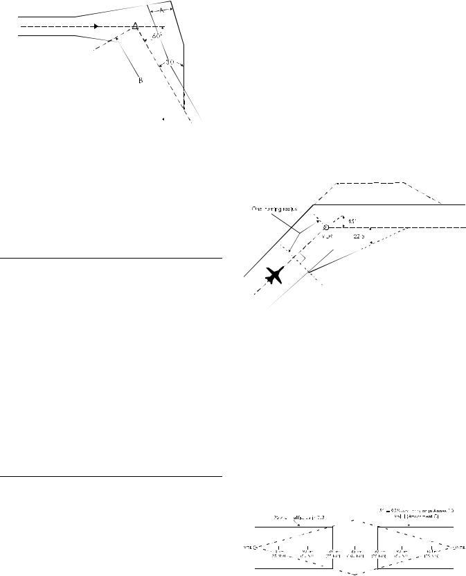
Attachment A |
Annex 11 — Air Traffic Services |
Figure A-4
3.10 The following table outlines the distances to be used in sample cases when providing additional protected airspace for route segments at and below FL 450, intersecting at a VOR or meeting at a VOR intersection not more than 139 km (75 NM) from each VOR.
Note.— Refer to Figures A-3 and A-4.
Angle of |
|
|
|
|
|
intersection |
30° |
45° |
60° |
75° |
90° |
|
|
|
|
|
|
VOR |
|
|
|
|
|
*Distance “A” (km) |
5 |
9 |
13 |
17 |
21 |
(NM) |
3 |
5 |
7 |
9 |
11 |
*Distance “B” (km) |
46 |
62 |
73 |
86 |
92 |
(NM) |
25 |
34 |
40 |
46 |
50 |
Intersection |
|
|
|
|
|
*Distance “A” (km) |
7 |
11 |
17 |
23 |
29 |
(NM) |
4 |
6 |
9 |
13 |
16 |
*Distance “B” (km) |
66 |
76 |
88 |
103 |
111 |
(NM) |
36 |
41 |
48 |
56 |
60 |
*Distances are rounded up to the next whole kilometre/nautical mile.
Note.— For behaviour of aircraft at turns, see Circular 120,
4.4.
3.11 Figure A-5 illustrates a method to construct the required additional protected airspace on the inside of turns for turns of 90 degrees or less:
Locate a point on the airway centre line, equal to the radius of turn plus the along-track tolerance prior to the nominal turning point.
From this point, drop a perpendicular line to intersect the edge of the airway on the inside of the turn.
From this point on the inner edge of the airway, construct a line to intersect the airway centre line beyond the turn at an angle of half of the angle of turn.
The resulting triangle on the inside of the turn depicts the additional airspace which should be protected for the change of direction. For any turn of 90 degrees or less, the extra space on the inside will serve for aircraft approaching the turn from either direction.
Note 1.— Criteria for the calculation of the along-track tolerance are contained in PANS-OPS (Doc 8168), Volume II, Part III, Appendix to Chapter 31.
Note 2.— Guidance on the calculation of radius of turn is provided in Section 7.
Figure A-5
3.12For turns at VOR intersections, the principles of construction for extra airspace on the inside of a turn as described in 3.11 can be applied. Depending on the distance of the intersection from one or both VORs, one or both airways may have a splay at the intersection. Depending upon the situation, the extra airspace may be inside, partially inside, or outside of the 95 per cent containment. If the route is used in both directions, the construction should be completed separately for each direction.
3.13Measured data for routes longer than 278 km (150 NM) between VORs are not yet available. To determine protected airspace beyond 139 km (75 NM) from the VOR, the use of an angular value of the order of 5 degrees as representing the probable system performance would appear satisfactory. The following figure illustrates this application.
Figure A-6
ATT A-3 |
1/11/01 |
--`,,```,,,,````-`-`,,`,,`,`,,`---
Copyright International Civil Aviation Organization |
|
Provided by IHS under license with ICAO |
|
No reproduction or networking permitted without license from IHS |
Not for Resale |
Annex 11 — Air Traffic Services
4. Spacing of parallel routes defined by VORs
Note.— The material of this section has been derived from measured data using the collision-risk/target level of safety method.
4.1 The collision risk calculation, performed with the data of the European study mentioned in 1.1 indicates that, in the type of environment investigated, the distance between route centre lines (S in Figure A-7) for distances between VORs of 278 km (150 NM) or less should normally be a minimum of:
a)33.3 km (18 NM) for parallel routes where the aircraft on the routes fly in opposite direction; and
b)30.6 km (16.5 NM) for parallel routes where the aircraft on the two routes fly in the same direction.
Figure A-7
Note.— Two route segments are considered parallel when:
—they have about the same orientation, i.e. the angular difference does not exceed 10 degrees;
—they are not intersecting, i.e. another form of separation must exist at a defined distance from the intersection;
—traffic on each route is independent of traffic on the other route, i.e. it does not lead to restrictions on the other route.
4.2This spacing of parallel routes assumes:
a)aircraft may either during climb or descent or during level flight be at the same flight levels on the two routes;
b)traffic densities of 25 000 to 50 000 flights per busy two-month period;
c)VOR transmissions which are regularly flight checked in accordance with Doc 8071 — Manual on Testing of Radio Navigation Aids, Volume I, and have been found
Attachment A
to be satisfactory in accordance with the procedures in that document for navigational purposes on the defined routes; and
d)no real-time radar or ADS-B monitoring or control of the lateral deviations is exercised.
4.3 Preliminary work indicates that, in the circumstances described in a) to c) below, it may be possible to reduce the minimum distance between routes. However, the figures given have not been precisely calculated and in each case a detailed study of the particular circumstances is essential:
a)if the aircraft on adjacent routes are not assigned the same flight levels, the distance between the routes may be reduced; the magnitude of the reduction will depend on the vertical separation between aircraft on the adjacent tracks and on the percentage of climbing and descending traffic, but is not likely to be more than
5.6km (3 NM);
b)if the traffic characteristics differ significantly from those contained in Circular 120, the minima contained in
4.1may require adjustment. For example, for traffic densities of about 10 000 flights per busy two-month period a reduction of 900 to 1 850 m (0.5 to 1.0 NM) may be possible;
c)the relative locations of the VORs defining the two tracks and the distance between the VORs will have an effect on the spacing, but this has not been quantified.
4.4 Application of radar or ADS-B monitoring and control of the lateral deviations of the aircraft may have a large effect on the minimum allowable distance between routes. Studies on the effect of radar monitoring indicate that:
— further work is necessary before a fully satisfactory mathematical model can be developed;
— any reduction of separation is closely related to:
— traffic (volume, characteristics);
— coverage and data processing, availability of an
automatic alarm; |
--- |
— sector workload; and |
`,,`,,`,`,,`-` |
— monitoring continuity; |
|
— radiotelephony quality. |
- |
According to these studies and taking into account the |
--`,,```,,,,```` |
experience some States have accumulated over many years |
|
with parallel route systems under continuous radar control, it |
|
can be expected that a reduction to the order of 15 to 18.5 km |
|
(8 to 10 NM), but most probably not less than 13 km (7 NM), |
|
may be possible as long as radar monitoring workload is not |
|
increased substantially by that reduction. Actual operations of |
|
such systems using reduced lateral spacing have shown that: |
|
—it is very important to define and publish change-over points (see also 6);
22/11/07 |
ATT A-4 |
1/11/01 |
No. 45
Copyright International Civil Aviation Organization |
|
Provided by IHS under license with ICAO |
|
No reproduction or networking permitted without license from IHS |
Not for Resale |

Attachment A
—large turns should be avoided when possible; and
—where large turns cannot be avoided, required turn
profiles should be defined for turns larger than 20 degrees.
Even where the probability of total radar or ADS-B failure is very small, procedures to cover that case should be considered.
5. Spacing of adjacent VOR-defined routes that are not parallel
Note 1.— The material of this section is intended to provide guidance for situations where non-intersecting VOR-defined routes are adjacent and have an angular difference exceeding 10 degrees.
Note 2.— The material of this section has not been derived by means of the collision-risk/target level of safety method.
5.1For adjacent non-intersecting VOR-defined routes that are not parallel, the collision-risk/target level of safety method is not, at its present state of development, fully appropriate. For this reason use should be made of the material in 3.
5.2The protected airspace between such routes should not be less than that which will provide, without overlap, the
99.5per cent containment values given in the table in 3.4 (see example in Figure A-8).
5.3Where there is an angular difference of more than 25 degrees between route segments, additional protected airspace, as indicated in 3.5 to 3.10, should be provided.
Annex 11 — Air Traffic Services
6.Change-over points for VORs
6.1When considering the establishment of points for changeover from one VOR to another for primary navigational guidance on VOR-defined ATS routes, States should bear in mind that:
a)the establishment of change-over points should be made on the basis of performance of the VOR stations concerned, including an evaluation of the interference protection criteria. The process should be verified by flight checking (see Doc 8071, Volume I, Part II);
b)where frequency protection is critical, flight inspection should be undertaken at the highest altitudes to which the facility is protected.
6.2 Nothing in 6.1 should be interpreted as placing a restriction on the service ranges of VOR installations meeting the specifications in Annex 10, Volume I, 3.3.
7.Calculation of radius of turn
7.1The method used to calculate turn radii and the turn radii indicated below are applicable to aircraft performing a constant radius turn. The material has been derived from the turn performance criteria developed for RNP 1 ATS routes and can be used in the construction of the required additional protected airspace on the inside of turns also for ATS routes other than those defined by VOR.
7.2Turn performance is dependent on two parameters — ground speed and bank angle. Due to the effect of the wind component changing with the change of heading, the ground speed and hence bank angle will change during a constant radius turn. However, for turns not greater than approximately 90 degrees and for the speed values considered below, the following formula can be used to calculate the achievable constant radius of turn, where the ground speed is the sum of the true airspeed and the wind speed:
Radius of turn = |
(Ground speed)2 |
|
Constant ‘G’ * TAN(bank angle) |
|
7.3 The greater the ground speed, the greater will be the |
|
|
required bank angle. To ensure that the turn radius is represen- |
|
|
tative for all foreseeable conditions, it is necessary to consider |
|
|
extreme parameters. A true airspeed of 1 020 km/h (550 kt) is |
|
|
considered probably the greatest to be encountered in the |
|
|
upper levels. Combined with maximum anticipated wind |
|
|
speeds in the medium and upper flight levels of 370 km/h |
|
|
(200 |
kt) [99.5 per cent values based on meteorological data], |
|
a maximum ground speed of 1 400 km/h (750 kt) should be |
|
|
considered. Maximum bank angle is very much a function of |
|
|
individual aircraft. Aircraft with high wing loadings flying at |
|
|
or near their maximum flight level are highly intolerant of |
|
Figure A-8 |
extreme angles. Most transport aircraft are certified to fly no |
|
|
ATT A-5 |
22/11/07 |
|
1/11/01 |
|
|
|
No. 45 |
--`,,```,,,,````-`-`,,`,,`,`,,`---
Copyright International Civil Aviation Organization |
|
Provided by IHS under license with ICAO |
|
No reproduction or networking permitted without license from IHS |
Not for Resale |

|
Annex 11 — Air Traffic Services |
|
|
slower than 1.3 times their stall speed for any given |
|
|
configuration. Because the stall speed rises with TAN(bank |
|
|
angle), many operators try not to cruise below 1.4 times the |
|
-- |
stall speed to protect against gusts or turbulence. For the same |
|
reason, many transport aircraft fly at reduced maximum angles |
||
-`-`,,```,,,,```` |
||
highest bank angle which can be tolerated by all aircraft types |
||
---`,,`,,`,`,,` |
of bank in cruise conditions. Hence, it can be assumed that the |
|
is in the order of 20 degrees. |
||
|
||
|
7.4 By calculation, the radius of turn of an aircraft flying |
|
|
at 1 400 km/h (750 kt) ground speed, with a bank angle of |
|
|
20 degrees, is 22.51 NM (41.69 km). For purposes of |
|
|
expediency, this has been reduced to 22.5 NM (41.6 km). |
|
|
Following the same logic for the lower airspace, it is |
|
|
considered that up to FL 200 (6 100 m) the maximum figures |
Attachment A
to be encountered are a true airspeed of 740 km/h (400 kt), with a tailwind of 370 km/h (200 kt). Keeping the maximum bank angle of 20 degrees, and following the same formula, the turn would be defined along a radius of 14.45 NM (26.76 km). For expediency, this figure may be rounded up to 15 NM (27.8 km).
7.5 Given the above, the most logical break point between the two ground speed conditions is between FL 190 (5 800 m) and FL 200 (6 100 m). In order to encompass the range of turn anticipation algorithms used in current flight management systems (FMS) under all foreseeable conditions, the turn radius at FL 200 and above should be defined as 22.5 NM (41.6 km) and at FL 190 and below as 15 NM (27.8 km).
1/11/01 |
ATT A-6 |
Copyright International Civil Aviation Organization |
|
Provided by IHS under license with ICAO |
|
No reproduction or networking permitted without license from IHS |
Not for Resale |

ATTACHMENT B. METHOD OF ESTABLISHING ATS ROUTES
FOR USE BY RNAV-EQUIPPED AIRCRAFT
(Paragraph 2.7.1 and Section 2.12 refer)
1. Introduction
1.1 This guidance material is the result of studies carried
out in several States. It also reflects the long existence of |
|
-- |
contained herein have not been derived by means of |
the values`-`,,```,,,,```` |
|
RNAV criteria in several States. It must be noted that some of
the collision- -risk/target level of safety method. This is indicated where`,,`,,`,`,,` applicable. ---
1.2 States are encouraged to keep ICAO fully informed of the results of their application of the provisions of this guidance material.
to or better than a track-keeping accuracy of ±11.1 km (6 NM) for 99.5 per cent of the flight time of all aircraft using RNAV equipment. Navigational performance of this type is expected to be consistent with a track-keeping accuracy of ±7.4 km (4 NM) for 95 per cent of flight time of all aircraft using RNAV equipment. This level is similar to that currently achieved by aircraft without RNAV capability operating on existing routes defined by VOR or VOR/DME, where the VORs are less than 93 km (50 NM) apart.
2.2 Protected airspace for RNAV ATS routes based on RNP 4
2. Operational applications of RNAV routes based on RNP 4
2.1General
2.1.1This guidance material is meant for use on RNAV routes that are established within the coverage area of electronic navigation aids that will provide necessary updates and guard against RNAV “blunder” errors.
2.1.2Only those aircraft that have been granted airworthiness/operational approval in accordance with Sections 5.5 and 5.6, Manual on Required Navigation Performance (RNP)
(Doc 9613) are to be afforded air traffic services on RNAV routes developed in accordance with this material.
2.1.3The use of RNAV equipment should be permitted for navigation along ATS routes defined by VOR. Additionally, RNAV routes may be provided where practicable and when justified by the number of aircraft with RNAV capability. The routes may be:
a)fixed RNAV routes;
b)contingency RNAV routes; and
c)random RNAV routings.
2.1.4 The navigational performance required of such RNAV equipment envisages a level of navigational accuracy for en-route purposes having a navigation performance equal
2.2.1 The minimum protected airspace provided for RNAV ATS routes should be 11.1 km (6 NM) either side of the intended track, within which RNAV-equipped aircraft can be expected to remain for 99.5 per cent of the flight time. Before applying the values stemming from this concept, account should be taken of any practical experience gained in the airspace under consideration as well as the possibility of achieving improvements in the overall navigation performance of aircraft. In this context, when lateral deviations are being controlled with the aid of radar monitoring, the size of the protected airspace required may be reduced in accordance with the following:
|
|
Percentage containment |
|
|
||
|
95 |
96 |
97 |
98 |
99 |
99.5 |
|
|
|
|
|
|
|
km |
±7.4 |
±7.4 |
±8.3 |
±9.3 |
±10.2 |
±11.1 |
NM |
±4.0 |
±4.0 |
±4.5 |
±5.0 |
±5.5 |
±6.0 |
|
|
|
|
|
|
|
2.2.2 Radar monitoring studies indicate that any potential reduction of the protected airspace is closely related to traffic characteristics, information available to the controller, and sector workload. Finally, it is worth considering that the analysis of RNAV accuracy performed in terms of containment measurements by some European States has shown that flights with RNAV capability were within 5 NM of the route centre line for 99.5 per cent of the time (EUR Doc 001, RNAV/4 refers). If the appropriate ATS authority considers that more protection is required, e.g. because of proximity of prohibited,
ANNEX 11 |
ATT B-1 |
22/11/071/1 /01 |
|
|
|
28/ |
1/02 |
|
|
No..4541 |
|
Copyright International Civil Aviation Organization |
|
Provided by IHS under license with ICAO |
|
No reproduction or networking permitted without license from IHS |
Not for Resale |
Annex 11 — Air Traffic Services
restricted or danger areas, climb and descent paths of military aircraft, etc., additional buffers should be provided.
2.2.3 Where there is an angular difference of more than 25 degrees between route segments, additional protected airspace, as indicated in Attachment A, 3.5 to 3.12 and Section 7, should be provided.
Note.— Different levels of navigation accuracy may be required by States for operations of RNAV-equipped aircraft. These requirements are not covered by this guidance material and may necessitate changes to protected airspace criteria.
2.3Spacing between parallel RNAV routes
based on RNP 4
When utilizing protected airspace as described in 2.2, route centre lines may be spaced such that the protected airspaces encompassing the 99.5 per cent containment values do not overlap. When implementing a spacing encompassing less than the 99.5 per cent containment values, radar monitoring is required.
3. Spacing between parallel tracks or between parallel RNAV route centre lines based on RNP type
3.1It should be noted that, where indicated, the spacings depicted below are based on safety assessments performed specifically for a particular network of tracks or routes. As such, the assessments evaluated traffic characteristics which might be unique to the network being assessed. For example, some of these characteristics are traffic density, the frequency of aircraft passing with minimum separation, communication and surveillance facilities, etc. Additional information on performing safety assessments is contained in the Manual on Airspace Planning Methodology for the Determination of Separation Minima (Doc 9689).
3.2When determining the spacing between parallel tracks or ATS routes (hereinafter referred to as a “system”), the safety assessment, involving an examination of items such as those listed in 3.1 above, should be performed against a minimum acceptable safety level.
3.2.1Where “fatal accidents per flight hour” is considered
to be an appropriate metric, a target level of safety (TLS) of 5 × 10⁻⁹ fatal accidents per flight hour per dimension should be applied for determining the acceptability of future en-route
systems that will be implemented after the year 2000. Until then, a TLS of 2 × 10⁻⁸ fatal accidents per flight hour per dimension may be applied for this purpose.
3.2.2However, where “fatal accidents per flight hour” is not considered to be an appropriate metric, justifiable alternative metrics and methods of assessment providing an
Attachment B
acceptable level of safety may be established by States and, as appropriate, be implemented by regional agreements.
3.3If, at the time a system is established or upon a subsequent system safety assessment, it is determined that the system does not meet the appropriate level of safety for the method of assessment being used, a reassessment should be considered. This assessment should be undertaken in accordance with Doc 9689 to determine if a level of safety equivalent to or better than the minimum acceptable level can be met.
3.4Examples of spacings for systems in specific areas or regions based on RNP type are provided below. Where these spacings are based on the characteristics of a specific area or region (reference system), other States or regions will need to evaluate their own systems for comparability with the reference system.
3.4.1 For procedural environments:
a)RNP 20
Spacing: 185 km (100 NM);
Basis: Existing usage, based on long-standing, operational experience; and
Minimum ATS requirements:
NAV — All aircraft need RNP type 20 approval appropriate for the routes/tracks to be flown
COM — Voice communications through a third party SUR — Procedural-pilot position reports.
b)RNP 12.6
Spacing: 110 km (60 NM);
Basis: Collision risk model performed for NAT Organized Track Structure (Report of the Limited/North Atlantic Regional Air Navigation Meeting (1976)
(Doc 9182)); and
Minimum ATS requirements:
NAV — All aircraft need RNP type 12.6 approval appropriate for the routes/tracks to be flown
COM — Voice communications through a third party
SUR — Procedural-pilot position reports
Other — System safety must be evaluated periodically.
Note.— Direct controller/pilot communications may be desirable in certain areas, such as areas of known convective weather.
1/11/01 |
ATT B-2 |
28/11/02 |
|
No. 41
--`,,```,,,,````-`-`,,`,,`,`,,`---
Copyright International Civil Aviation Organization |
|
Provided by IHS under license with ICAO |
|
No reproduction or networking permitted without license from IHS |
Not for Resale |
Attachment B
-- |
c) |
RNP 10 |
|
-`-`,,```,,,,```` |
|||
|
Spacing: 93 km (50 NM); |
||
`,,`,,`,`,,` |
|
Basis: Collision risk model performed by the United |
|
--- |
|
States Federal Aviation Administration for the Pacific |
|
|
|
||
|
|
Region based on North Pacific traffic characteristics; |
|
|
|
and |
|
|
|
Minimum ATS requirements: |
|
|
|
NAV — All aircraft need RNP type 10 approval |
|
|
|
appropriate for the routes/tracks to be flown |
|
|
|
COM — Voice communications through a third party |
|
|
|
SUR — Procedural-pilot position reports |
|
|
|
Other — System safety must be evaluated periodically. |
|
|
|
Note.— Direct controller/pilot communications may |
|
|
|
be desirable in certain areas, such as areas of known |
|
|
|
convective weather. |
|
|
d) |
RNP 5 (or RNP 4 or better) |
|
|
|
Spacing: 30.6 km (16.5 NM) in a unidirectional system |
|
|
|
33.3 km (18 NM) in a bi-directional system; |
|
|
|
Basis: Comparison to a high-density continental |
|
|
|
reference system (VOR spacing) as described in |
|
|
|
Attachment A; and |
|
|
|
Minimum ATS requirements: |
|
|
|
NAV — All aircraft need RNP type 5 approval |
|
|
|
appropriate for the routes/tracks to be flown, and the |
|
|
|
NAVAID infrastructure must be provided sufficient to |
|
|
|
support RNP 5 operations |
|
|
|
COM — Direct VHF controller/pilot voice communi- |
|
|
|
cations |
|
|
|
SUR — Procedural-pilot position reports. |
|
|
|
Note 1.— Guidance material relating to the use of |
|
|
|
RNP 5 is contained in the Manual on Required |
|
|
|
Navigation Performance (RNP) (Doc 9613). |
|
|
|
Note 2.— This spacing was not developed for |
|
|
|
applicability in remote and/or oceanic airspace where |
|
|
|
an appropriate VOR infrastructure is not available. |
|
|
e) |
RNP 4 |
|
|
|
Spacing: 55.5 km (30 NM); |
|
|
|
Basis 1: Safety assessment performed by the United |
|
|
|
States Federal Aviation Administration based on analysis |
Annex 11 — Air Traffic Services
of acceptable rate of gross lateral errors in a parallel route system using 55.5 km (30 NM) track spacing while meeting a target level of safety of 5 × 10⁻⁹ fatal accidents per flight hour.
Basis 2: Minimum requirements for communications and surveillance listed below are operationally necessary to manage contingency and emergency events in a 55.5 km (30 NM) route system.
Note.— Further information on the safety assessment performed is contained in the Manual on Airspace Planning Methodology for the Determination of Separation Minima (Doc 9689).
Minimum ATS requirements:
NAV — RNP 4 shall be prescribed for the designated area, tracks or ATS routes
COM — Direct controller-pilot voice communications or controller-pilot data link communications (CPDLC)
SUR — An ADS-C system in which an event contract must be set that includes a lateral deviation event report whenever a deviation from track centre line greater than 9.3 km (5 NM) occurs.
Other — Prior to implementation, a system verification of sufficient duration and integrity shall be performed to demonstrate that the maximum acceptable rate of lateral deviations greater than or equal to 27.8 km (15 NM) will not exceed those listed in Table B-1 and that the system meets operational and technical requirements. The verification should be conducted after the minimum navigation, communications and surveillance requirements listed above have been met. Following implementation, a monitoring programme must be established to periodically verify that the system’s actual rate of lateral deviations greater than or equal to 27.8 km (15 NM) does not exceed the maximum prescribed in Table B-1 (information pertaining to monitoring can be found in the
Manual on Airspace Planning Methodology for the Determination of Separation Minima (Doc 9689), Chapter 8.
Note 1.— The airspace planner should first decide which of the four system descriptions applies in the airspace under consideration. If the system is not identical to one of the four cases described in Table B-1, the planner should conservatively interpolate between the cases by taking from the two cases that resemble the system, the one with the lower lateral deviation rate. Next, select from the first column, the value of system lateral occupancy that the system is not expected to exceed over the planning horizon. By reading the table at the row and column selected, the airspace planner obtains the value of the lateral deviation rate that should not be exceeded in the system to meet the TLS of 5 × 10⁻⁹ fatal accidents per flight hour.
ATT B-3 |
22/11/071/1 /01 |
|
|
28/ |
1/02 |
|
No..4541 |
|
Copyright International Civil Aviation Organization |
|
Provided by IHS under license with ICAO |
|
No reproduction or networking permitted without license from IHS |
Not for Resale |
Annex 11 — Air Traffic Services
Note 2.— Lateral deviations that should be considered for the purposes of assessing the system safety are any deviation from track of a magnitude greater than or equal to 27.8 km (15 NM) which are not associated with the execution of an approved contingency procedure.
Note 3.— Procedures pertaining to the use of ADS-C and CPDLC are contained in the PANS-ATM (Doc 4444), Chapters 13 and 14, respectively. Criteria for CPDLC and ADS-C should be established by an appropriate safety assessment. Information on safety assessments is contained in the Manual on Airspace Planning Methodology for the Determination of Separation Minima (Doc 9689).
Note 4.— This spacing was developed for applicability in remote and/or oceanic airspace where an appropriate VOR infrastructure is not available.
Note 5.— In this material, lateral occupancy means a number equal to twice the number of laterally proximate pairs of aircraft divided by the total number of aircraft. A detailed explanation of the terms used in collision risk modelling is contained in the Air Traffic Services Planning Manual
(Doc 9426), Part II, Chapter 4, Appendices A and C.
3.4.2 For radar environments:
a)RNP 4
Spacing: 14.8-22.2 km (8-12 NM);
Basis: Comparison to a reference system — containment areas, determined in accordance with 2.2.1, do not overlap; and
Attachment B
Minimum ATS requirements:
NAV — All aircraft need at least RNP type 4 approval appropriate for the routes/tracks to be flown, and the NAVAID infrastructure must be provided sufficient to support RNP 4 operations
COM — Direct VHF controller/pilot voice communications
SUR — Radar which meets existing standards
Other — System safety, including controller workload, must be evaluated.
b)RNP 5
Spacing: 18.5-27.8 km (10-15 NM);
Basis: Comparison to a reference system — containment areas, adapted from the provisions of 2.2.1 above to reflect RNP 5, do not overlap; and
Minimum ATS requirements:
NAV — All aircraft need at least RNP type 5 appropriate for the routes/tracks to be flown, and the NAVAID infrastructure must be provided sufficient to support RNP 5 operations
COM — Direct VHF controller/pilot voice communications
SUR — Radar which meets existing standards
Other — System safety, including controller workload, must be evaluated.
--`,,```,,,,````-`-`,,`,,`,`,,`---
1/11/01 |
ATT B-4 |
22/11/078 |
|
No. 451 |
|
Copyright International Civil Aviation Organization |
|
Provided by IHS under license with ICAO |
|
No reproduction or networking permitted without license from IHS |
Not for Resale |

|
Attachment B |
|
|
|
|
Annex 11 — Air Traffic Services |
|
|
|
Table B-1. Maximum acceptable rates of lateral deviations |
|
||||
|
|
greater than or equal to 27.8 km (15 NM) |
|
||||
|
|
|
|
|
|
|
|
|
Maximum expected |
|
|
|
|
|
|
|
route system lateral |
Rate for two |
|
Rate for four |
|
Rate for seven |
Rate for two |
|
occupancy |
same-direction routes |
|
same-direction routes |
same-direction routes |
opposite-direction routes |
|
|
|
|
|
|
|
|
|
|
0.1 |
1.99 × 10⁻⁴ |
|
1.75 × 10⁻⁴ |
1.52 × 10⁻⁴ |
3.14 × 10⁻⁵ |
|
|
0.2 |
1.06 × 10⁻⁴ |
|
9.39 × 10⁻⁵ |
8.27 × 10⁻⁵ |
2.23 × 10⁻⁵ |
|
|
0.3 |
7.50 × 10⁻⁵ |
|
6.70 × 10⁻⁵ |
5.95 × 10⁻⁵ |
1.92 × 10⁻⁵ |
|
|
0.4 |
5.95 × 10⁻⁵ |
|
5.35 × 10⁻⁵ |
4.79 × 10⁻⁵ |
1.77 × 10⁻⁵ |
|
|
0.5 |
5.03 × 10⁻⁵ |
|
4.55 × 10⁻⁵ |
4.10 × 10⁻⁵ |
1.68 × 10⁻⁵ |
|
|
0.6 |
4.41 × 10⁻⁵ |
|
4.01 × 10⁻⁵ |
3.64 × 10⁻⁵ |
1.62 × 10⁻⁵ |
|
|
0.7 |
3.97 × 10⁻⁵ |
|
3.62 × 10⁻⁵ |
3.30 × 10⁻⁵ |
1.58 × 10⁻⁵ |
|
|
0.8 |
3.64 × 10⁻⁵ |
|
3.34 × 10⁻⁵ |
3.06 × 10⁻⁵ |
1.55 × 10⁻⁵ |
|
|
0.9 |
3.38 × 10⁻⁵ |
|
3.11 × 10⁻⁵ |
2.86 × 10⁻⁵ |
1.52 × 10⁻⁵ |
|
|
1.0 |
3.17 × 10⁻⁵ |
|
2.93 × 10⁻⁵ |
2.71 × 10⁻⁵ |
1.50 × 10⁻⁵ |
|
|
1.1 |
3.00 × 10⁻⁵ |
|
2.79 × 10⁻⁵ |
2.58 × 10⁻⁵ |
1.48 × 10⁻⁵ |
|
|
1.2 |
2.86 × 10⁻⁵ |
|
2.66 × 10⁻⁵ |
2.48 × 10⁻⁵ |
1.47 × 10⁻⁵ |
|
|
1.3 |
2.74 × 10⁻⁵ |
|
2.56 × 10⁻⁵ |
2.39 × 10⁻⁵ |
1.46 × 10⁻⁵ |
|
|
1.4 |
2.64 × 10⁻⁵ |
|
2.47 × 10⁻⁵ |
2.31 × 10⁻⁵ |
1.45 × 10⁻⁵ |
|
|
1.5 |
2.55 × 10⁻⁵ |
|
2.39 × 10⁻⁵ |
2.25 × 10⁻⁵ |
1.44 × 10⁻⁵ |
|
-- |
1.6 |
2.48 × 10⁻⁵ |
|
2.33 × 10⁻⁵ |
2.19 × 10⁻⁵ |
1.43 × 10⁻⁵ |
|
-`-`,,```,,,,```` |
|
|
|
|
|
|
|
1.7 |
2.41 × 10⁻⁵ |
|
2.27 × 10⁻⁵ |
2.14 × 10⁻⁵ |
1.42 × 10⁻⁵ |
||
|
|
||||||
---`,,`,,`,`,,` |
1.8 |
2.35 × 10⁻⁵ |
|
2.22 × 10⁻⁵ |
2.09 × 10⁻⁵ |
1.42 × 10⁻⁵ |
|
1.9 |
2.29 × 10⁻⁵ |
|
2.17 × 10⁻⁵ |
2.05 × 10⁻⁵ |
1.41 × 10⁻⁵ |
||
|
2.0 |
2.24 × 10⁻⁵ |
|
2.13 × 10⁻⁵ |
2.01 × 10⁻⁵ |
1.41 × 10⁻⁵ |
|
|
|
|
|
|
|
|
|
ATT B-5 |
1/11/01 |
|
|
28/ |
1/02 |
No. 41
Copyright International Civil Aviation Organization |
|
Provided by IHS under license with ICAO |
|
No reproduction or networking permitted without license from IHS |
Not for Resale |
ATTACHMENT C. TRAFFIC INFORMATION BROADCASTS BY AIRCRAFT (TIBA) AND RELATED OPERATING PROCEDURES
(See Chapter 4, 4.2.2, Note 2)
1. Introduction and applicability of broadcasts
1.1Traffic information broadcasts by aircraft are intended to permit reports and relevant supplementary information of an advisory nature to be transmitted by pilots on a designated VHF radiotelephone (RTF) frequency for the information of pilots of other aircraft in the vicinity.
1.2TIBAs should be introduced only when necessary and as a temporary measure.
1.3The broadcast procedures should be applied in designated airspace where:
the case of temporary disruption occurring in controlled airspace, the States responsible may promulgate, as the VHF RTF frequency to be used within the limits of that airspace, a frequency used normally for the provision of air traffic control service within that airspace.
2.1.2 Where VHF is used for air-ground communications with ATS and an aircraft has only two serviceable VHF sets, one should be tuned to the appropriate ATS frequency and the other to the TIBA frequency.
2.2Listening watch
|
a) there is a need to supplement collision hazard infor- |
A listening watch should be maintained on the TIBA |
||||||
|
mation provided by air traffic services outside controlled |
frequency 10 minutes before entering the designated airspace |
||||||
-- |
airspace; or |
|
|
|
until leaving this airspace. For an aircraft taking off from an |
|||
-`-`,,```,,,,```` |
b) there is a temporary disruption of normal |
air |
traffic |
aerodrome located within the lateral limits of the designated |
||||
airspace listening watch should start as soon as appropriate |
||||||||
services. |
|
|
|
after take-off and be maintained until leaving the airspace. |
||||
`,,`,,`,`,,` |
1.4 |
Such airspaces should be identified by |
the |
States |
|
|
||
--- |
|
|
|
|
|
|
|
|
responsible for provision of air traffic services within these |
|
|
||||||
airspaces, if necessary with the assistance of the appropriate |
|
2.3 Time of broadcasts |
||||||
ICAO Regional Office(s), and duly promulgated in aero- |
|
|
||||||
nautical information publications or NOTAM, together with |
A broadcast should be made: |
|||||||
the VHF RTF frequency, the message formats and the |
||||||||
|
|
|||||||
procedures to be used. Where, in the case of 1.3 a), more than |
a) |
10 minutes before entering the designated airspace or, |
||||||
one State is involved, the airspace should be designated on the |
||||||||
|
for a pilot taking off from an aerodrome located within |
|||||||
basis of regional air navigation agreements and promulgated |
|
|||||||
|
the lateral limits of the designated airspace, as soon as |
|||||||
in Doc 7030. |
|
|
|
|
||||
|
|
|
|
appropriate after take-off; |
||||
|
|
|
|
|
|
|
||
|
1.5 When establishing a designated airspace, dates for the |
b) |
10 minutes prior to crossing a reporting point; |
|||||
review of its applicability at intervals not exceeding 12 months |
||||||||
|
|
|||||||
should be agreed by the appropriate ATS authority(ies). |
|
c) |
10 minutes prior to crossing or joining an ATS route; |
|||||
|
|
|
|
|
|
|||
|
|
|
|
|
|
d) at 20-minute intervals between distant reporting points; |
||
|
|
2. |
Details of broadcasts |
|
|
e) |
2 to 5 minutes, where possible, before a change in flight |
|
|
|
|
|
|
|
|||
|
|
|
|
|
|
|
level; |
|
|
|
2.1 VHF RTF frequency to be used |
|
|
f) |
at the time of a change in flight level; and |
||
|
2.1.1 |
The VHF |
RTF frequency to be used |
should be |
||||
|
|
|
||||||
determined and promulgated on a regional basis. However, in |
g) at any other time considered necessary by the pilot. |
|||||||
ANNEX 11 |
|
|
ATT C-1 |
1/11/01 |
||||
Copyright International Civil Aviation Organization |
|
Provided by IHS under license with ICAO |
|
No reproduction or networking permitted without license from IHS |
Not for Resale |

Annex 11 — Air Traffic Services
2.4Forms of broadcast
2.4.1The broadcasts other than those indicating changes in flight level, i.e. the broadcasts referred to in 2.3 a), b), c),
d)and g), should be in the following form:
ALL STATIONS (necessary to identify a traffic information broadcast)
(call sign)
FLIGHT LEVEL (number) (or CLIMBING* TO FLIGHT
LEVEL (number))
(direction)
(ATS route) (or DIRECT FROM (position) TO (position))
POSITION (position**) AT (time)
ESTIMATING (next reporting point, or the point of crossing or joining a designated ATS route) AT (time)
(call sign)
FLIGHT LEVEL (number)
(direction)
Fictitious example:
“ALL STATIONS WINDAR 671 FLIGHT LEVEL 350 NORTHWEST BOUND DIRECT FROM PUNTA SAGA TO PAMPA POSITION 5040 SOUTH 2010 EAST AT 2358 ESTIMATING CROSSING ROUTE LIMA THREE ONE AT 4930 SOUTH 1920 EAST AT 0012 WINDAR 671 FLIGHT LEVEL 350 NORTHWEST BOUND OUT”
2.4.2 Before a change in flight level, the broadcast (referred to in 2.3 e)) should be in the following form:
ALL STATIONS
(call sign)
(direction)
(ATS route) (or DIRECT FROM (position) TO (position))
LEAVING FLIGHT LEVEL (number) FOR FLIGHT LEVEL (number) AT (position and time)
*For the broadcast referred to in 2.3 a) in the case of an aircraft taking off from an aerodrome located within the lateral limits of the designated airspace.
**For broadcasts made when the aircraft is not near an ATS significant point, the position should be given as accurately as possible and in any case to the nearest 30 minutes of latitude and longitude.
Attachment C
2.4.3 Except as provided in 2.4.4, the broadcast at the time of a change in flight level (referred to in 2.3 f)) should be in the following form:
ALL STATIONS
(call sign) (direction)
(ATS route) (or DIRECT FROM (position) TO (position))
LEAVING FLIGHT LEVEL (number) NOW FOR FLIGHT
LEVEL (number)
followed by:
ALL STATIONS
(call sign)
MAINTAINING FLIGHT LEVEL (number)
2.4.4 Broadcasts reporting a temporary flight level change to avoid an imminent collision risk should be in the following form:
ALL STATIONS
(call sign)
LEAVING FLIGHT LEVEL (number) NOW FOR FLIGHT
LEVEL (number)
followed as soon as practicable by:
ALL STATIONS
(call sign)
RETURNING TO FLIGHT LEVEL (number) NOW
2.5 Acknowledgement
of the broadcasts
The broadcasts should not be acknowledged unless a potential collision risk is perceived.
3.Related operating procedures
3.1Changes of cruising level
3.1.1Cruising level changes should not be made within the designated airspace, unless considered necessary by pilots to avoid traffic conflicts, for weather avoidance or for other valid operational reasons.
1/11/01 |
ATT C-2 |
--`,,```,,,,````-`-`,,`,,`,`,,`---
Copyright International Civil Aviation Organization |
|
Provided by IHS under license with ICAO |
|
No reproduction or networking permitted without license from IHS |
Not for Resale |
Attachment C
3.1.2 When cruising level changes are unavoidable, all available aircraft lighting which would improve the visual detection of the aircraft should be displayed while changing levels.
3.2Collision avoidance
If, on receipt of a traffic information broadcast from another aircraft, a pilot decides that immediate action is necessary to avoid an imminent collision risk, and this cannot be achieved in accordance with the right-of-way provisions of Annex 2, the pilot should:
a) unless an alternative manoeuvre appears more appropriate, immediately descend 150 m (500 ft), or 300 m (1 000 ft) if above FL 290 in an area where a vertical separation minimum of 600 m (2 000 ft) is applied;
Annex 11 — Air Traffic Services
b)display all available aircraft lighting which would improve the visual detection of the aircraft;
c)as soon as possible, reply to the broadcast advising action being taken;
d)notify the action taken on the appropriate ATS frequency; and
e)as soon as practicable, resume normal flight level, notifying the action on the appropriate ATS frequency.
3.3 Normal position reporting procedures
Normal position reporting procedures should be continued at all times, regardless of any action taken to initiate or acknowledge a traffic information broadcast.
ATT C-3 |
27/11/03 |
1/11/01 |
|
--`,,```,,,,````-`-`,,`,,`,`,,`--- |
No. 42 |
Copyright International Civil Aviation Organization |
|
Provided by IHS under license with ICAO |
|
No reproduction or networking permitted without license from IHS |
Not for Resale |
ATTACHMENT D. MATERIAL RELATING TO CONTINGENCY PLANNING
(see 2.29)
1. Introduction |
2. Status of contingency plans |
1.1Guidelines for contingency measures for application in the event of disruptions of air traffic services and related supporting services were first approved by the Council on 27 June 1984 in response to Assembly Resolution A23-12, following a study by the Air Navigation Commission and consultation with States and international organizations concerned, as required by the Resolution. The guidelines were subsequently amended and amplified in the light of experience gained with the application of contingency measures in various parts of the world and in differing circumstances.
1.2The purpose of the guidelines is to assist in providing for the safe and orderly flow of international air traffic in the event of disruptions of air traffic services and related supporting services and in preserving the availability of major world air routes within the air transportation system in such circumstances.
1.3The guidelines have been developed in recognition of the fact that circumstances before and during events causing disruptions of services to international civil aviation vary widely and that contingency measures, including access to designated aerodromes for humanitarian reasons, in response to specific events and circumstances must be adapted to these circumstances. They set forth the allocation of responsibility among States and ICAO for the conduct of contingency planning and the measures to be taken into consideration in developing, applying and terminating the application of such plans.
1.4The guidelines are based on experience which has shown, inter alia, that the effects of disruption of services in particular portions of airspace are likely to affect significantly the services in adjacent airspace, thereby creating a requirement for international coordination, with the assistance of ICAO as appropriate. Hence, the role of ICAO in the field of contingency planning and coordination of such plans is described in the guidelines. They also reflect the experience that ICAO’s role in contingency planning must be global and not limited to airspace over the high seas and areas of undetermined sovereignty, if the availability of major world air routes within the air transportation system is to be preserved. Finally, they further reflect the fact that international organizations concerned, such as the International Air Transport Association (IATA) and the International Federation of Airline Pilots’ Associations (IFALPA), are valuable advisers on the practicability of overall plans and elements of such plans.
Contingency plans are intended to provide alternative facilities and services to those provided for in the regional air navigation plan when those facilities and services are temporarily not available. Contingency arrangements are therefore temporary in nature, remain in effect only until the services and facilities of the regional air navigation plan are reactivated and, accordingly, do not constitute amendments to the regional plan requiring processing in accordance with the “Procedure for the Amendment of Approved Regional Plans”. Instead, in cases where the contingency plan would temporarily deviate from the approved regional air navigation plan, such deviations are approved, as necessary, by the President of the ICAO Council on behalf of the Council.
3. Responsibility for developing, promulgating and implementing contingency plans
3.1The State(s) responsible for providing air traffic services and related supporting services in particular portions of airspace is (are) also responsible, in the event of disruption or potential disruption of these services, for instituting measures to ensure the safety of international civil aviation operations and, where possible, for making provisions for alternative facilities and services. To that end the State(s) should develop, promulgate and implement appropriate contingency plans. Such plans should be developed in consultation with other States and airspace users concerned and with ICAO, as appropriate, whenever the effects of the service disruption(s) are likely to affect the services in adjacent airspace.
3.2The responsibility for appropriate contingency action in respect of airspace over the high seas continues to rest with the State(s) normally responsible for providing the services until, and unless, that responsibility is temporarily reassigned by ICAO to (an)other State(s).
3.3Similarly, the responsibility for appropriate contingency action in respect of airspace where the responsibility for providing the services has been delegated by another State continues to rest with the State providing the services until, and unless, the delegating State terminates temporarily the delegation. Upon termination, the delegating State assumes responsibility for appropriate contingency action.
ANNEX 11 |
ATT D-1 |
23/11/06 |
|
|
No. 44 |
--`,,```,,,,````-`-`,,`,,`,`,,`---
Copyright International Civil Aviation Organization |
|
Provided by IHS under license with ICAO |
|
No reproduction or networking permitted without license from IHS |
Not for Resale |
Annex 11 — Air Traffic Services
3.4 ICAO will initiate and coordinate appropriate contingency action in the event of disruption of air traffic services and related supporting services affecting international civil aviation operations provided by a State wherein, for some reason, the authorities cannot adequately discharge the responsibility referred to in 3.1. In such circumstances, ICAO will work in coordination with States responsible for airspace adjacent to that affected by the disruption and in close consultation with international organizations concerned. ICAO will also initiate and coordinate appropriate contingency action at the request of States.
4. Preparatory action
4.1 Time is essential in contingency planning if hazards to air navigation are to be reasonably prevented. Timely introduc-
-- |
|
tion of contingency arrangements requires decisive initiative |
|
have,-`-`,,```,,,,```` |
as far as practicable, been completed and agreed among |
and action, which again presupposes that contingency plans |
|
the parties concerned before the occurrence of the event |
|
requiring`,,`,,`,`,,` |
contingency action, including the manner and timing |
of promulgating such arrangements. |
|
--- |
|
4.2 For the reasons given in 4.1, States should take preparatory action, as appropriate, for facilitating timely introduction of contingency arrangements. Such preparatory action should include:
a)preparation of general contingency plans for introduction in respect of generally foreseeable events such as industrial action or labour unrest affecting the provision of air traffic services and/or supporting services. In recognition of the fact that the world aviation community is not party to such disputes, States providing services in airspace over the high seas or of undetermined sovereignty should take appropriate action to ensure that adequate air traffic services will continue to be provided to international civil aviation operations in non-sovereign airspace. For the same reason, States providing air traffic services in their own airspace or, by delegation, in the airspace of (an)other State(s) should take appropriate action to ensure that adequate air traffic services will continue to be provided to international civil aviation operations concerned, which do not involve landing or take-off in the State(s) affected by industrial action;
b)assessment of risk to civil air traffic due to military conflict or acts of unlawful interference with civil aviation as well as a review of the likelihood and possible consequences of natural disasters. Preparatory action should include initial development of special contin-gency plans in respect of natural disasters, military conflicts or acts of unlawful interference with civil aviation that are likely to affect the availability of airspace for civil aircraft operations and/or the provision
of air traffic services and supporting services. It should
Attachment D
be recognized that avoidance of particular portions of airspace on short notice will require special efforts by States responsible for adjacent portions of airspace and by international aircraft operators with regard to planning of alternative routings and services, and the air traffic services authorities of States should therefore, as far as practicable, endeavour to anticipate the need for such alternative actions;
c)monitoring of any developments that might lead to events requiring contingency arrangements to be developed and applied. States should consider designating persons/ administrative units to undertake such monitoring and, when necessary, to initiate effective follow-up action; and
d)designation/establishment of a central agency which, in the event of disruption of air traffic services and introduction of contingency arrangements, would be able to provide, 24 hours a day, up-to-date information on the situation and associated contingency measures until the system has returned to normal. A coordinating team should be designated within, or in association with, such a central agency for the purpose of coordinating activities during the disruption.
4.3 ICAO will be available for monitoring developments that might lead to events requiring contingency arrangements to be developed and applied and will, as necessary, assist in the development and application of such arrangements. During the emergence of a potential crisis, a coordinating team will be established in the Regional Office(s) concerned and at ICAO Headquarters in Montreal, and arrangements will be made for competent staff to be available or reachable 24 hours a day. The tasks of these teams will be to monitor continuously information from all relevant sources, to arrange for the constant supply of relevant information received by the State aeronautical information service at the location of the Regional Office and Headquarters, to liaise with international organizations concerned and their regional organizations, as appropriate, and to exchange up-to-date information with States directly concerned and States which are potential participants in contingency arrangements. Upon analysis of all available data, authority for initiating the action considered necessary in the circumstances will be obtained from the State(s) concerned.
5.Coordination
5.1A contingency plan should be acceptable to providers and users of contingency services alike, i.e. in terms of the ability of the providers to discharge the functions assigned to them and in terms of safety of operations and traffic handling capacity provided by the plan in the circumstances.
5.2Accordingly, States which anticipate or experience disruption of air traffic services and/or related supporting
27/11/03 |
ATT D-2 |
31/10/03 |
No. 42 |
|
Corr. |
Copyright International Civil Aviation Organization |
|
Provided by IHS under license with ICAO |
|
No reproduction or networking permitted without license from IHS |
Not for Resale |
Attachment D
services should advise, as early as practicable, the ICAO Regional Office accredited to them, and other States whose services might be affected. Such advice should include information on associated contingency measures or a request for assistance in formulating contingency plans.
5.3Detailed coordination requirements should be determined by States and/or ICAO, as appropriate, keeping the above in mind. In the case of contingency arrangements not appreciably affecting airspace users or service provided outside the airspace of the (single) State involved, coordination requirements are naturally few or non-existent. Such cases are believed to be few.
5.4In the case of multi-State ventures, detailed coordination leading to formal agreement of the emerging contingency plan should be undertaken with each State which is to participate. Such detailed coordination should also be undertaken with those States whose services will be significantly affected, for example by re-routing of traffic, and with international organizations concerned who provide invaluable operational insight and experience.
5.5Whenever necessary to ensure orderly transition to contingency arrangements, the coordination referred to in this section should include agreement on a detailed, common NOTAM text to be promulgated at a commonly agreed effective date.
6. Development, promulgation and application of contingency plans
6.1 Development of a sound contingency plan is dependent upon circumstances, including the availability, or not, of the airspace affected by the disruptive circumstances for use by international civil aviation operations. Sovereign airspace can be used only on the initiative of, or with the agreement or consent of, the authorities of the State concerned regarding such use. Otherwise, the contingency arrangements
must involve bypassing the airspace and should be developed |
|||||
-- |
|
States. In the case of airspace over the high seas or of |
|||
adjacent-`,,```,,,,```` |
|||||
by adjacent States or by ICAO in cooperation with such |
|||||
undetermined |
sovereignty, |
development of |
the contingency |
||
- ` |
degree of |
erosion of |
the alternative |
services offered, |
|
the`,,`,,`,`,,`--- |
|||||
plan might involve, depending upon circumstances, including
temporary reassignment by ICAO of the responsibility for providing air traffic services in the airspace concerned.
6.2 Development of a contingency plan presupposes as much information as possible on current and alternative routes, navigational capability of aircraft and availability or partial availability of navigational guidance from ground-based aids, surveillance and communications capability of adjacent air traffic services units, volume and types of aircraft to be accommodated and the actual status of the air traffic services, communications, meteorological and aeronautical information
Annex 11 — Air Traffic Services
services. Following are the main elements to be considered for contingency planning depending upon circumstances:
a)re-routing of traffic to avoid the whole or part of the airspace concerned, normally involving establishment of additional routes or route segments with associated conditions for their use;
b)establishment of a simplified route network through the airspace concerned, if it is available, together with a flight level allocation scheme to ensure lateral and vertical separation, and a procedure for adjacent area control centres to establish longitudinal separation at the entry point and to maintain such separation through the airspace;
c)reassignment of responsibility for providing air traffic services in airspace over the high seas or in delegated airspace;
d)provision and operation of adequate air-ground communications, AFTN and ATS direct speech links, including reassignment, to adjacent States, of the responsibility for providing meteorological information and information on status of navigation aids;
e)special arrangements for collecting and disseminating in-flight and post-flight reports from aircraft;
f)a requirement for aircraft to maintain continuous listening watch on a specified pilot-pilot VHF frequency in specified areas where air-ground communications are uncertain or non-existent and to broadcast on that frequency, preferably in English, position information and estimates, including start and completion of climb and descent;
g)a requirement for all aircraft in specified areas to display navigation and anti-collision lights at all times;
h)a requirement and procedures for aircraft to maintain an increased longitudinal separation that may be established between aircraft at the same cruising level;
i)a requirement for climbing and descending well to the right of the centre line of specifically identified routes;
j)establishment of arrangements for controlled access to the contingency area to prevent overloading of the contingency system; and
k)a requirement for all operations in the contingency area to be conducted in accordance with IFR, including allocation of IFR flight levels, from the relevant Table of Cruising Levels in Appendix 3 of Annex 2, to ATS routes in the area.
6.3 Notification, by NOTAM, of anticipated or actual disruption of air traffic services and/or related supporting
ATT D-3 |
27/11/03 |
|
No. 42 |
Copyright International Civil Aviation Organization |
|
Provided by IHS under license with ICAO |
|
No reproduction or networking permitted without license from IHS |
Not for Resale |

Annex 11 — Air Traffic Services
services should be dispatched to users of air navigation services as early as practicable. The NOTAM should include the associated contingency arrangements. In the case of foreseeable disruption, the advance notice should in any case not be less than 48 hours.
Attachment D
6.4 Notification by NOTAM of discontinuance of contingency measures and reactivation of the services set forth in the regional air navigation plan should be dispatched as early as practicable to ensure an orderly transfer from contingency conditions to normal conditions.
--`,,```,,,,````-`-`,,`,,`,`,,`---
|
|
|
ATT D-4 |
273/11/036 |
|
||
|
No. 424 |
|
|
Copyright International Civil Aviation Organization |
|
Provided by IHS under license with ICAO |
|
No reproduction or networking permitted without license from IHS |
Not for Resale |
ATTACHMENT E. ACCEPTABLE LEVEL OF SAFETY
1. Introduction |
3. Implementation |
1.1The introduction of the concept of acceptable level of safety responds to the need to complement the prevailing approach to the management of safety based upon regulatory compliance, with a performance based approach that aims for continuous improvement to the overall level of safety.
1.2Acceptable level of safety expresses the safety goals of an oversight authority, an operator, or a services provider. From the perspective of the relationship between oversight authorities and operators/services providers, it provides the minimum safety objective(s) acceptable to the oversight authority to be achieved by the operators/services providers while conducting their core business functions. It is a reference against which the oversight authority can measure safety performance.
1.3Establishing acceptable level(s) of safety for the safety programme does not replace legal, regulatory, or other established requirements, nor does it relieve States from their obligations regarding the Convention on International Civil Aviation and its related provisions.
1.4Establishing acceptable level(s) of safety for the safety management system does not relieve operators/services providers from their obligations under relevant national regulations and the Convention on International Civil Aviation.
2.Scope
2.1Within each State, different acceptable levels of safety may be established between the oversight authority and individual operators/services providers.
2.2Each agreed established level of safety should be commensurate with the complexity of individual operator/ service providers operational contexts, and the level to which safety deficiencies can be tolerated and realistically addressed.
3.1The concept of acceptable level of safety is expressed in terms of safety performance indicators and safety performance targets, and implemented through safety requirements.
3.2The relationship between acceptable level of safety, safety performance indicators, safety performance targets and safety requirements is as follows: acceptable level of safety is the overarching concept; safety performance indicators are the measures or metrics to determine if the acceptable level of safety has been achieved, safety performance targets are the quantified objectives pertinent to the acceptable level of safety, and safety requirements are the tools or means required to achieve the safety performance targets.
3.3The safety performance indicators of an acceptable level of safety should be uncomplicated and linked to major components of a State safety programme, or an operator/services provider safety management system (SMS). They are generally expressed in numerical terms.
3.4The safety performance targets of an acceptable level of safety should be determined after weighing what is desirable and what is realistic for individual operator/services providers. Safety performance targets should be measurable, acceptable to the parties involved, and consistent with the acceptable level of safety.
3.5The safety requirements to achieve the safety performance targets of an acceptable level of safety should be expressed in terms of operational procedures, technology and systems, programmes, contingency arrangements and so forth, to which measures of reliability, availability and/or accuracy may be added.
3.6An acceptable level of safety should be expressed by several safety performance indicators and translated into several safety performance targets, rather than by single ones.
— END —
ANNEX 11 |
ATT E-1 |
23/11/06 |
|
|
No. 44 |
--`,,```,,,,````-`-`,,`,,`,`,,`---
Copyright International Civil Aviation Organization |
|
Provided by IHS under license with ICAO |
|
No reproduction or networking permitted without license from IHS |
Not for Resale |

ICAO TECHNICAL PUBLICATIONS
The following summary gives the status, and also describes in general terms the contents of the various series of technical publications issued by the International Civil Aviation Organization. It does not include specialized publications that do not fall specifically within one of the series, such as the
Aeronautical Chart Catalogue or the Meteorological Tables for International Air Navigation.
International Standards and Recommended Practices are adopted by the Council in accordance with Articles 54, 37 and 90 of the Convention on International Civil Aviation and are designated, for convenience, as Annexes to the Convention. The uniform application by Contracting States of the specifications contained in the International Standards is recognized as necessary for the safety or regularity of international air navigation while the uniform application of the specifications in the Recommended Practices is regarded as desirable in the interest of safety, regularity or efficiency of international air navigation. Knowledge of any differences between the national regulations or practices of a State and those established by an International Standard is essential to the safety or regularity of international air navigation. In the event of non-compliance with an International Standard, a State has, in fact, an obligation, under Article 38 of the Convention, to notify the Council of any differences. Knowledge of differences from Recommended Practices may also be important for the safety of air navigation and, although the Convention does not impose any obligation with regard thereto, the Council has invited Contracting States to notify such differences in addition to those relating to International Standards.
Procedures for Air Navigation Services (PANS) are approved by the Council for worldwide application. They contain, for the most part, operating procedures regarded as not yet having attained a sufficient degree of
maturity for adoption as International Standards and Recommended Practices, as well as material of a more permanent character which is considered too detailed for incorporation in an Annex, or is susceptible to frequent amendment, for which the processes of the Convention would be too cumbersome.
Regional Supplementary Procedures (SUPPS) have a status similar to that of PANS in that they are approved by the Council, but only for application in the respective regions. They are prepared in consolidated form, since certain of the procedures apply to overlapping regions or are common to two or more regions.
The following publications are prepared by authority of the Secretary General in accordance with the principles and policies approved by the Council.
Technical Manuals provide guidance and information in amplification of the International Standards, Recommended Practices and PANS, the implementation of which they are designed to facilitate.
Air Navigation Plans detail requirements for facilities and services for international air navigation in the respective ICAO Air Navigation Regions. They are prepared on the authority of the Secretary General on the basis of recommendations of regional air navigation meetings and of the Council action thereon. The plans are amended periodically to reflect changes in requirements and in the status of implementation of the recommended facilities and services.
ICAO Circulars make available specialized information of interest to Contracting States. This includes studies on technical subjects.
--`,,```,,,,````-`-`,,`,,`,`,,`---
Copyright International Civil Aviation Organization |
|
Provided by IHS under license with ICAO |
|
No reproduction or networking permitted without license from IHS |
Not for Resale |

© ICAO 2001 8/01, E/P1/6000
Order No. AN 11
Printed in ICAO
--`,,```,,,,````-`-`,,`,,`,`,,`---
Copyright International Civil Aviation Organization |
|
Provided by IHS under license with ICAO |
|
No reproduction or networking permitted without license from IHS |
Not for Resale |

! "
|
|
|
|
#$ |
|
|
|
|
|
% |
& ! ' % ' % ! |
|
|
|
|
% |
( ! |
|
|
|
|
% |
( ! ) * +, +-* . / |
|
|
|
|
% |
0 ! 1 '0 ! 2 ! &% 31 '0 ! 2 !+ 1 %4 ! |
|
|
! |
|
|
|
|
% |
& ! ' % |
|
|
|
|
|
|
5555555555555555555
--`,,```,,,,````-`-`,,`,,`,`,,`---
--`,,```,,,,````-`-`,,`,,`,`,,`---
Copyright International Civil Aviation Organization |
|
Provided by IHS under license with ICAO |
|
No reproduction or networking permitted without license from IHS |
Not for Resale |

31/12/03
Transmittal Note
SUPPLEMENT TO
---`,,`,,`,`,,`-`-`,,```,,,,````--
ANNEX 11 — AIR TRAFFIC SERVICES
(Thirteenth Edition)
1.The attached Supplement supersedes all previous Supplements to Annex 11 and includes differences notified by Contracting States up to 31 December 2003 with respect to all amendments up to and including Amendment 42.
2.This Supplement should be inserted at the end of Annex 11, Thirteenth Edition. Additional differences and revised comments received from Contracting States will be issued at intervals as amendments to this Supplement.
---`,,`,,`,`,,`-`-`,,```,,,,````--
Copyright International Civil Aviation Organization |
|
Provided by IHS under license with ICAO |
|
No reproduction or networking permitted without license from IHS |
Not for Resale |
|
|
|
|
|
|
|
|||||
|
|
|
|
|
|
|
|
|
|
|
|
|
|
|
|
|
|
|
|
|
|
|
|
|
|
|
|
|
|
|
|
|
|
|
|
|
|
|
|
|
|
|
|||||
|
|
|
|
|
|
|
|
|
|
|
|
|
|
|
|
|
|
|
|
|
|
|
|
|
|
|
|
|
|
|
|
|
|
|
|
|
|
|
|
|
|
|
|
|
|
|
|
|
|
|
|
|
|
|
|
|
|
|
|
|
|
|
|
|
|
|
|
|
|||
|
|
|
|
|
|
|
|
|
|
|
|
|
|
|
|
|
|
|
|
|
|
|
|
|
|
|
|
|
|
|
|
|
|
|
|
|
|
|
|
|
|
|
|
|
|
|
|
|
|
|
|
|
|
|
|
|
|
|
|
|
|
|
|
|
|
|
|
|
|
|
|
|
|
|
|
|
|
|
|
|
|
|
|
|
|
|
|
|
|
|
|
|
|
|
|
|
|
|
|
|
|
|
|
|
|
|
|
|
|
|
|
|
|
|
|
|
|
|
|
|
|
|
|
|
|
|
|
|
|
|
|
|
|
|
|
|
|
|
|
|
|
|
|
|
|
|
|
|
|
|
|
|
|
|
|
|
|
|
|
|
|
|
|
|
|
|
|
|
|
|
|
|
|
|
|
|
|
|
|
|
|
|
|
|
|
|
|
|
|
|
|
|
|
|
|
|
|
|
|
|
|
|
|
|
|
|
|
|
|
|
|
|
|
|
|
|
|
|
! " |
" # " |
|
|
! " |
" # " |
|
|
|
|
|
|
|
|
|
|
|
|
|
|
|
|
|
|
|
|
|
|
|
|
|
|
|
|
|
|
|
|
|
|
|
|
|
|
|
|
|
|
|
|
|
|
|
|
|
|
|
|
|
|
|
|
|
|
|
|
|
|
|
|
|
|
|
|
|
|
|
|
|
|
|
|
|
|
|
|
|
|
|
|
|
|
|
|
|
|
|
|
|
|
|
|
|
|
|
|
|
|
|
|
|
|
|
|
|
|
|
|
|
|
|
|
|
|
|
|
|
|
|
|
|
|
|
|
|
|
|
|
|
--`,,```,,,,````-`-`,,`,,`,`,,`---
--`,,```,,,,````-`-`,,`,,`,`,,`---
Copyright International Civil Aviation Organization |
|
Provided by IHS under license with ICAO |
|
No reproduction or networking permitted without license from IHS |
Not for Resale |

SUPPLEMENT TO ANNEX 11 — THIRTEENTH EDITION
AIR TRAFFIC SERVICES
Differences between the national regulations and practices of Contracting States and the corresponding International Standards and Recommended Practices contained in Annex 11, as notified to ICAO in accordance with Article 38 of the
Convention on International Civil Aviation and the Council’s resolution of 21 November 1950.
|
|
DECEMBER 2003 |
|
|
|
|
I N T E R N A T I O N A L C I V I L A V I A T I O N O R G A N I Z A T I O N |
|
|
|
--`,,```,,,,````-`-`,,`,,`,`,,`--- |
|
|
--`,,```,,,,````-`-`,,`,,`,`,,`--- |
Copyright International Civil Aviation Organization |
|
|
Provided by IHS under license with ICAO |
|
|
No reproduction or networking permitted without license from IHS |
Not for Resale |
|
|
|
(( ) |
|
|
||||||
|
|
|
|
|
|
|
|
|
||
|
|
|
() * ( + , ) (-. . ..) + |
|
|
|
|
|||
|
|
|
|
|
|
|
|
|
|
|
|
|
# 1 ! (1 8 ! |
||||||||
|
|
( & 7 + # = + |
||||||||
|
|
! " + |
|
|
|
|
||||
|
|
|
|
|
|
|
|
|
|
|
|
|
# ! ! ! |
||||||||
|
|
|
|
|
|
|
|
|
|
|
|
|
|
|
|
|
|
|
|
|
|
|
|
|
|
! |
|
! |
||||
|
|
|
|
! " |
+ |
+$" |
||||
|
|
|
|
|
|
|
|
|
||
|
|
|
A 9 |
|
9 9 |
|||||
|
|
) * |
9 B " |
|
|
|||||
|
|
1 |
9 |
C |
9 9 |
|||||
|
|
1 |
: 9 |
|
9 9 |
|||||
|
|
1 |
|
|
|
|
|
|
|
|
|
|
0 ! 2 !+ 1 |
" 9 |
|
|
|||||
|
|
1 |
|
" : 9 |
|
9 9 |
||||
|
|
6 . |
B 9 |
|
9 9 |
|||||
|
|
|
" 9 |
|
9 9 |
|||||
|
|
? |
< A 9 |
|
9 9 |
|||||
|
|
, |
B " |
|
|
|||||
|
|
. |
9 |
|
9 9 |
|||||
|
|
|
|
C9 |
|
|||||
|
|
|
B A 9 |
C |
9 9 |
|||||
|
|
-2 ! |
: 9 |
C |
9 9 |
|||||
|
|
-* . |
9 " |
|
|
|||||
|
|
/ |
B " |
C9 |
|
|||||
-- |
|
|
|
|
|
|
|
|
|
|
-`-`,,```,,,,```` |
|
() * ( + , ) (-. ( ..) + / + |
|
|
|
|
||||
|
& |
|
|
|
|
|||||
---`,,`,,`,`,,` |
|
|
|
|
|
|
|
|
|
|
|
|
|
! |
|
! |
|||||
|
|
|
|
|
|
|
|
|
||
|
|
|
|
! " |
|
! " |
||||
|
|
|
|
|
|
|
|
|
||
|
|
|
|
|
|
|
||||
|
|
! |
< 9 |
0 ! |
B 9 |
|||||
|
|
) |
A 9 |
( |
A 9 |
|||||
|
|
) ! |
: A 9 |
> |
B 9 |
|||||
|
|
) |
A 9 |
|
< 9 |
|||||
|
|
1 & |
" B 9 |
& |
A 9 |
|||||
|
|
= |
9 |
& |
9 9 |
|||||
|
|
? |
< 9 |
# |
9 A 9 |
|||||
|
|
|
|
|
|
|
|
|
|
|
|
|
|
|
|
|
|
|
|
|
|
|
|
0 |
() * ( + . , ) . ( (+ 1 )- |
|
|
|
|
|||
|
|
|
|
|
|
|
|
|
|
|
|
|
! |
! ) |
) ! |
|
|
|
|
||
|
|
|
|
) |
|
|
|
|
||
|
|
! |
|
) |
|
|
|
|
||
|
|
|
* D |
) * |
|
|
|
|
||
|
|
! |
) |
) |
|
|
|
|
||
--`,,```,,,,````-`-`,,`,,`,`,,`---
Copyright International Civil Aviation Organization |
|
Provided by IHS under license with ICAO |
|
No reproduction or networking permitted without license from IHS |
Not for Resale |
' |
(( ) |
|
|
|
|
---`,,`,,`,`,,`-`-`,,```,,,,````--
) |
( F |
7 |
) 0 * ! |
( |
7 ! |
) |
( |
H |
) 6 |
G |
& 2 |
) ! |
G |
& > |
) . |
G |
& |
) |
2 * . |
2 |
1 |
2 |
, |
1 |
2 |
/ ? |
1 / |
2 |
|
1 & |
2 ! * |
> |
1 |
, 7 ; 6 & |
# 7 |
1 |
, |
|
1 |
, |
! |
1 |
, |
> ! |
1 ! |
, G |
|
1 . ( |
, |
, |
1E ( |
, ! |
! |
1 |
> ! |
|
1 |
> |
( |
1* & |
> |
|
6 7 & |
> |
|
2 |
> |
, . |
6 & 1 ! |
> |
|
6D |
> ( |
|
6 & |
> |
* |
= |
> |
* |
=! |
> |
& |
= |
> ' % |
# D . |
=F ? |
> ! |
# |
= |
> |
# I ! & |
= |
> * F |
> |
D |
> |
# ! |
|
|
# ! |
? |
|
# # ! |
? |
|
# . |
? ! |
@ |
# . |
? |
! |
-! |
? |
! |
-. |
? |
! |
-= |
? |
|
-& # * |
? C) |
8 |
- |
? |
7 . |
-! |
0 |
7 |
/ * |
0 |
7 |
/ |
( |
7 ? |
I |
( |
7 ! |
@ |
( |
7 |
@ |
( '( & % |
7 |
|
|
|
|
|
|
|
--`,,```,,,,````-`-`,,`,,`,`,,`---
Copyright International Civil Aviation Organization |
|
Provided by IHS under license with ICAO |
|
No reproduction or networking permitted without license from IHS |
Not for Resale |
|
(( ) |
|
|
' |
|||
|
|
|
|
|
|
|
|
|
2 ( (* (3 + , +3 ) , ) ..) + (-1 . |
|
|
|
|||
|
|
|
|
|
|
|
|
|
|
!! " |
|
|
!! " |
||
|
|
! #$% |
|
|
! #$% |
||
|
|
|
|
|
|
|
|
|
|
|
|
|
|
|
|
|
6 |
) * |
|
" " |
|
||
|
|
1 |
|
B |
|
||
|
|
1 |
|
B |
-2 ! |
||
|
|
|
|
B " |
|
||
|
|
|
|
|
-2 ! |
||
|
|
|
|
B |
|
||
|
|
-* . |
|
A |
|
||
|
|
-2 ! |
|
A |
|
||
|
|
/ |
|
: |
|
||
|
|
|
|
|
-* . |
||
|
|
-2 ! |
|
9 |
-2 ! |
||
|
9 |
|
|
|
-* . |
||
|
|
-* . |
|
|
/ |
||
|
9 9 |
-* . |
|
9 |
) * |
||
|
|
-2 ! |
|
9 9 |
-2 ! |
||
|
9 |
-2 ! |
|
9 9 9 |
6 . |
||
|
B |
6 . |
|
|
. |
||
|
|
, |
|
|
/ |
||
|
|
|
|
9 9 " |
-2 ! |
||
|
B |
1 |
|
9 " |
-* . |
||
|
|
1 |
|
9 B 9 |
|
||
|
|
|
|
9 B 9 |
|
||
|
|
-2 ! |
|
9 B " |
|
||
|
|
/ |
|
9 B |
|
||
|
: |
|
|
9 A |
|
||
|
< |
|
|
9 A |
|
||
|
< 9 |
-2 ! |
|
9 A 9 |
|
||
|
< 9 |
|
|
9 A 9 |
) * |
||
|
< 9 |
|
|
|
1 |
||
|
< 9 |
|
|
|
|
||
|
|
-2 ! |
|
|
? |
||
|
< 9 9 |
-2 ! |
|
|
/ |
||
|
< |
|
|
9 A " |
|
||
|
< |
-2 ! |
|
|
|
|
|
|
|
|
|
" |
-* . |
||
|
|
|
|
|
/ |
||
|
A B |
|
|
" |
1 |
||
|
: |
? |
|
|
6 . |
||
|
: 9 |
? |
|
" 9 |
|
||
|
: " |
? |
|
" 9 " : |
|
||
|
: |
? |
|
" 9 |
|
||
|
|
-* . |
|
" 9 B |
|
||
|
< |
|
|
" 9 A |
1 |
||
|
< |
|
|
|
|
||
|
|
|
|
" 9 : |
1 |
||
|
|
|
|
|
|
||
|
" 9 |
|
|
|
-* . |
||
--`,,```,,,,````-`-`,,`,,`,`,,`--- |
--- |
|
--`,,```,,,,````-`-`,,`,,`,`,,` |
Copyright International Civil Aviation Organization |
|
Provided by IHS under license with ICAO |
|
No reproduction or networking permitted without license from IHS |
Not for Resale |
|
|
|
|
||
|
|
|
|
|
|
|
|
|
|
|
|
|
! " #$ |
|
|
! " #$ |
|
|
|
|
|
|
|
|
|
|
|
|
|
|
|
|
! |
|
|
|
|
|
! |
|
|
|
|
|
|
|
|
|
|
|
% |
&$' |
|
|
|
|
|
|
|
|
|
|
% |
" #$ |
|
|
|
|
|
|
|
|
|
|
% |
|
|
|
|
|
|
|
|
|
|
|
|
|
|
|
|
|
|
( # " #) |
|
|
|
|
|
|
|
|
|
|
|
&$' |
|
|
|
|
|
* |
|
|
|
|
|
" #$ |
|
! |
" #$ |
|
|
|
|
|
" #$ |
|
% |
|
|
|
" #$ |
|
|
&$' |
|
|
" #$ |
|
|
" #$ |
|
|
|
|
|
|
|
|
|
|
|
|
|
|
|
|
|
|
|
|
|
|
|
|
|
--`,,```,,,,````-`-`,,`,,`,`,,`---
--`,,```,,,,````-`-`,,`,,`,`,,`---
Copyright International Civil Aviation Organization |
|
Provided by IHS under license with ICAO |
|
No reproduction or networking permitted without license from IHS |
Not for Resale |

SUPPLEMENT TO ANNEX 11 (THIRTEENTH EDITION) |
AUSTRALIA 1 |
CHAPTER--`,,```,,,,```` 2 -`- 2.9.3.2`,,`,,`,`,,` ---
2.9.3.2.1*
2.9.3.2.2*
Australian airspace is established in some CTA with a base of 500 ft. Australian airspace is established in some CTA with a base of 500 ft.
Class E airspace (non-radar) and Class C airspace (radar) have a lower limit of FL 180.
2.9.5.1Australian Regulations do not require IALS to be totally contained with CTA. Class E airspace is acceptable.
|
Australian Regulations do not require IALS, SIDS/STARS to be protected with CTA steps or |
|
Class E airspace. |
2.17.6* |
Australia does not utilize flexible use airspace. |
CHAPTER 3
3.7.2.1Australia currently has no standards related to transonic acceleration phases of flight for supersonic aircraft.
3.7.2.2* |
Australia currently has no standards related to transonic acceleration phases of flight for |
|
supersonic aircraft. |
CHAPTER 4 |
|
4.3 |
Air services does not provide OFIS broadcasts, HF OFIS broadcasts or VHF OFIS broadcasts. |
4.3.10Air services does not provide OFIS broadcasts.
CHAPTER 7
7.1.3.3Wind information is provided to the units providing approach control services by various means.
* Recommended Practice
31/12/03
--`,,```,,,,````-`-`,,`,,`,`,,`---
Copyright International Civil Aviation Organization |
|
Provided by IHS under license with ICAO |
|
No reproduction or networking permitted without license from IHS |
Not for Resale |
(( ) |
,)- ( |
|
|
|
|
6 !! " ' " !! "# +$
L + 3 4
! ! + !
! !
L C + 3 ! 4
! !
! + ! !
!
!! " ' " + ! !+ + !
" .) ! / & !
* ! />1
0
9 % % ) ! !
9 A 9 % F + #( .
F
5555555555555555555
--`,,```,,,,````-`-`,,`,,`,`,,`---
--`,,```,,,,````-`-`,,`,,`,`,,`---
Copyright International Civil Aviation Organization |
|
Provided by IHS under license with ICAO |
|
No reproduction or networking permitted without license from IHS |
Not for Resale |
SUPPLEMENT TO ANNEX 11 (THIRTEENTH EDITION) |
CANADA 1 |
|
|
CHAPTER 1
Definitions
---`,,`,,`,`,,`-`-`,,```,,,,````--
CHAPTER 2
2.6.1
CHAPTER 3
3.7.3.1 c)
CHAPTER 4
4.2.2 b)
Advisory airspace. Advisory airspace refers to Class F Special Use airspace within which an activity occurs of which non-participating pilots should be aware.
Advisory route. Not used in Canada.
Air-taxiing. Canada defines air-taxiing as movement of a helicopter above the surface of an aerodrome, but normally not above 100 ft AGL. The aircraft may proceed via either hover taxi or flight at speeds more than 20 knots.
Air traffic advisory service. Advisory service refers to the provision of flight information service to IFR and VFR aircraft.
Air traffic control clearance. Canada also uses air traffic control instruction defined as a directive issued by an air traffic control unit for air traffic control purposes.
Altitude. Means the altitude indicated in an altimeter set to the current altimeter setting.
Approach control office and Approach control service. Terminal control service is used in lieu of approach control service and associated terms.
Apron management service. Not used in Canada.
Flight level. An altimeter set to 29.92 inches of mercury is used.
INCERFA. Code word not used.
Class C. In Canada, in addition to the provisions of this paragraph, separation is provided between VFR aircraft at pilot request.
Class D. In Canada, workload and equipment permitting, these services are provided between IFR and VFR aircraft and between VFR aircraft at pilot request.
Class E. In Canada, some control zones are designated as Class E.
Class F. In Canada, Class F refers to special use airspace identified as restricted or advisory.
In Canada, pilots are not required to read back runway-in-use, altimeter settings or SSR codes. Transition levels are not issued.
Collision hazards not provided in Class F.
31/12/03
--`,,```,,,,````-`-`,,`,,`,`,,`---
Copyright International Civil Aviation Organization |
|
Provided by IHS under license with ICAO |
|
No reproduction or networking permitted without license from IHS |
Not for Resale |

CANADA 2 |
|
SUPPLEMENT TO ANNEX 11 (THIRTEENTH EDITION) |
|
|
|
4.3.7 |
ATIS messages are not given in the order as listed and the information elements of cloud below |
|
4.3.8 |
1 500 m (5 000 ft) or below the highest minimum sector altitude and trend-type landing forecasts |
|
4.3.9 |
are not used. |
|
CHAPTER 5 |
|
|
5.2.1 a) 2) |
In Canada, an aircraft enters the Uncertainty Phase if it has: |
|
|
a) |
a filed flight plan and an arrival report is not received within 60 minutes after the latest ETA or |
|
|
arrival time estimated by the controller, whichever is later; |
|
b) |
filed a flight itinerary and an arrival report is not received within 24 hours after the latest ETA |
|
|
or arrival time estimated by the controller, whichever is later; or |
|
c) |
specified a search and rescue time on its flight plan or flight itinerary and an arrival report is |
|
|
not received by that specified time. |
Appendix 4 |
Class B, C, D, E. For VFR flight, flight visibility of 3 statute miles with a distance from cloud of |
|
|
1 statute mile horizontal and 500 ft vertical is required. |
|
Speed limitations applicable to both IFR and VFR aircraft:
— 250 knots below 10 000 ft ASL; and
— 200 knots below 3 000 ft AGL within 10 NM of a controlled airport.
Class F. Special use airspace defined as restricted or advisory and may be controlled or uncontrolled airspace.
Class G. For VFR flight above 700 ft AGL, a flight visibility of 1 statute mile, and a distance from cloud of 2 000 ft horizontal and 500 ft vertical is required. For VFR flight below 700 ft AGL, a flight visibility of 1 statute mile and clear of cloud is required.
--`,,```,,,,````-`-`,,`,,`,`,,`---
31/12/03
--`,,```,,,,````-`-`,,`,,`,`,,`---
Copyright International Civil Aviation Organization |
|
Provided by IHS under license with ICAO |
|
No reproduction or networking permitted without license from IHS |
Not for Resale |
SUPPLEMENT TO ANNEX 11 (THIRTEENTH EDITION) |
CHILE 1 |
|
|
|
|
CHAPTER 1 |
|
|
Definitions |
Advisory route. Air traffic advisory service. In Chile there are no advisory routes. |
|
|
ETOPS en-route alternate. The definition has been published in the DAR-06 aeronautical |
|
|
regulations, “Operation of Aircraft”. |
|
|
Flight information centre. Chile has no flight information centres. The service is provided by area |
|
|
control centres. |
|
|
Operator. The definition has been published in the DAR-06 aeronautical regulations “Operation of |
|
|
Aircraft”. |
|
CHAPTER 2 |
|
|
2.6.1 |
Class F airspace. In Chile there is no Class F airspace. |
|
CHAPTER 4 |
|
|
4.4 |
VOLMET broadcasts. In Chile there are no VOLMET broadcasts. |
|
CHAPTER 5 |
|
|
5.2.2 h) |
Notification of “dangerous goods carried as cargo” is already covered by the “Aeronautical |
|
|
Procedures”. Nonetheless, it will be incorporated into the next amendment to DAR-11 |
|
Appendix 4 — There is no Class F airspace.
—In Classes E and G airspaces, VFR flights require continuous two-way communication.
—Chile includes VMC visibility minima and distance from clouds in Classes B, C, D, E and G airspaces.
Appendix 5
Table 1 |
Obstacles en route. Not applied. |
31/12/03
--`,,```,,,,````-`-`,,`,,`,`,,`--- --`,,```,,,,````-`-`,,`,,`,`,,`---
Copyright International Civil Aviation Organization |
|
Provided by IHS under license with ICAO |
|
No reproduction or networking permitted without license from IHS |
Not for Resale |
|
|
||
|
|
|
|
|
|
|
|
--`,,```,,,,````-`-`,,`,,`,`,,`---
--`,,```,,,,````-`-`,,`,,`,`,,`---
Copyright International Civil Aviation Organization |
|
Provided by IHS under license with ICAO |
|
No reproduction or networking permitted without license from IHS |
Not for Resale |

SUPPLEMENT TO ANNEX 11 (THIRTEENTH EDITION) |
CUBA 1 |
|
|
Appendix 4 ATS Airspace Classes — Services Provided and Flight Requirements — Class E (VFR). Continuous two-way radio communication is required for VFR flights in airspace Class E.
Remark. In order to identify any aircraft in flight, either in IFR or in VFR, two-way radio communication must be maintained within the Havana FIR/CTA.
---`,,`,,`,`,,`-`-`,,```,,,,````--
--`,,```,,,,````-`-`,,`,,`,`,,`---
31/12/03
Copyright International Civil Aviation Organization |
|
Provided by IHS under license with ICAO |
|
No reproduction or networking permitted without license from IHS |
Not for Resale |
---`,,`,,`,`,,`-`-`,,```,,,,````--
SUPPLEMENT TO ANNEX 11 (THIRTEENTH EDITION) |
DENMARK 1 |
|
|
|
|
CHAPTER 2 |
|
|
2.6 |
Airspace classification is in accordance with Annex 11; however, it should be noted that: |
|
|
— airspace Classes B and F are not used; |
|
— a lower flight visibility in airspace Class G has been established in pursuance of Annex 11, Appendix 4;
— a requirement for carriage of a transponder is described for each of the airspace classes; and
— certain parts of airspace Class G, designated TIZ, TIA, have a requirement for continuous twoway radio communication.
CHAPTER 3 |
|
|
|
3.3.3 |
In pursuance of 3.3.3, the following provision has been established: |
||
|
Vertical or horizontal separation shall be established between special VFR flights. |
||
CHAPTER 4 |
|
|
|
4.2.2 b) |
In addition to 4.2.2 b), the following provisions concerning traffic information have been |
||
|
established: |
||
|
In airspace Class D, traffic information may be omitted, provided it is certain that the aircraft pass |
||
|
each other with a vertical distance of 500 ft or more. |
||
|
In airspace Class E, traffic information is mainly based on radar information derived from SSR |
||
|
replies. |
||
|
In airspace Class G, traffic information is given only as far as practical. |
||
|
|
|
|
31/12/03
--`,,```,,,,````-`-`,,`,,`,`,,`---
Copyright International Civil Aviation Organization |
|
Provided by IHS under license with ICAO |
|
No reproduction or networking permitted without license from IHS |
Not for Resale |
SUPPLEMENT TO ANNEX 11 (THIRTEENTH EDITION) |
FRANCE 1 |
|
|
|
|
CHAPTER 1 |
|
|
Definitions |
Additional definition: |
|
|
AFIS unit. Air traffic unit responsible for the provision of flight information service and alerting |
|
|
service to the aerodrome traffic of a non-controlled aerodrome. |
|
CHAPTER 2 |
|
|
2.6.1 |
Certain control zones associated with aerodromes with low traffic are classified as Class E. |
|
|
Remarks. These control zones are being reclassified. |
|
2.11.1Outside controlled airspace, ATS routes are established providing protection vis-à-vis the terrain and adjacent ATS routes, but no specific airspace with defined dimensions is associated with them, apart from the Class F or G space in which they are included.
CHAPTER 3 |
|
|
|
3.7.3.1 c) |
It is not required to read back the transition level when it is indicated in the ATIS. The pilot must |
||
|
read back the ATIS message reference. |
||
|
|
|
|
31/12/03
--`,,```,,,,````-`-`,,`,,`,`,,`---
--`,,```,,,,````-`-`,,`,,`,`,,`---
Copyright International Civil Aviation Organization |
|
Provided by IHS under license with ICAO |
|
No reproduction or networking permitted without license from IHS |
Not for Resale |

SUPPLEMENT TO ANNEX 11 (THIRTEENTH EDITION) |
GERMANY 1 |
|
|
CHAPTER 2
2.18.2
2.18.3
2.18.4*
2.18.5
CHAPTER 3
3.7.3.1 c)
Appendix 2
3.1
Appendix 4
--`,,```,,,,```` -`- `,,`,,`,`,,`Appendix 5 ---
Full implementation of the quality system not yet achieved.
The compulsory read-back of transition levels is seen as an unnecessary frequency load and will not be applied.
Significant points within TMAs are designated by alphanumeric codes.
Class D — VMC visibility and distance from cloud minima: VFR.
Note.— Control zones are classified as airspace Class D with the following addition: ground visibility 5 km, ceiling 1 500 ft GND, clear of clouds.
Class E — VMC visibility and distance from cloud minima. The minimum value has to be 8 km visibility for VFR flights below 3 050 m (10 000 ft) AMSL.
Class F — Subject to an ATC clearance: IFR flights “yes” instead of “no”.
Class G — IFR flights not permitted.
Note.— For VFR flights weather minima as follows: In sight of ground or water, flight visibility 1.5 km, clear of clouds; except helicopters, airships and balloons where only a flight visibility of 800 m is required.
In Germany, lines 2 and 4 of Table 4 describe a) en-route fix formations; and b) terminal and instrument approach procedure fix formations corresponding to Table 5.
The resolution for a) is then 1 degree instead of 1/10 degree.
--`,,```,,,,````-`-`,,`,,`,`,,`---
*Recommended Practice
31/12/03
Copyright International Civil Aviation Organization |
|
Provided by IHS under license with ICAO |
|
No reproduction or networking permitted without license from IHS |
Not for Resale |
(( ) |
( |
|
|
|
|
&
B 1 # & , + 1 ?
1 ? L ( 1 ?+ C ( & ! F
# K
* ! 1 ?
# + F
5555555555555555555
--`,,```,,,,````-`-`,,`,,`,`,,`---
--`,,```,,,,````-`-`,,`,,`,`,,`---
Copyright International Civil Aviation Organization |
|
Provided by IHS under license with ICAO |
|
No reproduction or networking permitted without license from IHS |
Not for Resale |
|
SUPPLEMENT TO ANNEX 11 (THIRTEENTH EDITION) |
SLOVAKIA 1 |
||||
|
|
|
|
|
|
|
|
CHAPTER 3 |
|
|
|
|
|
|
3.3.3 |
Clearances issued by ATC units shall provide separation: |
|
|||
|
|
… |
|
|
|
|
|
|
e) |
between special VFR flight, |
|
||
|
|
except that, when requested by an aircraft or when accepted by the pilot in cases listed under a), b) |
||||
|
|
and c) above, a flight operated in visual meteorological conditions between sunset and sunrise may |
||||
|
|
be cleared to fly subject to maintaining its own separation and remaining in visual meteorological |
||||
|
|
conditions for a specific portion of the flight. |
|
|||
|
CHAPTER 5 |
|
|
|
|
|
|
5.2.1 |
a) |
Uncertainty phase when: |
|
||
|
|
|
1) no communication has been received from an aircraft within a period |
of ten minutes |
||
|
|
|
after … |
|
||
|
|
|
2) an aircraft fails to arrive within ten minutes of the estimated time of arrival … |
|||
|
|
b) |
Alert phase when: |
|
||
|
|
|
1) ten minutes following the uncertainty phase, subsequent attempts … |
|
||
|
|
c) |
Distress phase when: |
|
||
|
|
|
1) thirty minutes following the alert phase, further unsuccessful attempts … |
|
||
-- |
5.4 |
Plotting aircraft in a state of emergency |
|
|||
-`-`,,```,,,,```` |
|
|||||
|
Note.— When radar equipment is available the progress of an aircraft in emergency shall be |
|||||
---`,,`,,`,`,,` |
|
the rescue coordination centre. |
|
|||
|
|
(whenever possible) plotted on the radar display either by the appropriate ATC unit or directly by |
||||
|
|
|
|
|
|
|
31/12/03
--`,,```,,,,````-`-`,,`,,`,`,,`---
Copyright International Civil Aviation Organization |
|
Provided by IHS under license with ICAO |
|
No reproduction or networking permitted without license from IHS |
Not for Resale |
(( ) |
( |
|
|
|
|
6 "" # ())
+ .
! ! . +
D + ! + !
+ ! !
# *# =#87 C
/ /" #*# ! !
@ %! ! ! !
! !
6 !$& / # 5 " + " & & =
5/ + " ! ' " / = 5 " + " = " #
" " %= 9 " " = + . " " = + ! " =
) # %= " / + " ! ' " " / *
&
# ! # & ! '&1 % 0 +
(7
< 7 ! % +$
% !
! C + !
< # !
& # & ! '&1 %
" 9 # !$
. C ! .
9-#1
B ) 5 6 1 & F & ! = 1 8 G =-'8G=-% = && 9 ' ! = . 1 & F %
B " ) 5B
--`,,```,,,,````-`-`,,`,,`,`,,`---
--`,,```,,,,````-`-`,,`,,`,`,,`---
Copyright International Civil Aviation Organization |
|
Provided by IHS under license with ICAO |
|
No reproduction or networking permitted without license from IHS |
Not for Resale |
1 |
(( ) |
|
|
|
|
---`,,`,,`,`,,`-`-`,,```,,,,````--
B # !
) 5+ ! ! ! . !
! #1 ! #
|
=-&818 #&8, & ! & F " '= && |
"% # |
|
!+ . |
|
|
|
|
A |
# ! # & ! '&1 % 0 + |
|
|
! &1 = ! ! ! |
|
|
|
|
|
+ + . ! = ! |
|
|
|
|
A |
# ! # & ! '&1 % 0 + |
|
|
! &1 = ! ! ! |
|
|
|
|
|
+ + . ! = ! |
|
|
|
|
: |
# & 6 ? 1 !+ |
|
|
! |
|
|
|
|
0 |
|
|
|
|
|
9 B 9 |
7 ! % |
|
|
|
|
9 B 9 |
7 ! %+ 9% ! %+ % ! $ |
|
|
|
|
% % +
|
|
|
|
9 B " |
# !$ |
|
|
# !
! +
|
|
9 B |
# ! |
|
|
9 A 9 |
7 ! 9 A 9 9 A 9 |
|
|
9 A " |
# ! |
|
|
|
|
2 |
|
|
|
" 9 " : |
# ! ! !$ |
|
|
# #( ! + + 9 + !
. #( !
! ! #(
--`,,```,,,,````-`-`,,`,,`,`,,`---
Copyright International Civil Aviation Organization |
|
Provided by IHS under license with ICAO |
|
No reproduction or networking permitted without license from IHS |
Not for Resale |
(( ) |
A |
||
|
|
|
|
|
) 5# ! |
|
|
|
|
|
|
" 9 |
# ! |
|
|
|
|
|
|
" 9 B |
# 3/ C4 3 #( C64 |
|
|
|
|
|
|
" 9 A |
7 ! %+ % % |
|
|
|
|
|
|
" 9 : |
7 ! %+ % % |
|
|
|
|
|
|
" 9 < |
7 ! %+ %+ %+ %+ .%+ %+ % % |
|
|
|
|
|
|
" " |
# ! # & ! '&1 % |
|
|
|
|
|
|
" " |
# ! # & ! '&1 % |
|
|
|
|
|
|
|
|
|
|
5 |
|
|
|
|
|
|
|
|
7 ! % |
|
|
|
|
|
|
5555555555555555555
--`,,```,,,,````-`-`,,`,,`,`,,`---
--`,,```,,,,````-`-`,,`,,`,`,,`---
Copyright International Civil Aviation Organization |
|
Provided by IHS under license with ICAO |
|
No reproduction or networking permitted without license from IHS |
Not for Resale |
---`,,`,,`,`,,`-`-`,,```,,,,````--
SUPPLEMENT TO ANNEX 11 (THIRTEENTH EDITION) |
SWEDEN 1 |
|
|
CHAPTER 1
Definitions
CHAPTER 2
2.3.2
2.6
2.8
---`,,`,,`,`,,`-`-`,,```,,,,````--
2.9
Approach control unit. The term “approach control unit” is not used; instead, the term “terminal control centre (TMC)” is used to designate a unit established to provide air traffic control service to controlled flights arriving at, or departing from, one or more aerodromes.
Aerodrome flight information service (AFIS) is provided at several non-controlled aerodromes as published in AIP-SWEDEN.
Remark. AFIS, as well as AFIS units, has been established for many years as published in AIPSWEDEN. AFIS is generally provided in conformance with the guidance material contained in ICAO Circular 211.
Within Class G airspace, traffic information areas (TIA) and traffic information zones (TIZ) are established at several non-controlled aerodromes where AFIS is provided. These airspaces are described in AIP-SWEDEN and defined as follows:
Traffic information area (TIA). An uncontrolled airspace of defined dimensions extending upwards from a specified limit above the earth within which traffic information is provided by an ATS unit in accordance with special regulations.
Traffic information zone (TIZ). An uncontrolled airspace of defined dimensions extending upwards from the surface of the earth to a specified upper limit within which traffic information is provided by an ATS unit in accordance with special regulations.
Remark. These airspace designations were implemented several years before the publication of ICAO Circular 211. It has not been considered that there is enough justification to change the airspace designation to “flight information zone” as recommended in the circular.
AFIS units are established at several non-controlled aerodromes for the provision of aerodrome flight information service as published in AIP-Sweden.
Remark. AFIS, as well as AFIS units, has been established for many years as published in AIPSWEDEN. AFIS is generally provided in conformance with the guidance material contained in ICAO Circular 211.
Within Class G airspace, traffic information areas (TIA) and traffic information zones (TIZ) are established at several non-controlled aerodromes where AFIS is provided. These airspaces are described in AIP-SWEDEN and defined as follows:
Traffic information area (TIA). An uncontrolled airspace of defined dimensions extending upwards from a specified limit above the earth within which traffic information is provided by an ATS unit in accordance with special regulations.
Traffic information zone (TIZ). An uncontrolled airspace of defined dimensions extending upwards from the surface of the earth to a specified upper limit within which traffic information is provided by an ATS unit in accordance with special regulations.
31/12/03
Copyright International Civil Aviation Organization |
|
Provided by IHS under license with ICAO |
|
No reproduction or networking permitted without license from IHS |
Not for Resale |
SWEDEN 2 |
SUPPLEMENT TO ANNEX 11 (THIRTEENTH EDITION) |
|
|
|
Remark. These airspace designations were implemented several years before the publication of |
|
ICAO Circular 211. It has not been considered that there is enough justification to change the |
|
airspace designation to “flight information zone” as recommended in the circular. |
2.21 |
Minimum flight altitudes have not been determined for control areas; however, for ATS routes |
|
within SUECIA CTA, published lower limits provide minimum clearance above the controlling |
|
obstacle located within the area concerned. In terminal control areas, minimum sector altitudes are |
|
applied as minimum flight altitudes; in addition, minimum vectoring altitudes have been |
|
established. |
|
Remark. Determining minimum flight altitudes for ATS routes is considered superfluous since all |
|
ATS routes have their lower limits at FL 95 or higher, which is well above terrain and obstacles |
|
within Swedish territory. Within TMAs, minimum sector altitudes and minimum vectoring |
|
altitudes are considered sufficient. |
2.24.4Aerodrome control towers normally provide pilots with the correct time on request only.
Remark. Since modern clocks and watches are considered very reliable and several methods are available to pilots to verify the correct time prior to departure, and also in order to reduce the load on control tower radio frequencies, routine provision of the correct time has been deleted.
Appendix 4 |
Within Class E airspace, during hours of darkness, VFR flights are subject to air traffic control |
||
|
service and separated from IFR and other VFR flights; dual radio communication and ATC |
||
|
clearance are required. |
||
|
Remark. To enhance flight safety in Class E airspace during hours of darkness (night). |
||
|
|
|
|
31/12/03
--`,,```,,,,````-`-`,,`,,`,`,,`---
--`,,```,,,,````-`-`,,`,,`,`,,`---
Copyright International Civil Aviation Organization |
|
Provided by IHS under license with ICAO |
|
No reproduction or networking permitted without license from IHS |
Not for Resale |
SUPPLEMENT TO ANNEX 11 (THIRTEENTH EDITION) |
UNITED KINGDOM 1 |
|
|
|
|
CHAPTER 1 |
|
|
Definitions |
Traffic information. The United Kingdom includes alerting a controller and deleted “and to help |
|
|
the pilot avoid a collision” in CAP493. |
|
CHAPTER 2 |
|
|
2.1.2 |
The United Kingdom has arranged for services to be provided in accordance with the practices and |
|
|
procedures established for its territorial airspace. |
|
2.5.2.2.1.1The United Kingdom does not implement control zones and control areas in all portions of the airspace where air traffic control service is provided.
2.5.2.3The United Kingdom does not use the term “controlled aerodrome” but lists in the AIP those aerodromes at which air traffic control service is provided.
2.6.1 |
In certain notified portions of Class A airspace, gliders are permitted to operate without reference |
|
to air traffic control in accordance with specified conditions and neither separation nor traffic |
|
information is provided in respect of such flights. |
2.9.2.3The United Kingdom does not apply VFR cruising levels.
2.9.3.2.2* |
The United Kingdom does not necessarily apply VFR cruising levels as the lower limit. A level is |
|
chosen appropriate to the circumstances. |
2.9.3.3The United Kingdom does not apply VFR cruising levels.
2.9.5.5* |
The United Kingdom does not necessarily use VFR cruising levels as the upper limit. |
2.26.2The United Kingdom is implementing ESARR 4 which comes into place in May 2004.
2.26.4The United Kingdom already specifies SMS for ATC units. Paragraphs a) and b) will be met through application of ESARR 3 and ESARR 4, the latter to be implemented by May 2004.
CHAPTER 3 |
|
3.1 |
In certain notified portions of Class A airspace, gliders are permitted to operate without reference |
|
to air traffic control. |
3.3.1 |
In certain notified portions of Class A airspace, gliders are permitted to operate without reference |
|
to air traffic control. |
3.3.4 |
The United Kingdom uses the quadrantal system of cruising levels for flights below 24 500 ft. |
* Recommended Practice
31/12/03
--`,,```,,,,````-`-`,,`,,`,`,,`---
--`,,```,,,,````-`-`,,`,,`,`,,`---
Copyright International Civil Aviation Organization |
|
Provided by IHS under license with ICAO |
|
No reproduction or networking permitted without license from IHS |
Not for Resale |

UNITED KINGDOM 2 |
SUPPLEMENT TO ANNEX 11 (THIRTEENTH EDITION) |
|
|
CHAPTER 6
6.2.2.3.7Automatic recording is not available in each and every case in the United Kingdom.
6.2.3.1.2Automatic recording is not available in each and every case in the United Kingdom.
6.2.3.1.3Automatic recording is not available in each and every case in the United Kingdom.
6.2.3.4* |
Automatic recording is not available in each and every case in the United Kingdom. |
Appendix 3 |
|
2.1.2 |
In the United Kingdom, the basic indicator for standard arrival routes is the name or name-code of |
|
the holding facility or fix where the arrival route terminates. |
Appendix 4 |
The United Kingdom complies with the requirements of the table at Appendix 4 except in the |
|
following areas: |
|
a) gliders are permitted in Class A without ATC service; |
|
b) Class A VMC minima for various purposes above FL 100 are different; |
|
c) Class C, D, E airspace VMC minima — additional criteria are permitted. |
Appendix 5 |
|
Table 4 |
All types are calculated to the required accuracy. However, they are not published in the AIP to |
|
this accuracy. They are all published as rounded values to the nearest whole degree. |
Table 5 |
All types are calculated to the required accuracy. However, they are not published in the AIP to |
|
this accuracy. They are all published as rounded values to the nearest whole degree. |
--`,,```,,,,````-`-`,,`,,`,`,,`---
--`,,```,,,,````-`-`,,`,,`,`,,`---
* Recommended Practice
31/12/03
Copyright International Civil Aviation Organization |
|
Provided by IHS under license with ICAO |
|
No reproduction or networking permitted without license from IHS |
Not for Resale |
(( ) |
-, 4( |
|
|
|
|
---`,,`,,`,`,,`-`-`,,```,,,,````--
|
& |
|
|
|
|
9 |
# # |
|
|
|
|
9 9 |
|
|
|
|
|
: |
? ! + ! 2C" |
|
|
|
|
|
|
|
: |
# !$3 ! 4 |
|
|
|
3) . # 4 |
|
|
|
|
|
|
|
0 |
|
|
|
|
9 |
# ( & |
|
|
|
/ & ! |
|
|
|
9 " |
! ! & ! 1 = |
|
|
|
&-* . '77?= L %+ (7 |
|
|
|
|
|
|
|
2 |
|
|
|
|
" % |
(&>=# |
|
|
|
|
" 9 : |
#( |
|
|
|
|
" 9 < |
! " 9 A |
|
|
|
|
|
|
|
|
5 |
|
|
|
|
|
8 |
|
|
|
|
|
# 3 4 3 4 ! |
|
|
|
|
|
|
|
|
4 |
|
|
|
|
A |
(&>=# # |
|
|
|
|
|
|
|
|
|
|
|
|
|
|
|
5555555555555555555 |
--`,,```,,,,````-`-`,,`,,`,`,,`---
Copyright International Civil Aviation Organization |
|
Provided by IHS under license with ICAO |
|
No reproduction or networking permitted without license from IHS |
Not for Resale |
---`,,`,,`,`,,`-`-`,,```,,,,````--
(( ) |
( |
|
|
|
|
6 !! " " ' "/ 3 4 3
4
!! " ' "($
% M
% M
% M
% ! M
% ! M
% ! M
!% 6
& # "
( & ! + / & ! +
. " 9$ ! ! !
! !
+'# . !
. !
!+ !+
/ /" #( +
) 5* +1 & < A F !
C C !
!! " ' # " #' "/ 3 ! 4
) 5*K # ! +
!
&
B / 1 + )+ 1 =
1 6$
L #1 ( & / & ! 1 6
--`,,```,,,,````-`-`,,`,,`,`,,`---
Copyright International Civil Aviation Organization |
|
Provided by IHS under license with ICAO |
|
No reproduction or networking permitted without license from IHS |
Not for Resale |
1 |
(( ) |
|
|
|
|
L #1 ( & ! / & !
L #1 / & !
L #1 ( & ! / & ! !
1 ?$
L # ( & ! 1 ? + +
|
! F |
|
|
|
|
0 |
|
|
|
9 |
/ 1 + )+ 1 = |
|
|
9 9 9 |
/ 1 + )+ 1 = |
|
|
1 6$
L #1 ( & / & ! 1 6
L #1 ( & ! / & !
L #1 / & !
L #1 ( & ! / & ! !
1 ?$
L # ( & ! 1 ? + +
|
! F |
|
|
9 A 9 |
F . ! C . !$ |
|
|
% #1 + C + M
% / & ! +
F
M F . M
% + . C C M
% C C M
% M
% ! M
!% !M
--`,,```,,,,````-`-`,,`,,`,`,,`---
--`,,```,,,,````-`-`,,`,,`,`,,`---
Copyright International Civil Aviation Organization |
|
Provided by IHS under license with ICAO |
|
No reproduction or networking permitted without license from IHS |
Not for Resale |
(( ) |
A |
|
|
|
|
% F + F !
2
" / (?>=# (&>=#
5555555555555555555
`,,```,,,,````-`-`,,`,,`,`,,`--- |
--`,,```,,,,````-`-`,,`,,`,`,,`--- |
-- |
|
Copyright International Civil Aviation Organization |
|
Provided by IHS under license with ICAO |
|
No reproduction or networking permitted without license from IHS |
Not for Resale |