

This document is exclusive property of Cisco Systems, Inc. Permission is granted to print and copy this document for non-commercial distribution and exclusive use by instructors in the CCNA Exploration: LAN Switching and Wireless course as part of an official Cisco Networking Academy Program.
PT Activity 1.2.4: Build a Hierarchical Topology
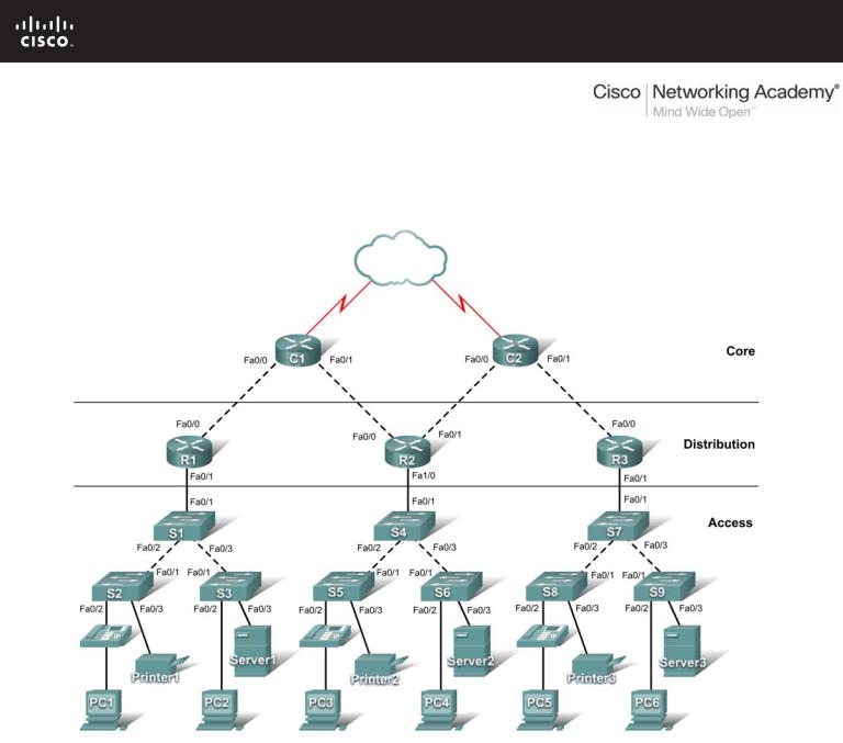
Topology Diagram
Learning Objectives
•Add devices to a topology.
•Connect the devices.
Introduction
Packet Tracer is integrated throughout this course. You must know how to navigate the Packet Tracer environment to complete this course. Use the tutorials if you need a review of Packet Tracer fundamentals. The tutorials are located in the Packet Tracer Help menu.
This activity focuses on building a hierarchical topology, from the core to the distribution and access layers.
All contents are Copyright © 1992–2007 Cisco Systems, Inc. All rights reserved. This document is Cisco Public Information. |
Page 1 of 3 |

CCNA Exploration |
|
LAN Switching and Wireless: LAN Design |
PT Activity 1.2.4: Build a Hierarchical Topology |
Task 1: Add Devices to the Topology
Step 1. Add the missing distribution layer routers.
The routers you need are located in Custom Made Devices. R1 and R3 are 1841 routers. Ctrl-click the 1841 router to add more than one. Press ESC to cancel. R2 is a 2621XM router.
Step 2. Add the remaining access layer switches.
Following the topology diagram, add nine 2960-24TT switches to complete the rest of the access layer. Remember you can use press Ctrl-click to add multiple devices of the same type.
Step 3. Change the display name for each new device.
•Click a device to open its configuration window.
•Select the Config tab to access the basic configuration options.
•In Global Settings under Display Name and Hostname, type the name for the device shown in the topology diagram.
•Repeat the process for all the new devices that you added.
Although Packet Tracer does not score adding the display names, this step must be completed to successfully complete this activity.
Step 4. Check results.
Your completion percentage should be 14%. If not, click Check Results to see which required components are not yet completed.
Task 2: Connect the Devices
Pay close attention to the topology diagram and the labeled interfaces when connecting the devices. You are graded on the connections. For instance, in the topology diagram switch S1 is connected to R1 through interface Fa0/1 on both sides. This connection is scored on both the cable type and interface designation. Do not use the Smart Connection utility to make these connections because you have no control over which interface is selected.
Step 1. Cable the core layer routers to the distribution layer routers.
•Using copper crossover cables, connect the core layer routers, C1 and C2, to the distribution layer routers, R1, R2, and R3.
•C1 connects to both R1 and R2, and C2 connects to both R2 and R3.
•As with devices, you can Ctrl-click the cable type to make multiple connections without having to re-select the cable.
•Remember to refer to the topology diagram to determine which interfaces to use for these connections.
Step 2. Cable the distribution layer routers to the access layer switches.
Connect the distribution layer routers to the access layer switches using copper straight-through cables. R1 connects to S1, R2 connects to S4, and R3 connects to S7.
Step 3. Cable the access layer switches.
Connect the access layer switches using copper crossover cables. Follow the topology diagram for the correct connections.
All contents are Copyright © 1992–2007 Cisco Systems, Inc. All rights reserved. This document is Cisco Public Information. |
Page 2 of 3 |

CCNA Exploration |
|
LAN Switching and Wireless: LAN Design |
PT Activity 1.2.4: Build a Hierarchical Topology |
Step 4. Cable the end devices.
Connect the remaining end devices (IP phones, printers, PCs, and servers) to the correct switch using copper straight-through cables. When connecting a switch to a PC, remember to connect to the Fast Ethernet port of the PC.
Step 5. Check results.
Your completion percentage should be 100%. If not, click Check Results to see which required components are not yet completed.
Note: A bug in Packet Tracer may cause your percentage to show only 99% even though all the required components are complete. If you wait long enough, Packet Tracer eventually catches up and gives you the full 100%.
Step 6. Reflection.
Notice that the link lights for ports between switches and between a switch and an end device eventually transition from amber to green. Why are the link lights for ports between routers and for ports between routers and switches red?
____________________________________________________________________________________
____________________________________________________________________________________
____________________________________________________________________________________
All contents are Copyright © 1992–2007 Cisco Systems, Inc. All rights reserved. This document is Cisco Public Information. |
Page 3 of 3 |

PT Activity 1.3.1: Review of Concepts from Exploration 1
Topology Diagram
NOTE TO USER: This activity is a variation of lab 1.3.1. This Packet Tracer Activity is not a companion for the above named lab. The instructions for completing this activity are found within this activity.
Learning Objectives
•Design a logical LAN topology.
•Configure the physical topology.
•Configure the logical topology.
•Verify network connectivity.
•Verify passwords.
Introduction
In this activity, you will design and configure a small routed network and verify connectivity across multiple network devices. This requires creating and assigning two subnetwork blocks, connecting hosts and network devices, and configuring host computers and one Cisco router for basic network connectivity. Switch1 has a default configuration and does not require additional configuration. You will use common commands to test and document the network. The zero subnet is used.
Task 1: Design a Logical LAN Topology
Step 1. Design an IP addressing scheme.
Given the IP address block of 192.168.7.0 /24, design an IP addressing scheme that satisfies the following requirements:
|
Subnet |
|
|
Number of |
|
|
|
||||
|
|
|
Hosts |
|
|
|
|
|
|
|
|
|
|
|
|
|
|
|
Subnet A |
110 |
|
||
|
|
|
|
|
|
All contents are Copyright © 2007-2008 Cisco Systems, Inc. All rights reserved. This document is Cisco Public Information. Page 1 of 4

CCNA Exploration |
|
LAN Switching and Wireless: LAN Design |
PT Activity 1.3.1: Review of Concepts from Exploration 1 |
|
Subnet |
|
|
Number of |
|
|
|
||||
|
|
|
Hosts |
|
|
|
|
|
|
|
|
|
|
|
|
|
|
|
Subnet B |
54 |
|
||
|
|
|
|
|
|
Subnet zero is used. No subnet calculators may be used. Create the smallest possible subnets that satisfy the requirements for hosts. Assign the first usable subnet to Subnet A.
Host computers will use the first IP address in the subnet. The network router will use the last IP address in the subnet.
Step 2. Write down the IP address information for each device.
Before proceeding, verify your IP addresses with the instructor.
Task 2: Configure the Physical Topology
Step 1. Cable the network.
•Connect Host1 to the Fa0/0 interface on Router1
•Connect a console cable between Host1 and Router1
•Connect the Fa0/1 interface on Switch1 to the Fa0/1 interface on Router1
•Connect Host2 to the Fa0/2 interface on Switch1
Step 2. Inspect the network connections.
Verify the connections visually.
Task 3: Configure the Logical Topology
Step 1. Configure the host computers.
Configure the static IP address, subnet mask, and gateway for each host computer.
Step 2. Configure Router1.
Connect to Router1 through the Terminal connection on Host1. Enter the following commands on the router:
Remember: Packet Tracer is case sensitive when it grades the description command.
Router>enable
Router#config term
Enter configuration commands, one per line. End with CNTL/Z. Router(config)#hostname Router1
Router1(config)#enable secret class
Router1(config)#line console 0 Router1(config-line)#password cisco Router1(config-line)#login Router1(config-line)#line vty 0 4 Router1(config-line)#password cisco Router1(config-line)#login Router1(config-line)#int fa0/0
Router1(config-if)#ip address addr sub_mask !Supply your answer from Task 1 Router1(config-if)#no shutdown
Router1(config-if)#description connection to host1
Router1(config-if)#interface fa0/1
All contents are Copyright © 2007-2008 Cisco Systems, Inc. All rights reserved. This document is Cisco Public Information. |
Page 2 of 4 |

CCNA Exploration |
|
LAN Switching and Wireless: LAN Design |
PT Activity 1.3.1: Review of Concepts from Exploration 1 |
Router1(config-if)#description connection to switch1
Router1(config-if)#ip address addr sub_mask !Supply your answer from Task 1 Router1(config-if)#no shutdown
Router1(config-if)#end Router1#
Task 4: Verify Network Connectivity
Step 1. Use the ping command to verify network connectivity.
You can verify network connectivity using the ping command.
Step 2. Check results.
Your completion percentage should be 100%. If not, click Check Results to see which required components are not yet completed.
Task 5: Verify Passwords
Step 1. Telnet to the router from Host2 and verify the Telnet password.
You should be able to telnet to either Fast Ethernet interface of the router.
In a command window on Host 2, type:
Packet Tracer PC Command Line 1.0
PC>telnet 192.168.7.190
Trying 192.168.7.190 ...
User Access Verification
Password:
When you are prompted for the Telnet password, type cisco and press Enter.
Step 2. Verify that the enable secret password has been set.
From the Telnet session, enter privileged EXEC mode and verify it is password protected:
Router1>enable
Were you prompted for the enable secret password?
____________________________________________________________________________________
____________________________________________________________________________________
Task 6: Reflection
How are Telnet access and console access different?
____________________________________________________________________________________
____________________________________________________________________________________
____________________________________________________________________________________
____________________________________________________________________________________
When might it make sense to set different passwords on these two access ports?
____________________________________________________________________________________
All contents are Copyright © 2007-2008 Cisco Systems, Inc. All rights reserved. This document is Cisco Public Information. |
Page 3 of 4 |

CCNA Exploration |
|
LAN Switching and Wireless: LAN Design |
PT Activity 1.3.1: Review of Concepts from Exploration 1 |
____________________________________________________________________________________
Why does the switch between Host2 and the router not require configuration with an IP address to forward packets?
____________________________________________________________________________________
____________________________________________________________________________________
____________________________________________________________________________________
____________________________________________________________________________________
All contents are Copyright © 2007-2008 Cisco Systems, Inc. All rights reserved. This document is Cisco Public Information. |
Page 4 of 4 |