

Shearing force and bending moment definition of beams and types of loading
A bar acted upon by forces or couples in an axial plane, which chiefly cause bending of the bar, is termed a beam. Beams are usually classified as follows according to the manner of support and loading.
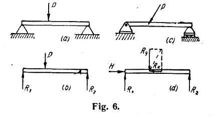
Simple Beams. — A beam freely supported at the ends is termed a simple beam. Fig. 6a shows a simple beam, resting on two supports, which carries a single concentrated load applied transversely (that is, perpendicular to the axis of the beam). The reactions exerted by the supports are assumed to be vertical as shown by the force arrows Rt and R2 in Fig. 6b. Fig. 6c shows a simple beam acted on by an oblique force P. This force has a vertical or transverse component Ry and a horizontal component Rx. In this case one of the supports must be a hinged immovable support so as to resist the thrust Rx. The reactive elements are three in number and are indicated by H, R
 and
R2
in
Fig. 6d. The reactions for either of these beams are found by
applying the conditions for static equilibrium; namely, M = 0 and 2Y
= 0 for Fig. 6b and M = 0, Y = 0 and 2X = 0 for Fig. 6d.
and
R2
in
Fig. 6d. The reactions for either of these beams are found by
applying the conditions for static equilibrium; namely, M = 0 and 2Y
= 0 for Fig. 6b and M = 0, Y = 0 and 2X = 0 for Fig. 6d.
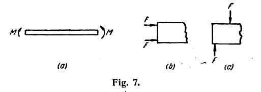
Beams in Pure Bending.— When a beam or a portion of a beam is acted on by couples only, it is said to be in pure bending. It will be seen later that there are no shearing forces acting on the cross sections of such beams. Fig. 7a shows beam acted on by end or terminal couples, which are represented in this book by curved arrows. Two simple ways in which these end couples may be applied are shown in Figures 7b and c.
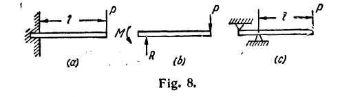
Cantilever Beams.— If the beam is supported only at one end by being built into a wall as in Fig. 8a or supported as shown in Fig. 8c, it is called a cantilever beam.
In Fig. 9a, there is shown a cantilever beam acted on by a force couple at the right end. The nature of the forge system at the built-in end is rather complicated but is equivalent to another couple produced as follows. At the wall, the pressures exerted by the masonry on the left end of the beam are distributed approximately as
shown in Fig. 9b. The resultant of these pressures on the top and bottom of the built-in end is a couple made up9 of the two equal forces F. For static equilibrium, the moment of this couple must be equal and opposite to that1 of the force couple at the right end.
The force system at the built-in end of the cantilever beam of Fig. 8a is equivalent to a couple M and a vertical reaction P as in directed in the free body of Fig. 8b. The magnitudes of the reactive elements M and P are found from the equilibrium conditions, M = 0 and
Types of Loading. — Loading by means of concentrated forces and end couples have been discussed above. Frequently the load is distributed over part of the length or the entire length of the beam. If the distributed load is of uniform intensity over the beam as in Fig. 11, it is called a uniformly distributed load. Or the distributed load may be of varying intensity as, for example, the uniformly varying load in Fig. 10.
To
get the reactions set up by a distributed load, one needs only
to consider the load replaced by an equivalent concentrated force
 acting
at its center of gravity. The conditions for static
equilibrium may
then be applied as in the case of concentrated forces.
acting
at its center of gravity. The conditions for static
equilibrium may
then be applied as in the case of concentrated forces.
 There
may also be various combinations of these loadings. The loads
usually act all in one plane known as the plane of loading.
There
may also be various combinations of these loadings. The loads
usually act all in one plane known as the plane of loading.
Shearing Force and Bending Moment. — When a beam is subjected to bending, internal stresses are set up. In order to determine the magnitudes of these stresses, it is necessary to know the bending moment and shearing force (to be defined below) acting at various cross sections of the beam. The primary concern of this chapter will be the determination of such bending moments and shearing forces.
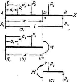
In order to define shearing force and bending moment, consider the beam of Fig. 12a to be cut at a section mn and the left portion isolated as in Fig. 12b. To hold the free-body portion in equilibrium, there must be a force V and a couple M acting
Fig. 12. at the cross section.
The existence of V and M may be visualized as follows. The two portions which have been separated at mn (Fig. 12) tend to rotate and to translate relative to each other. The clockwise rotation may be prevented by inserting» a link at the bottom and a roller at the top as in Fig. 13a. The link evidently is in tension
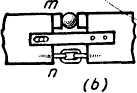
Fig. 13.
and so exerts a tensile force T on each of the adjacent portions while the roller is in compression and exerts a compressive force C. The tensile force T is equal to the compressive force С because no other horizontal forces act on the left portion (Fig. 12b) and because, for static equilibrium, X=0; consequently the forces С and T form a couple (Fig. 13) whose moment M is commonly called the resisting moment. In the uncut beam, the internal stress components, which are norm 11 to the cross section, set up a couple which is exactly equivalent to that1 described above as made up of С and T.
But this link and roller connection alone will not counteract^ the tendency of the left portion to move upward (assuming R1>P1+ P2) relative F to the right portion due to the unbalance of the external transverse forces. To prevent this relative sliding some additional device, such as the slotted bar in Fig. 13, will be needed and the bar will exert a downward force V on the left portion. This internal shearing force V in the uncut beam is really the resultant of shearing stresses acting over the cross section mn.
The resultant force system acting on the cross section is therefore, that shown in Fig. 13, namely a resisting couple M made up of the equal forces T and C, and the internal shearing force V. For static equilibrium of the left portion of the beam shown in Fig. 12b, Y=0, and so the force V is equal and opposite to the algebraic sum of the forces R1, P1, P2; that is,
V=R1 — P1 — P2. (10)
This algebraic sum of all the vertical forces to one side of the section mn is called the shearing force at the cross section mn. It is to be emphasized that the shearing force thus defined is opposite to the internal shearing force but of the same magnitude and will be designated by the common letter V. It is also necessary for static equilibrium that M = 0, and so the internal couple of magnitude M is equal and opposite to the algebraic sum of the moments of the forces R1, P1, and P2 with respect to then cross section mn; that is,
M = R1x— Pl(x — al) — P2(x — at) (11)
The algebraic sum of the moments of the external forces to one side of the cross section mn is called the bending moment at the cross section mn. Hence the bending moment as thus defined is opposite in sense to the internal resisting moment but is of the same magnitude and may be designated by the same letter M.
If, instead of the left portion of the beam, the right portion be considered, the shearing force V and the couple M will have the same magnitudes as above but opposite senses (Fig. 12c). This follows from the fact that the loads P1, P2, P3 acting on the beam are in equilibrium with the reactions R1 and R2 hence the moment of all these forces with respect to any point in the xy-plane, as well as their algebraic sum, must be equal to zero. Then the moment of forces acting on the left portion of the beam with respect to the section mn must be equal and opposite to the moment, with respect to the same section, of forces acting on the right portion of the beam. Also the algebraic sum of forces acting on the left portion of the beam must be equal and opposite to the algebraic sum of forces acting on the right portion.
In the following discussion the bending moment and the shearing force are taken as positive if they have the senses indicated in Fig. 12b, c, that is, the bending moment is positive if it produces bending of the beam concave upward and the shearing force is positive if the right portion of the beam tends to shear downward with respect to the left. See Fig. 14.
Positive Bending Negative Bending


Positive Shear Negative Shear


Fig. 14.
An equivalents, and perhaps even simpler, rule for determining the sign of the bending moment which act on a cross section is to say that upward external forces produce positive moments with respect to the cross section; downward forces, negative moments. For example, the moment caused by R1 in Fig. 12 is R1x and is positive because R1 acts upward. The moment caused by P1 is P1 (x — ax) and is negative because P1 acts downward. These signs agree with those of the corresponding terms in eq (11). The total bending moment acting on the cross section is positive or M negative according as the sum of the individual terms is positive or negative.