

Micro-Cap v7.1.6 / RM
.PDF•Stimulus generator examples..................................... |
575 |
• The File Stimulus device .......................................... |
581 |
• File Stimulus input file format................................... |
581 |
• I/O model ................................................................. |
587 |
•Digital/analog interface devices ................................. |
590 |
• Digital input device (N device).................................. |
590 |
• Digital output device (O device) ............................... |
594 |
Chapter 24 - Fourier Analysis and Digital Signal Processing
• What's in this chapter ............................................... |
597 |
•How digital signal processing functions work ........... |
598 |
•Digital Signal Processing functions ........................... |
600 |
• A DSP example ........................................................ |
606 |
• The DSP Parameters dialog box ............................... |
611 |
Chapter 25 - Libraries |
|
• What's in this chapter ............................................... |
615 |
• The Shape library ..................................................... |
616 |
• The Component library ............................................ |
616 |
• The Component library ............................................ |
616 |
• The Model library ..................................................... |
617 |
• Adding new parts to the Model library ..................... |
618 |
• How models are accessed ......................................... |
619 |
Chapter 26 - Performance Functions |
|
• What's in this chapter ............................................... |
621 |
• What are performance functions? ............................. |
622 |
• Performance functions defined ................................. |
623 |
• The Performance Function dialog box ...................... |
627 |
• Performance function plots....................................... |
630 |
Chapter 27 - 3D Graphs |
|
• What's in this chapter ............................................... |
639 |
• How 3D plotting works ............................................ |
640 |
• 3D example............................................................... |
641 |
• The Properties dialog box for 3D plots ..................... |
644 |
• Cursor mode in 3D ................................................... |
650 |
• 3D Performance functions ........................................ |
651 |
• Changing the plot orientation .................................... |
653 |
• Scaling in 3D ............................................................ |
654 |
ix
Chapter 28 - Optimizer |
|
• What's in this chapter ............................................... |
655 |
• How the optimizer works ......................................... |
656 |
• The Optimize dialog box ........................................... |
657 |
•Optimizing low frequency gain ................................. |
661 |
•Optimizing matching networks.................................. |
664 |
• Curve fitting with the optimizer ................................ |
667 |
Appendices |
|
• Appendix A File types............................................... |
671 |
• Appendix B Model library files ................................. |
673 |
• Appendix C Sample circuit files ................................ |
677 |
• Appendix D Accelerator keys ................................... |
681 |
Index........................................................................... |
683 |
x

Typographic conventions
Certain typographic conventions are employed to simplify reading and using the manuals. Here are the guidelines:
1.Named keys are denoted by the key name alone. For example: Press HOME, then press ENTER.
2.Text that is to be typed by the user is denoted by the text enclosed in double quotes. For example:
Type in the name "TTLINV".
3. Combinations of two keys are shown with the key symbols separated by a plus sign. For example:
ALT + R
4. Option selection is shown hierarchically. For example this phrase:
Options / Preferences / Common Options / General / Sound
means the Sound item from General section of the Common group on the Preferences dialog box, from the Options menu.
5.Square brackets are used to designate optional entries. For example: [Low]
6.The characters "<" and ">" bracket required entries. For example: <emitter_lead>
7.User entries are shown in italics. For example:
emitter_lead
8. The OR symbol ( | ) designates mutually exclusive alternatives. For example, PUL | EXP | SIN means PUL or EXP or SIN.
xi
xii

Chapter 1 Windows Basics
What's in this chapter
This chapter introduces and reviews the basics of working with Windows. It describes the common Windows structures including menus, dialog boxes, text boxes, list boxes, drop-down list boxes, option buttons, and check boxes. It also covers basic mouse and keyboard handling techniques and describes the difference between selecting and choosing.
1
Introduction
MC7 is a Windows program. To use the program, it is necessary to understand how Windows itself operates. Even though it is assumed that you are familiar with the Windows system, this chapter provides a brief introduction and review of the basic Windows features. If you feel a need for more information after reading this chapter, review the first chapter in the Windows User Guide that came with your Windows operating system. It has an excellent introduction to Windows. Much of what we present here is adapted from the Guide.
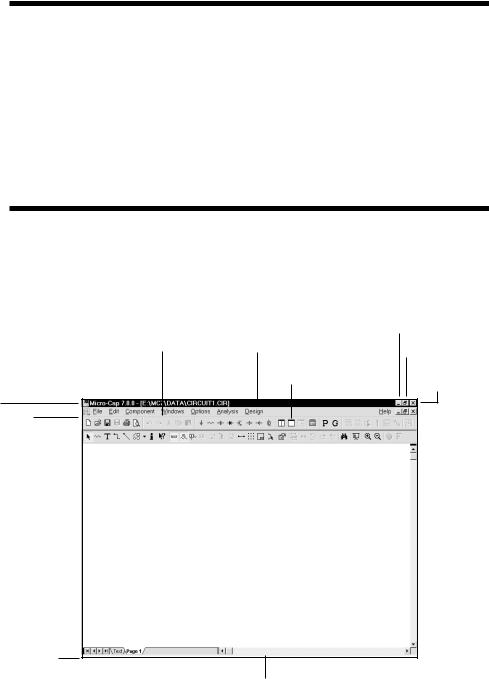
Parts of a window
Most MC7 operations are performed from within overlapping rectangular regions called windows. In this section we describe the parts common to most of these windows, and defer for later the more specialized MC7 functions.
|
|
Minimizebutton |
Menu bar |
Title bar |
Minimize / Restore |
button |
||
|
Tool bar |
Close button |
Control menu box
Circuit control menu box
|
|
|
Vertical |
|
Windows border |
|
|
|
scroll bar |
|
|
|||
Window corner
Horizontal scroll bar
Figure 1-1 The parts of a window
2 Chapter 1: Windows Basics
The various parts of a window and their purposes are as follows:
Control menu box
The Control menu box is located in the upper-left corner of the window. This box is a standard feature of all Windows applications and is mainly used to control the MC7 window size and location on the desktop. It lets you re-size, move, maximize, minimize, and close the MC7 window. The mouse can also be used to perform these tasks by dragging.
Circuit control menu box
The Circuit control menu box is similar to the standard control-menu box except that it controls a circuit window only. There can be many circuit windows open simultaneously. This standard Windows structure is provided for management of circuit windows, but there are easier ways to manipulate circuit windows. These will be described in later chapters.
Menu bar
This bar shows the available menus. A menu is a list of commands or options that lets you access various program features. Some items on a menu have an immediate effect. For example, when you choose Save from the File menu, the current circuit is saved to disk immediately. Other menu items control deferred actions or behavior. For example, when you choose Wire from the Mode item of the Options menu, nothing happens immediately. When you later drag the mouse in the circuit window, it draws a wire, instead of drawing a component or text.
Title bar
The title bar shows the name of the window. If the window is a circuit window, the title shows the circuit name and directory path. If the window is a dialog or text box the title shows the name of the dialog or text box. If the window is an analysis output window, such as numeric output, the title shows the file name and path of the file where the numeric output has been saved to disk.
Tool bar
The tool bar shows the tool buttons. These are graphical equivalents of the menu items. Clicking on a tool bar button is the same as clicking on its equivalent menu item. Tool bar buttons provide convenient, quick access to frequently used menu items. Immediate action buttons temporarily depress when clicked, then spring back. Modal buttons stay depressed until another mode is chosen. A depressed modal button means that the mode is enabled. This is the same as its corresponding menu item having a check mark.
3
Close button
The Close button closes the window.
Maximize / Restore button
The Restore button restores the windows former size.
Minimize button
The Minimize button reduces the window to an icon.
Scroll bars
The scroll bars are used to pan the window document. If the window is a circuit, the scroll bars are one of several ways to view different parts of the circuit. If the scroll bars are part of a list box, they let you browse the list.
Window border
The window border is a control object on the outside edge of the window. When the mouse passes over the edge, the cursor changes to a vertical or horizontal double arrow. A mouse drag then moves the underlying border, changing the window size and proportions.
Window corner
The window corner is a control object on the corner of the window. When the mouse passes over the corner, the cursor changes to a diagonal double arrow. A drag here simultaneously moves the two corner sides, changing the window size.
4 Chapter 1: Windows Basics

Basic mouse and keyboard techniques
This section explains the basic terms and techniques used to select and choose items from windows, menus, list boxes, and dialog boxes. The definitions of the more common terms are as follows:
This Term |
Means |
Click |
To quickly press and release a mouse button. |
Double-click |
To click a mouse button twice in rapid succession. |
Drag |
To hold the mouse button while you move the mouse. |
Point |
To move the mouse until the mouse pointer is at the |
|
desired location on the screen. |
Mouse button means the left mouse button, unless otherwise specified. The right mouse button is reserved for specialized functions.
The terms choose and select have two distinct meanings. To select something means to mark it, usually as a prelude to choosing it. To choose means to use the mouse or keyboard to pick or activate the selected item, option, or action.
Selecting is done by clicking the item with the cursor or dragging the cursor over a region containing the object. Selected text in a text field or in the text area appears in reversed video. Selected schematic objects, including text objects, are shown in the user-specified select color. Selected items from a window or dialog box may be shown as a highlight, or a dotted rectangle.
To choose a selected item in a dialog box, you click it with the mouse or press the SPACEBAR key. Highlighted buttons are chosen by pressing ENTER.
Accelerator keys are provided for some of the more frequently used menu items. Like tool bar buttons, they provide a quick and ready way to choose or activate common menu items. The keys are shown on the menus, adjacent to the items they activate.
Accelerator keys are well worth learning. For frequently used features, they can save a lot of time. Appendix D has a list of the accelerator keys.
5

Menus
Menus provide the basic commands and options that let you use MC7 features.
To select a menu:
Mouse
Using the mouse pointer, point to the name of the menu on the menu bar, and click the left mouse button. This opens the menu and displays its contents. You can also drag the mouse from the menu name directly to the item name and release the button to choose it.
Keyboard
If the menu name contains an underlined letter, press ALT + underlined letter. Alternatively, use this method:
•Press ALT to select the menu bar.
•Press LEFT ARROW or RIGHT ARROW to select the desired menu.
•Press ENTER to open the selected menu.
To close a menu:
Click anywhere outside the menu or press the ESC key.
To choose an item from a menu:
Click the mouse on the item name or use UP ARROW or DOWN ARROW keys to select the item, and then press ENTER to choose the item.
|
Menu conventions: |
|
|
Convention |
Meaning |
|
Dimmed or missing item |
The item is not available or simply inappropriate. |
|
|
For example, the Copy command is dimmed |
|
|
when nothing is selected. |
|
Ellipsis (... ) |
A dialog box appears revealing more choices to |
|
|
be made before the command can be completed. |
|
Check mark |
A check mark means the option is in effect. |
|
A key combination |
The key combination is a shortcut for this item. |
|
A triangle |
This indicates that a cascading menu appears |
|
|
listingadditionalchoices. |
6 |
Chapter 1: Windows Basics |
|