

RADIO AIDS
.pdf20 |
RADIO AIDS |
4 SEP 09 |
SECTION 1. NAVIGATION AIDS
1-1-9 INSTRUMENT LANDING
SYSTEM (ILS)
a.General
1.The ILS is designed to provide an approach path for exact alignment and descent of an aircraft on final approach to a runway.
2.The ground equipment consists of two highly directional transmitting systems and, along the approach, three (or fewer) marker beacons. The directional transmitters are known as the localizer and glide slope transmitters.
3.The system may be divided functionally into three parts:
(a)Guidance information: localizer, glide slope;
(b)Range information: marker beacon, DME; and
(c)Visual information: approach lights, touchdown and centerline lights, runway lights.
4.Precision radar, or compass locators located at the Outer Marker (OM) or Middle Marker (MM), may be substituted for marker beacons. DME, when specified in the procedure, may be substituted for the OM.
5.Where a complete ILS system is installed on each end of a runway; (i.e., the approach end of Runway 4 and the approach end of Runway 22) the ILS systems are not in service simultaneously.
b.Localizer
procedure is published for that particular runway and the approach is authorized by ATC.
4.Identification is in International Morse Code and consists of a three-letter identifier preceded by the letter I (••) transmitted on the localizer frequency.
EXAMPLE: I-DIA
5.The localizer provides course guidance throughout the descent path to the runway threshold from a distance of 18 NM from the antenna between an altitude of 1,000 feet above the highest terrain along the course line and 4,500 feet above the elevation of the antenna site. Proper off-course indications are provided throughout the following angular areas of the operational service volume:
(a)To 10 degrees either side of the course along a radius of 18 NM from the antenna; and
(b)From 10 to 35 degrees either side of the course along a radius of 10 NM. (See FIG 1-1-6.)
1.The localizer transmitter operates on one of 40 ILS channels within the frequency range of 108.10 to 111.95 MHz. Signals provide the pilot with course guidance to the runway centerline.
2.The approach course of the localizer is called the front course and is used with other functional parts, e.g., glide slope, marker beacons, etc. The localizer signal is transmitted at the far end of the runway. It is adjusted for a course width of (full scale fly-left to a full scale fly-right) of 700 feet at the runway threshold.
3.The course line along the extended centerline of a runway, in the opposite direction to the front course is called the back course.
CAUTION: Unless the aircraft’s ILS equipment includes reverse sensing capability, when flying inbound on the back course it is necessary to steer the aircraft in the direction opposite the needle deflection when making corrections from off-course to on-course. This “flying away from the needle” is also required when flying outbound on the front course of the localizer. Do not use back course signals for approach unless a back course approach
© JEPPESEN, 1994, 2009. ALL RIGHTS RESERVED.

4 SEP 09 |
RADIO AIDS |
21 |
SECTION 1. NAVIGATION AIDS
FIGURE 1-1-6
Limits of Localizer Coverage
6.Unreliable signals may be received outside these areas.
c.Localizer Type Directional Aid (LDA)
1.The LDA is of comparable use and accuracy to a localizer but is not part of a complete ILS. The LDA course usually provides a more precise approach course than the similar Simplified Directional Facility (SDF) installation, which may have a course width of 6 or 12 degrees.
2.The LDA is not aligned with the runway. Straight-in minimums may be published where alignment does not exceed 30 degrees between the course and runway. Circling minimums only are published where this alignment exceeds 30 degrees.
3.A very limited number of LDA approaches also incorporate a glideslope. These are annotated in the plan view of the instrument approach chart with a note, “LDA/Glideslope.” These procedures fall under a newly defined category of approaches called Approach with Vertical Guidance (APV) described in paragraph 5-4-5, Instrument Approach Procedure Charts, subparagraph a7(b), Approach with Vertical Guidance (APV). LDA minima for with and without glideslope is provided and annotated on the minima lines of the approach chart as S-LDA/GS and S-LDA. Because the final approach course is not aligned with the runway centerline, additional maneuvering will be required compared to an ILS approach.
d.Glide Slope/Glide Path
1.The UHF glide slope transmitter, operating on one of the 40 ILS channels within the frequency range 329.15 MHz, to 335.00 MHz radiates its signals in the direction of the localizer front course. The term “glide path” means that portion of the glide slope that intersects the localizer.
CAUTION: False glide slope signals may exist in the area of the localizer back course approach which can cause the glide slope flag alarm to disappear and present unreliable glide slope information. Disregard all glide slope signal indications when making a localizer back course approach unless a glide slope is specified on the approach and landing chart.
2.The glide slope transmitter is located between 750 feet and 1,250 feet from the approach end of the runway (down the runway) and offset 250 to 650 feet from the runway centerline. It transmits a glide path beam 1.4 degrees wide (vertically). The signal provides descent information for navigation down to the lowest authorized decision height (DH) specified in the approved ILS approach procedure. The glidepath may not be suitable for navigation below the lowest authorized DH and any reference to glidepath indications below that height must be supplemented by visual reference to the runway environment. Glidepaths with no published DH are usable to runway threshold.
3.The glide path projection angle is normally adjusted to 3 degrees above horizontal so that it intersects the MM at about 200 feet and the OM at about 1,400 feet above the runway elevation. The glide slope is normally usable to the distance of 10 NM. However, at some locations, the glide slope has been certified for an extended service volume which exceeds 10 NM.
4.Pilots must be alert when approaching the glidepath interception. False courses and reverse sensing will occur at angles considerably greater than the published path.
5.Make every effort to remain on the indicated glide path.
© JEPPESEN, 1994, 2009. ALL RIGHTS RESERVED.

22 |
RADIO AIDS |
4 SEP 09 |
SECTION 1. NAVIGATION AIDS
CAUTION: Avoid flying below the glide path to assure obstacle/terrain clearance is maintained.
6.The published glide slope threshold crossing height (TCH) DOES NOT represent the height of the actual glide path on-course indication above the runway threshold. It is used as a reference for planning purposes which represents the height above the runway threshold that an aircraft’s glide slope antenna should be, if that aircraft remains on a trajectory formed by the four-mile-to- middle marker glidepath segment.
7.Pilots must be aware of the vertical height between the aircraft’s glide slope antenna and the main gear in the landing configuration and, at the DH, plan to adjust the descent angle accordingly if the published TCH indicates the wheel crossing height over the runway threshold may not be satisfactory. Tests indicate a comfortable wheel crossing height is approximately 20 to 30 feet, depending on the type of aircraft.
NOTE: The TCH for a runway is established based on several factors including the largest aircraft category that normally uses the runway, how airport layout effects the glide slope antenna placement, and terrain. A higher than optimum TCH, with the same glide path angle, may cause the aircraft to touch down further from the threshold if the trajectory of the approach is maintained until the flare. Pilots should consider the effect of a high TCH on the runway available for stopping the aircraft.
e.Distance Measuring Equipment (DME)
1.When installed with the ILS and specified in the approach procedure, DME may be used:
(a)In lieu of the OM;
(b)As a back course (BC) final approach fix (FAF); and
(c)To establish other fixes on the localizer course.
2.In some cases, DME from a separate facility may be used within Terminal Instrument Procedures (TERPS) limitations:
(a)To provide ARC initial approach segments;
(b)As a FAF for BC approaches; and
(c)As a substitute for the OM.
f.Marker Beacon
1.ILS marker beacons have a rated power output of 3 watts or less and an antenna array designed to produce an elliptical pattern with dimensions, at 1,000 feet above the antenna, of approximately 2,400 feet in width and 4,200 feet in length. Airborne marker beacon receivers with a selective sensitivity feature should always be operated in the “low” sensitivity position for proper reception of ILS marker beacons.
2.Ordinarily, there are two marker beacons associated with an ILS, the OM and MM. Locations with a Category II ILS also have an Inner Marker (IM). When an aircraft passes over a marker, the pilot will receive the indications shown in TBL 1-1-3.
(a)The OM normally indicates a position at which an aircraft at the appropriate altitude on the localizer course will intercept the ILS glide path.
(b)The MM indicates a position approximately 3,500 feet from the landing threshold. This is also the position where an aircraft on the glide path will be at an altitude of approximately 200 feet above the elevation of the touchdown zone.
(c)The IM will indicate a point at which an aircraft is at a designated decision height (DH) on the glide path between the MM and landing threshold.
TABLE 1-1-3 Marker Passage Indications
3.A back course marker normally indicates the ILS back course final approach fix where approach descent is commenced.
g.Compass Locator
1.Compass locator transmitters are often situated at the MM and OM sites. The transmitters have a power of less than 25 watts, a range of at least 15 miles and operate between 190 and 535 kHz. At some locations, higher powered radio beacons, up to 400 watts, are used as OM compass locators. These generally carry Transcribed Weather Broadcast (TWEB) information.
2.Compass locators transmit two letter identification groups. The outer locator transmits the first two letters of the localizer identification group, and the middle locator transmits the last two letters of the localizer identification group.
h.ILS Frequency (See TBL 1-1-4.)
TABLE 1-1-4 Frequency Pairs Allocated for ILS
© JEPPESEN, 1994, 2009. ALL RIGHTS RESERVED.

19 MAR 10 |
RADIO AIDS |
23 |
SECTION 1. NAVIGATION AIDS
TABLE 1-1-4 Frequency Pairs Allocated
for ILS (continued)
i.ILS Minimums
1.The lowest authorized ILS minimums, with all required ground and airborne systems components operative, are:
(a)Category I. Decision Height (DH) 200 feet and Runway Visual Range (RVR) 2,400 feet (with touchdown zone and centerline lighting, RVR 1,800 feet), or (with Autopilot or FD or HUD, RVR 1,800 feet);
(b)Special Authorization Category I.
DH 150 feet and Runway Visual Range (RVR) 1,400 feet, HUD to DH;
(c)Category II. DH 100 feet and RVR 1,200 feet (with autoland or HUD to touchdown and noted on authorization, RVR 1,000 feet);
(d)Special Authorization Category II with Reduced Lighting. DH 100 feet and RVR 1,200 feet with autoland or HUD to touchdown and noted on authorization (touchdown zone, centerline lighting, and ALSF-2 are not required);
(e)Category IIIa. No DH or DH below 100 feet and RVR not less than 700 feet;
(f)Category IIIb. No DH or DH below 50 feet and RVR less than 700 feet but not less than 150 feet; and
(g)Category IIIc. No DH and no RVR limitation.
NOTE: Special authorization and equipment required for Categories II and III.
j.Inoperative ILS Components
1.Inoperative localizer. When the localizer fails, an ILS approach is not authorized.
2.Inoperative glide slope. When the glide slope fails, the ILS reverts to a nonprecision localizer approach.
REFERENCE-
Jeppesen approach charts include adjustments to minimums due to inoperative airborne or ground system equipment.
k.ILS Course Distortion
1.All pilots should be aware that disturbances to ILS localizer and glide slope courses may occur when surface vehicles or aircraft are operated near the localizer or glide slope antennas. Most ILS installations are subject to signal interference by either surface vehicles, aircraft or both. ILS CRITICAL AREAS are established near each localizer and glide slope antenna.
2.ATC issues control instructions to avoid interfering operations within ILS critical areas at controlled airports during the hours the Airport Traffic Control Tower (ATCT) is in operation as follows:
(a)Weather Conditions. Less than ceiling 800 feet and/or visibility 2 miles.
(1)Localizer Critical Area.
Except for aircraft that land, exit a runway, depart or miss approach, vehicles and aircraft are not authorized in or over the critical area when an arriving aircraft is between the ILS final approach fix and the airport. Additionally, when the ceiling is less than 200 feet and/or the visibility is RVR 2,000 or less, vehicle and aircraft operations in or over the area are not authorized when an arriving aircraft is inside the ILS MM.
© JEPPESEN, 1994, 2010. ALL RIGHTS RESERVED.

24 |
RADIO AIDS |
19 MAR 10 |
SECTION 1. NAVIGATION AIDS
(2)Glide Slope Critical Area.
Vehicles and aircraft are not authorized in the area when an arriving aircraft is between the ILS final approach fix and the airport unless the aircraft has reported the airport in sight and is circling or side stepping to land on a runway other than the ILS runway.
(b)Weather Conditions. At or above ceiling 800 feet and/or visibility 2 miles.
(1)No critical area protective action is provided under these conditions.
(2)A flight crew, under these conditions, should advise the tower that it will conduct an AUTOLAND or COUPLED approach to ensure that the ILS critical areas are protected when the aircraft is inside the ILS MM.
EXAMPLE: Glide slope signal not protected.
FIGURE 1-1-7
3.Aircraft holding below 5,000 feet between the outer marker and the airport may cause localizer signal variations for aircraft conducting the ILS approach. Accordingly, such holding is not authorized when weather or visibility conditions are less than ceiling 800 feet and/or visibility 2 miles.
4.Pilots are cautioned that vehicular traffic not subject to ATC may cause momentary deviation to ILS course or glide slope signals. Also, critical areas are not protected at uncontrolled airports or at airports with an operating control tower when weather or visibility conditions are above those requiring protective measures. Aircraft conducting coupled or autoland operations should be especially alert in monitoring automatic flight control systems. (See FIG 1-1-7.)
NOTE: Unless otherwise coordinated through Flight Standards, ILS signals to Category I runways are not flight inspected below 100 feet AGL. Guidance signal anomalies may be encountered below this altitude.
FAA Instrument Landing Systems
© JEPPESEN, 1994, 2010. ALL RIGHTS RESERVED.

4 SEP 09 |
RADIO AIDS |
25 |
SECTION 1. NAVIGATION AIDS
1-1-10 SIMPLIFIED DIRECTIONAL
FACILITY (SDF)
a.The SDF provides a final approach course similar to that of the ILS localizer. It does not provide glide slope information. A clear understanding of the ILS localizer and the additional factors listed below completely describe the operational characteristics and use of the SDF.
b.The SDF transmits signals within the range of 108.10 to 111.95 MHz.
c.The approach techniques and procedures used in an SDF instrument approach are essentially the same as those employed in executing a standard localizer approach except the SDF course may not be aligned with the runway and the course may be wider, resulting in less precision.
d. Usable off-course |
indications |
are limited to |
35 degrees either |
side of the |
course center- |
line. Instrument indications received beyond 35 degrees should be disregarded.
e.The SDF antenna may be offset from the runway centerline. Because of this, the angle of convergence between the final approach course and the runway bearing should be determined by reference to the instrument approach procedure chart. This angle is generally not more than 3 degrees. However, it should be noted that inasmuch as the approach course originates at the antenna site, an approach which is continued beyond the runway threshold will lead the aircraft to the SDF offset position rather than along the runway centerline.
f.The SDF signal is fixed at either 6 degrees or 12 degrees as necessary to provide maximum flyability and optimum course quality.
g.Identification consists of a three-letter identifier transmitted in Morse Code on the SDF frequency. The appropriate instrument approach chart will indicate the identifier used at a particular airport.
1-1-11 MICROWAVE LANDING
SYSTEM (MLS)
a.General
1.The MLS provides precision navigation guidance for exact alignment and descent of aircraft on approach to a runway. It provides azimuth, elevation, and distance.
2.Both lateral and vertical guidance may be displayed on conventional course deviation indicators or incorporated into multipurpose cockpit displays. Range information can be displayed by conventional DME indicators and also incorporated into multipurpose displays.
3.The MLS supplements the ILS as the standard landing system in the U.S. for civil, military, and international civil aviation. At international airports, ILS service is protected to 2010.
4.The system may be divided into five functions:
(a)Approach azimuth;
(b)Back azimuth;
(c)Approach elevation;
(d)Range; and
(e)Data communications.
5.The standard configuration of MLS ground equipment includes:
(a)An azimuth station to perform functions (a) and (e) above. In addition to providing azimuth navigation guidance, the station transmits basic data which consists of information associated directly with the operation of the landing system, as well as advisory data on the performance of the ground equipment.
(b)An elevation station to perform function (c).
(c)Distance Measuring Equipment (DME) to perform range guidance, both standard DME (DME/N) and precision DME (DME/P).
6.MLS Expansion Capabilities. The standard configuration can be expanded by adding one or more of the following functions or characteristics.
(a)Back azimuth. Provides lateral guidance for missed approach and departure navigation.
(b)Auxiliary data transmissions.
Provides additional data, including refined airborne positioning, meteorological information, runway status, and other supplementary information.
(c)Expanded Service Volume (ESV) proportional guidance to 60 degrees.
7.MLS identification is a four-letter designation starting with the letter M. It is transmitted in International Morse Code at least six times per minute by the approach azimuth (and back azimuth) ground equipment.
b.Approach Azimuth Guidance
1.The azimuth station transmits MLS angle and data on one of 200 channels within the frequency range of 5031 to 5091 MHz.
2.The equipment is normally located about 1,000 feet beyond the stop end of the runway, but there is considerable flexibility in selecting sites. For example, for heliport operations the azimuth transmitter can be collocated with the elevation transmitter.
3.The azimuth coverage extends: (See FIG 1-1-8.)
(a)Laterally, at least 40 degrees on either side of the runway centerline in a standard configuration,
(b)In elevation, up to an angle of 15 degrees and to at least 20,000 feet, and
(c)In range, to at least 20 NM.
© JEPPESEN, 1994, 2009. ALL RIGHTS RESERVED.

26 |
RADIO AIDS |
4 SEP 09 |
SECTION 1. NAVIGATION AIDS
FIGURE 1-1-8
Coverage Volume Azimuth
c.Elevation Guidance
1.The elevation station transmits signals on the same frequency as the azimuth station. A single frequency is time-shared between angle and data functions.
2.The elevation transmitter is normally located about 400 feet from the side of the runway between runway threshold and the touchdown zone.
3.Elevation coverage is provided in the same airspace as the azimuth guidance signals:
(a)In elevation, to at least +15 degrees;
(b)Laterally, to fill the Azimuth lateral coverage; and
(c)In range, to at least 20 NM. (See FIG 1-1-9.)
FIGURE 1-1-9
Coverage Volumes Elevation
d.Range Guidance
1.The MLS Precision Distance Measuring Equipment (DME/P) functions the same as the navigation DME described in paragraph 1-1-7, Distance Measuring Equipment (DME), but there are some technical differences. The beacon transponder operates in the frequency band 962 to 1105 MHz and responds to an aircraft interroga-
tor. The MLS DME/P accuracy is improved to be consistent with the accuracy provided by the MLS azimuth and elevation stations.
2.A DME/P channel is paired with the azimuth and elevation channel. A complete listing of the 200 paired channels
of the DME/P with the angle functions is contained in FAA Standard 022 (MLS Interoperability and Performance Requirements).
3.The DME/N or DME/P is an integral part of the MLS and is installed at all MLS facilities unless a waiver is obtained. This occurs infrequently and only at outlying, low density airports where marker beacons or compass locators are already in place.
e.Data Communications
1.The data transmission can include both the basic and auxiliary data words. All MLS facilities transmit basic data. Where needed, auxiliary data can be transmitted.
2.Coverage limits. MLS data are transmitted throughout the azimuth (and back azimuth when provided) coverage sectors.
3.Basic data content. Representative data include:
(a)Station identification;
(b)Exact locations of azimuth, elevation and DME/P stations (for MLS receiver processing functions);
(c)Ground equipment performance level; and
(d)DME/P channel and status.
4.Auxiliary data content: Representative data include:
(a)3-D locations of MLS equipment;
(b)Waypoint coordinates;
(c)Runway conditions; and
(d)Weather (e.g., RVR, ceiling, altimeter setting, wind, wake vortex, wind shear).
f.Operational Flexibility
1.The MLS has the capability to fulfill a variety of needs in the approach, landing, missed approach and departure phases of flight. For example:
(a)Curved and segmented approaches;
(b)Selectable glide path angles;
(c)Accurate 3-D positioning of the aircraft in space; and
(d)The establishment of boundaries to ensure clearance from obstructions in the terminal area.
2.While many of these capabilities are available to any MLS-equipped aircraft, the more sophisticated capabilities (such as curved and segmented approaches) are dependent upon the particular capabilities of the airborne equipment.
g. Summary
© JEPPESEN, 1994, 2009. ALL RIGHTS RESERVED.

4 SEP 09 |
RADIO AIDS |
27 |
SECTION 1. NAVIGATION AIDS
1.Accuracy. The MLS provides precision three-dimensional navigation guidance accurate enough for all approach and landing maneuvers.
2.Coverage. Accuracy is consistent throughout the coverage volumes.
(See FIG 1-1-10.)
FIGURE 1-1-10
Coverage Volumes
3-D Representation
3.Environment. The system has low susceptibility to interference from weather conditions and airport ground traffic.
4.Channels. MLS has 200 channelsenough for any foreseeable need.
5.Data. The MLS transmits ground-air data messages associated with the systems operation.
6.Range information. Continuous range information is provided with an accuracy of about 100 feet.
1-1-12 NAVAID IDENTIFIER REMOVAL DURING MAINTENANCE
During periods of routine or emergency maintenance, coded identification (or code and voice, where applicable) is removed from certain FAA
NOTE: DO NOT attempt to fly a procedure that is NOTAMed out of service even if the identification is present. In certain cases, the identification may be transmitted for short periods as part of the testing.
1-1-13 NAVAIDS WITH VOICE
a.Voice equipped enroute radio navigational aids are under the operational control of either an FAA Automated Flight Service Station (AFSS) or an approach control facility. The voice communication is available on some facilities. Hazardous Inflight Weather Advisory Service (HIWAS) broadcast capability is available on selected VOR sites throughout the conterminous U.S. and does not provide two-way communication. The availability of two-way voice communication and HIWAS is indicated in the A/FD and aeronautical charts.
b.Unless otherwise noted on the chart, all radio navigation aids operate continuously except during shutdowns for maintenance. Hours of operation of facilities not operating continuously are annotated on charts and in the A/FD.
1-1-14 USER REPORTS ON NAVAID PERFORMANCE
a.Users of the National Airspace System (NAS) can render valuable assistance in the early correction of NAVAID malfunctions by reporting their observations of undesirable NAVAID performance. Although NAVAIDs are monitored by electronic detectors, adverse effects of electronic interference, new obstructions or changes in terrain near the NAVAID can exist without detection by the ground monitors. Some of the characteristics of malfunction or deteriorating performance which should be reported are: erratic course or bearing indications; intermittent, or full, flag alarm; garbled, missing or obviously improper coded identification; poor quality communications reception; or, in the case of frequency interference, an audible hum or tone accompanying radio communications or NAVAID identification.
b.Reporters should identify the NAVAID, location of the aircraft, time of the observation, type of aircraft and describe the condition observed; the type of receivers in use is also useful information. Reports can be made in any of the following ways:
1.Immediate report by direct radio communication to the controlling Air Route Traffic Control Center (ARTCC), Control Tower, or FSS. This method provides the quickest result.
2.By telephone to the nearest FAA facility.
© JEPPESEN, 1994, 2009. ALL RIGHTS RESERVED.
28 |
RADIO AIDS |
4 SEP 09 |
SECTION 1. NAVIGATION AIDS
c.In aircraft that have more than one receiver, there are many combinations of possible interference between units. This can cause either erroneous navigation indications or, complete or partial blanking out of the communications. Pilots should be familiar enough with the radio installation of the particular airplanes they fly to recognize this type of interference.
1-1-15 LORAN
a.Introduction
1.The Long Range Navigation-C (LORAN) system is a hyperbolic, terrestrial-based navigation system operating in the 90-110 kHz frequency band. LORAN, operated by the U.S. Coast Guard (USCG), has been in service for over 50 years and is used for navigation by the various transportation modes, as well as, for precise time and frequency applications. The system is configured to provide reliable, all weather navigation for marine users along the U.S. coasts and in the Great Lakes.
2.In the 1980’s, responding to aviation user and industry requests, the USCG and FAA expanded LORAN coverage to include the entire continental U.S. This work was completed in late 1990, but the LORAN system failed to gain significant user acceptance and primarily due to transmitter and
user equipment performance limitations, attempts to obtain FAA certification of nonprecision approach capable receivers were unsuccessful. More recently, concern regarding the vulnerability of Global Positioning System (GPS) and the consequences of losing GPS on the critical U.S. infrastructure (e.g., NAS) has renewed and refocused attention on LORAN.
3.LORAN is also supported in the Canadian airspace system. Currently, LORAN receivers are only certified for enroute navigation.
4. Additional information can be found in the “LORAN-C User Handbook,” COMDT PUBP16562.6, or the website http://www.navcen.uscg.gov.
b.LORAN Chain
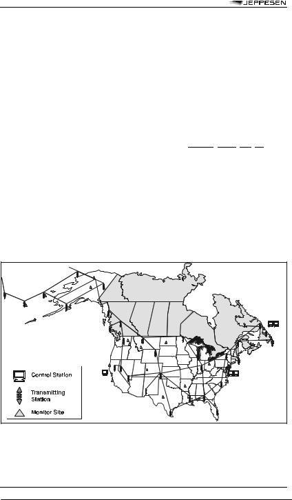
1.The locations of the U.S. and Canadian LORAN transmitters and monitor sites are illustrated in FIG 1-1-11. Station operations are organized into subgroups of four to six stations called “chains.” One station in the chain is designated the “Master” and the others are “secondary” stations. The resulting chain based coverage is seen in FIG 1-1-12.
FIGURE 1-1-11
U.S. and Canadian LORAN System Architecture
© JEPPESEN, 1994, 2009. ALL RIGHTS RESERVED.

4 SEP 09 |
RADIO AIDS |
29 |
SECTION 1. NAVIGATION AIDS
FIGURE 1-1-12
LORAN Chain Based Coverage
2.The LORAN navigation signal is a carefully structured sequence of brief radio frequency pulses centered at 100 kHz. The sequence of signal transmissions consists of a pulse group from the Master (M) station followed at precise time intervals by groups from the secondary stations, which are designated by the U.S. Coast Guard with the letters V, W, X, Y and Z. All secondary stations radiate pulses in groups of eight, but for identification the Master signal has an additional ninth pulse. (See FIG 1-1-13.) The timing of the LORAN system is tightly controlled and synchronized to Coordinated Universal Time (UTC). Like the GPS, this is a Stratum 1 timing standard.
3.The time interval between the reoccurrence of the Master pulse group is called the Group Repetition Interval (GRI). The GRI is the same for all stations in a chain and each LORAN chain has a unique GRI. Since all stations in a particular chain operate on the same radio frequency, the GRI is the key by which a LORAN receiver can identify and isolate signal groups from a specific chain.
EXAMPLE: Transmitters in the Northeast U.S. chain (FIG 1-1-14) operate with a GRI of 99,600 microseconds which is shortened to 9960 for convenience. The master station (M) at Seneca, New York, controls secondary stations (W) at Caribou, Maine; (X) at Nantucket, Massachusetts;
(Y)at Carolina Beach, North Carolina, and (Z) at Dana, Indiana. In order to keep chain operations precise, monitor
receivers are located at Cape Elizabeth, ME; Sandy Hook, NJ; Dunbar Forest, MI, and Plumbrook, OH. Monitor receivers continuously measure various aspects of the quality (e.g., pulse shape) and accuracy (e.g., timing) of LORAN signals and report system status to a control station.
4.The line between the Master and each secondary station is the “baseline” for a pair of stations. Typical baselines are from 600 to 1,000 nautical miles in length. The continuation of the baseline in either direction is a “baseline extension.”
5.At the LORAN transmitter stations there are cesium oscillators, transmitter time and control equipment, a transmitter, primary power (e.g., commercial or generator) and auxiliary power equipment (e.g., uninterruptible power supplies and generators), and a transmitting antenna (configurations may either have 1 or 4 towers) with the tower heights ranging from 700 to 1350 feet tall. Depending on the coverage area requirements a LORAN station transmits from 400 to 1,600 kilowatts of peak signal power.
6.The USCG operates the LORAN transmitter stations under a reduced staffing structure that is made possible by the remote control and monitoring of the critical station and signal parameters. The actual control of the transmitting station is accomplished remotely at Coast Guard Navigation Center (NAVCEN) located in Alexandria, Virginia. East Coast and Midwest stations are controlled by the NAVCEN. Stations on the West Coast and in Alaska are controlled
© JEPPESEN, 1994, 2009. ALL RIGHTS RESERVED.