

VI. Pitot – Static Tube
The most important and widely used tool for measurement of air speed is the pitot – static head. If we know the value of total pressure p0 and static pressure p, we know dynamic pressure, and the value of air speed
![]() ,
(2)
,
(2)
The pitot – static head consists of two metal tubes fixed to some exposed part of the aeroplane and facing directly into the airflow. One of these, the pitot (or pressure) tube has an open end facing the wind, while the other tube, called the static, is closed at the end but pierced with small holes or slits farther back. Sometimes the pitot tube is a short distance below the static (as in Figure 7), but on modern aircraft the tubes are more usually concentric, the pitot tube forming the centre and being surrounded by the static (Figure 8). The other end of each tube is connected by tubing to the air speed indicator in the cockpit.
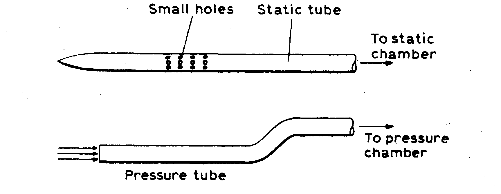
Pitot – static head
Figure 7
Old types of air speed indicator consisted of two chambers separated by a rubber, metal, or oiled-silk diaphragm, one tube being connected to each chamber, which was otherwise airtight. In a later development the pitot tube is connected to the inside of a capsule (a flat circular box of corrugated metal such as is used in an altimeter or aneroid barometer), while the static tube is connected to the casing of the instrument. In each type the principle is the same: when there is no air speed the normal atmospheric pressure will be communicated to both sides of the diaphragm or capsule, but when the air blows up against the open pitot tube the extra pressure due to the air velocity plus the normal atmospheric pressure will act on one side, while the static tube still conveys the ordinary atmospheric pressure to the other.
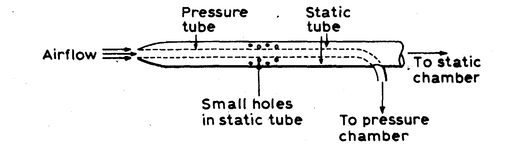
Concentric pitot – static head
Figure 8
The difference in pressure causes a deflection of the diaphragm or capsule, which, by suitable gearing, makes a pointer move round the scale, which is marked off in air speeds. Nowadays the pitot static tube may be connected across a pressure transducer, a device that gives an electrical signal proportional to the pressure difference.
VII. Manometers
Much quantitative work in experimental aerodynamics depends on the accurate measurement of pressure. An instrument which measures pressure is called a manometer. Strictly, it measures pressure difference, but if one of the two pressures is a standard, e.g., atmospheric, and is known, the other may be deduced immediately.
The simplest form of manometer is a simple U-tube, partly filled with a fluid of known density. The difference in fluid level between the two arms of the tube, to which the two pressure tappings are connected, gives directly the required pressure difference. Consider such a U-tube, mounted vertically, as shown in Figure 9. If h is the difference in fluid level, and ρ is the density of the fluid in the tube, then the pressure difference is
![]() ,
(3)
,
(3)
For water, ρ = 1000 kg/m3 and g = 9,81 m/s2, so that if h = 1 m, the corresponding pressure difference is 9810 N/m2. Thus a difference in fluid level of 1 cm is equivalent to a pressure difference of 98,1 N/m2. If the fluid in the manometer is not water, but has specific gravity γ, then the pressure difference corresponding to a difference in fluid level of 1 cm is 98,1*γ N/m2.
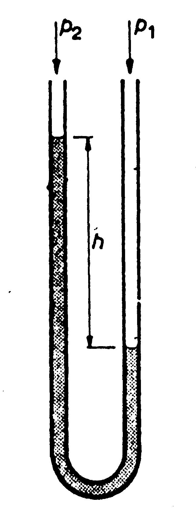
Figure 9
The use of a simple U-tube involves the measurement of two fluid levels. If one of the arms of the tube were very much wider than the other, then variation of pressure difference would result in very little change in level in the wider tube, compared with that in the other. The level of fluid in the wider tube might then be regarded as constant, and only the level in the narrow arm need be read. The vertical tube manometer consist of narrow vertical tube, backed by a graduated scale, communicating at the bottom with a wide reservoir of fluid.
Greater sensitivity can be obtained by inclining the tube to the vertical, so that for the same pressure difference there is a greater difference in fluid level measured along the tube. If the tube is inclined at an angle α to the vertical, a reading of 1 cm on the scale is equivalent to a pressure difference of 98,1 cos N/m2. A tube whose inclination may be varied gives variable sensitivity for different purposes. Such a device is an inclined tube manometer (Figure 10).
An inclined tube manometer
Figure 10
-
- the reservoir with fluid (F- area of cross – section of reservoir);
-
- the measuring inclined glass tube (f – area of tube cross - section);
-
- the filling plug;
-
- the regulator of zero line of fluid in the reservoir;
-
- the three – position tap.
During measurement of pressure difference an inclined tube manometer should be exposed strictly horizontal, for this purpose there are two levels in frame of an inclined tube manometer.
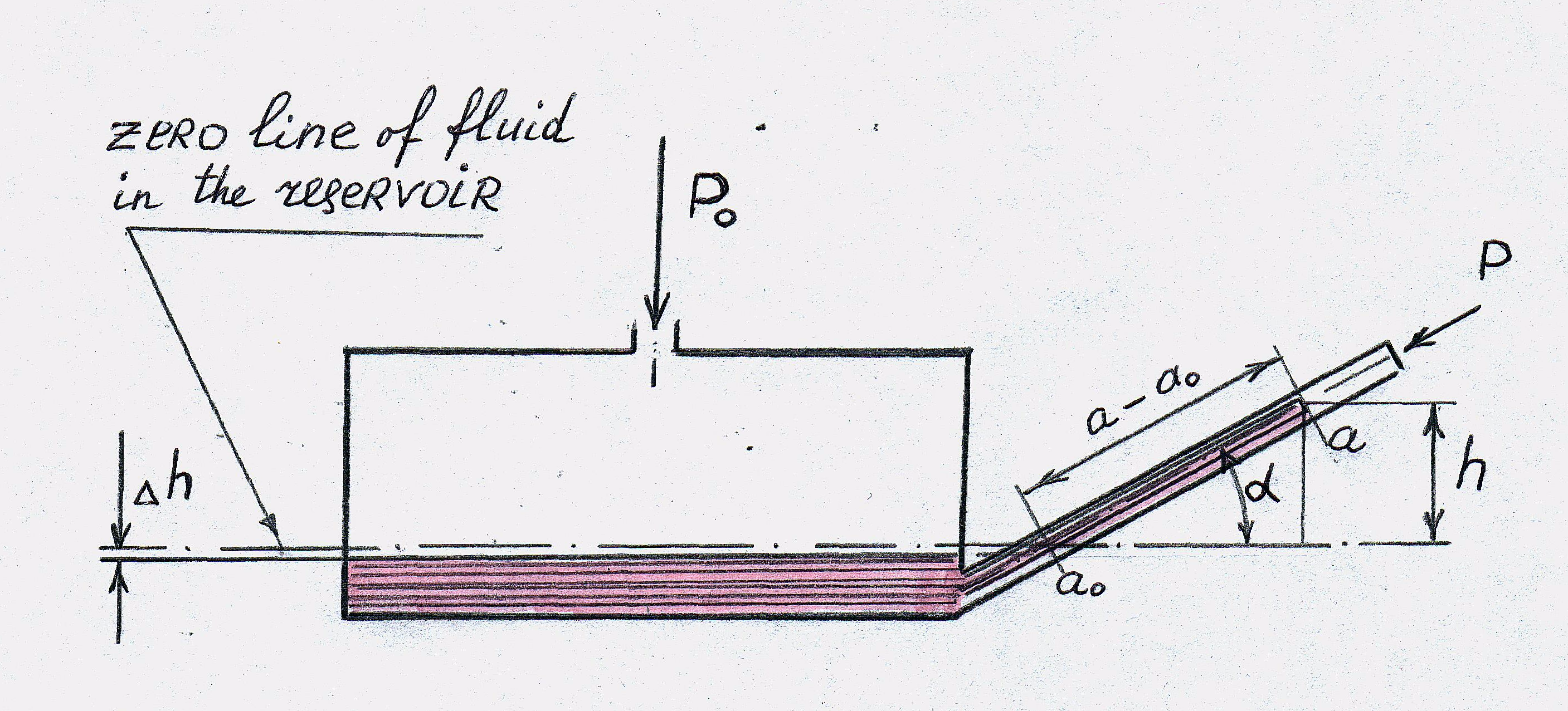
Figure 11
If
the
![]() -
pressure difference, the airspeed value will be
-
pressure difference, the airspeed value will be
![]() , (4)
, (4)
where
ρ – deusity of air.
According to Figure 11,
![]() or
or
![]() ,
(5)
,
(5)
but
![]() ,
where
,
where
![]()
If we enter the coefficient of manometre Km,
![]()
we
receive finally
![]() , (6)
, (6)
or
![]() ,
(7)
,
(7)
Where a large number of pressure measurements are to be made simultaneously, as in a pressure plotting experiment, it is convenient, rather than to record each pressure separately, to use a multi-tube manometer. Such an instrument consists of many similar, parallel tubes, side by side, communicating at the bottom with a common reservoir, and all backed by a graduated scale. The pressure differences between the various tappings, one of which is usually a standard, are then given by the differences in fluid levels in the various tubes. Again, the inclination of such a bank of tubes may be varied to give greater or less sensitivity. The sensitivity may also be greater or less according to the density of the fluid used, which may be water, or alcohol, say, and of relatively low specific gravity, or mercury, which is very dense. In the latter case, the sensitivity would be much less, but the range of pressures which could be measured would be much greater for a given length of tube. Most such instruments incorporate a clamp which can be closed over the rubber connecting tubes at the top of the manometer, to maintain the fluid levels after the conclusion of the tests in which the pressure differences are being measured. This enables the readings to be made at leisure, even when the wind tunnel has a short running time.