

Здания, сооружения и их устойчивость при пожаре / Европейские нормативные документы (Еврокоды) / DSTU-N B EN 1994-1-2 (Eurokod 4)
.pdfпрДСТУ-Н Б EN 1994-1-2:201Х
Додаток Е
(довідковий)
Модель для розрахунку несучої здатності при згині опорного та прольотного перерізів сталевої балки спільно з бетонною плитою, що зазнає вогневого впливу знизу
Рисунок E.1: Розрахунок несучої здатності прольотного перерізу на згин
E.1 Розрахунок несучої здатності прольотного перерізу на згин Mfj,Rd+
(1) Згідно з рисунком E.1 розтягуюча сила T+ та точку її прикладання yT можна визначити за формулами:
T+ = [( Fay,θ1 (B1E1 ) + Fay,θw (BwEw )+
+Fay,θ2 (B2E2 )] / γ M , fi,a ,
yT = [( fay,θ1 (b1 )(e12 / 2)+ fay,θw (hwew )(e1 + hw / 2) +
+ fay,θ2 (b2e2 )(h − e2 / 2)] /(T +γ M , fi,a ),
де fay,θ - максимальний рівень напруження згідно з розділом 3.2.1 за температури θ, визначеної згідно з 4.3.4.2.2.
(2) У вільно опертій балці значення розтягуючої сили T+, отримане з Е.1.1, обмежується:
T + ≤ NPFI ,RD ,
де N – мінімальне число стрижневих анкерів для будь-якої граничної довжини балки;
Pfi,Rd – розрахунковий опір стрижневого анкера на зсув під час пожежі
згідно з 4.3.4.2.5.
Примітка. Граничні довжини визначаються кінцевими опорами та поперечним перерізом з максимальним згинальним моментом.
Annex E
[informative]
Model for the calculation of the sagging and hogging moment resistances of a steel beam connected to a concrete slab and exposed to fire beneath the concrete slab.
Стиск
Розтяг
Figure E.1: Calculation of the sagging moment resistance
E.1 Calculation of the sagging moment resistance Mfj,Rd+
(1) According to Figure E.1 the tensile force T+ and its location yT may be obtained from:
(E.1)
(E.2) with fay,θ the maximum stress level
according to 3.2.1 at temperature θ defined following 4.3.4.2.2.
(2) In a simply supported beam, the value of the tensile force T+ obtained from (1) is limited by:
(E.3)
where:
N is the smaller number of shear connectors related to any critical length of the beam and
Pfi,Rd is the design shear resistance in the fire situation of a shear connector according
to 4.3.4.2.5.
NOTE: The critical lengths are defined by the end supports and the cross-section of maximum bending moment.
114
(3) Висота стиснутої зони hu визначається за формулою:
HU = T + /(BEFF FC / γ M , FI ,C ),
де beff – розрахункова ширина згідно з 5.4.1.2 EN 1994-1-1;
fc – міцність бетону на стиск за нормальної температури.
(4) Може бути розглянуто два випадки: (hc – hU) ≥ hcr
де hcr – відстань х за таблицею D.5, що відповідає температурі бетону нижче 250 °С. У цьому випадку використовується значення hu за рівнянням (Е.4).
або (hc – hU) < hcr; деякі шари стиснутої зони бетону мають
температуру, вищу за 250 °С. Зважаючи на це, може спостерігатися зниження міцності бетону на стиск згідно з 3.2.2. Значення hu можна визначити ітерацією, змінюючи індекс “n” та приймаючи середню температуру кожного шару товщиною 10 мм на основі таблиці D.5, наприклад:
|
|
|
N−1 |
|
T + = F = [(HC |
− HCR )(BEFF ) FC |
+ ∑(10BEFF |
) FC,θI + |
|
|
|
|
I=2 |
|
+ (HU ,NBEFF ) FC,θN ] / γ M , FI ,C , |
|
|
||
де H |
= (H |
− H ) +10(N − 2) + H |
, мм |
|
U |
C |
CR |
U ,N |
|
n – загальна кількість стиснутих шарів бетону, включаючи верхній шар бетону (hc – hcr) з температурою нижче 250 °С.
(5) Положення точки прикладення стискаючої сили визначена за формулою:
yF ≈ h + hC − (hU / 2) . Несуча здатність прольотного перерізу на згин:
M FI ,RD + = T + ( YF − YT ) ,
де Т+ – розтягуюча сила, визначена за формулою (Е.5), з урахуванням умови (Е.3).
(6) Ця розрахункова модель може застосовуватися для плити з профільованим сталевим настилом, за умови, що у формулах Е.1.3 та Е.1.4; hc замінено на
heff, як визначено в D.4.1, та hu обмежується значенням h1, як показано
на рисунках 4.1 та 4.2.
прДСТУ-Н Б EN 1994-1-2:201Х
(3) The thickness of the compressive zone hu is determined from:
(E.4) where beff is the effective width according
to 5.4.1.2 of EN 1994-1-1, and c f the compressive strength of concrete at room temperature.
(4) Two situations may occur:
with hcr is the depth x according to Table D.5 corresponding to a concrete temperature below 250°C. In that situation the value of hu according to equation (E.4) applies.
or some layers of the compressive zone of concrete are at a temperature higher than 250°C. In this respect, a decrease of the compressive strength of concrete may be considered according to 3.2.2. The hu value may be determined by iteration varying the index "n" and assuming on the basis of Table D.5 an average temperature for every slice of 10 mm thickness, such as:
(Е.5)
(E.5)
where:
[mm]
n is the total number of concrete layers in compression, including the top concrete layer (hc – hcr) with a temperature below 250°C.
(5) The point of application of this compression force is obtained from
(E.6) and the sagging moment resistance is
(E.7)
with T+, the tensile force given by the value of (E.5) while taking account of (E.3).
(6) This calculation model may be used for a composite slab with a profiled steel sheet,
provided in (3) and (4), hc is replaced by heff as defined in (1) of D.4 and hu is limited by
h1 as defined in Figures 4.1 and 4.2.
115
прДСТУ-Н Б EN 1994-1-2:201Х
(7) Дана розрахункова модель розроблена спільно з 4.3.4.2.4 та може бути використана для моделі критичної температури згідно з 4.3.4.2.3, припускаючи, що θ1=θw=θ2=θcr.
(8) Схожий підхід може застосовуватись, якщо нейтральна вісь проходить не в бетонній плиті, а в сталевій балці.
Е.2 Розрахунок несучої здатності опорного перерізу на згин Mfj,Rd- на проміжній опорі (або в защемленні)
(1)Розрахункова ширина плити на
проміжній опорі (або в защемленні) beff може бути визначена таким чином, щоб пластична нейтральна вісь не проходила в бетонній плиті, наприклад, плита розглядається з тріщиною крізь всю товщину. Ця розрахункова ширина не має бути більшою за таку, що визначається за нормальної температури згідно з 5.4.1.2 EN 1994-1-1.
(2)Поздовжні розтягнуті арматурні стрижні можуть бути прийняті з
пластичною межею текучості fsy,θs, де θs - температура в плиті на рівні розміщення арматурних стрижнів.
(3)Ці розділи припускають, що пластична нейтральна вісь проходить точно по межі розділення плити та сталевого перерізу. Подібний підхід можна застосовувати, якщо пластична нейтральна вісь проходить через поперечний переріз, змінивши відповідним чином формулу.
(4)Пластичний опір перерізу негативному згинальному моменту може визначатися з урахуванням епюри напружень на
рисунку E.2 для значень температури θ1, θ2, θw розрахованих згідно з 4.3.4.2.2.
(7) This calculation model established in connection to 4.3.4.2.4, may be used for the critical temperature model of 4.3.4.2.3 by assuming that θ1=θw=θ2=θcr.
(8) A similar approach may be used if the neutral axis is not inside the concrete slab but in the steel beam.
E.2 Calculation of the hogging moment resistance Mfj,Rd- at an intermediate support (or at a restraining support)
(1)The effective width of the slab at an intermediate support (or at the restraining
support) − beff may be determined so that the plastic neutral axis does not lie in the concrete slab, i.e. the slab is assumed to be cracked over its whole thickness. This effective width may not be larger than that determined at normal temperature, according to 5.4.1.2 of EN 1994-1-1.
(2)The longitudinal tensile reinforcing bars
may be assumed at the plastic yield fsy,θs where θs is the temperature in the slab, at the level where the reinforcing bars are located.
(3)The following clauses assume that the plastic neutral axis is located just at the interface between the slab and the steel section. A similar approach may be used if the plastic neutral axis is within the steel cross section, by changing the formulae accordingly.
(4)The hogging plastic moment resistance of the composite section may be determined by considering the stress diagram of Figure
E.2, with temperatures θ1, θ2, θw calculated according to 4.3.4.2.2.
116

Рисунок E.2: Розрахунок несучої здатності опорного перерізу при згині
(5) Несуча здатність опорного перерізу на згин визначається за формулою:
M |
+ = T − ( YT− − YF− ) , |
FI ,RD |
|
де Т- – загальне розтягуюче зусилля, що дорівнює стискальній силі F- у сталевому перерізі.
(6) Значення стискальної сили F в критичному поперечному перерізі плити в прольоті відповідно до E.1(2) може бути таким:
F ≤ N × PFI , RD −T − , де N – кількість стрижневих анкерів між критичним поперечним перерізом та
проміжною опорою (або защемленням);
Рfi,Rd – опір стрижневого анкера на зсув під час пожежі, як зазначено у 4.3.4.2.5.
(7) Попередні правила можуть використовуватися для поперечних перерізів класів 1 та 2 під час пожежі, для перерізів класів 3 та 4 застосовуються правила Е.2.8 та Е.2.9.
Примітка. Класифікація може бути зроблена згідно з 4.2.2 EN 1993-1-2.
(8) Якщо сталева стінка або нижня сталева полиця комбінованого перерізу належить до класу 3 під час пожежі, їх ширина може бути зменшена до розрахункового значення, пристосована з EN 1993-1-5, де fy та E відповідно замінені на fay,θ та Еа,θ.
(9) Якщо сталева стінка або нижня сталева полиця комбінованого сталевого перерізу належить до класу 4 під час пожежі, її опором можна знехтувати.
прДСТУ-Н Б EN 1994-1-2:201Х
Розтяг
Стиск
Figure E.2: Calculation of the hogging moment resistance
(5) The hogging moment resistance is given by:
where :
T− is the total tensile force of the reinforcing bars, equal to the compressive force F− in the steel section.
(6) The value of the compressive force F in the slab, at the critical cross section within the span, see (2) of E.1, may be such as:
(E.8)
where:
N is the number of shear connectors between the critical cross-section and the intermediate support (or the restraining
support) and where Рfi,Rd is the shear resistance of a shear connector in case of
fire, as mentioned in clause 4.3.4.2.5.
(7) The previous clauses may be used for cross sections of class 1 or 2 defined in the fire situation; for sections of class 3 or 4 the following clauses (8) to (9) apply.
NOTE: Classification may be done according to 4.2.2 of EN 1993-1-2.
(8) When the steel web or the lower steel flange of the composite section is of class 3 in the fire situation, its width may be reduced to an effective value adapted from EN 1993-1-5, where fy and E are respectively replaced by fay,θ and Еа,θ.
(9) When the steel web or the bottom steel flange of the composite section is of class 4 in the fire situation, its resistance may be neglected.
117

прДСТУ-Н Б EN 1994-1-2:201Х
E.3 Місцева стійкість на опорах
(1)Місцевий опір сталевого перерізу має перевірятися на дію реакції на опорі (або в защемленні).
(2)Температура ребра жорсткості θr розраховується з урахуванням коефіцієнта
поперечного перерізу Ar/Vr, згідно 4.3.4.2.2.
(3)Місцевий опір сталевого перерізу на опорі (або в защемленні) дорівнює меншому зі значень опорів поздовжньому згину або зминанню.
(4)Для розрахунку опору на поздовжній
згин максимальна ширина стінки 15εew з кожної сторони ребра жорсткості (рисунок Е.3), може враховуватися в робочому поперечному перерізі ребра.
Відносна гнучкість λθ , що використовується для розрахунку опору на поздовжній згин:
λθ = λ MAX{(KY ,θW / KE ,θW )0.5 ; (KY ,θR / KE ,θR )0.5 },
де kE,θ та ky,θ наведені в таблиці 3.2,
λ – відносна гнучкість ребра жорсткості разом з частиною стінки за нормальної температури, як показано на рисунку Е.3 та
ε – розраховується згідно з 4.2.2 EN 1993-1-2.
(5) Розрахунковий опір на зминання Rfi,y,Rd стінки з ребрами жорсткості:
R |
fi, y,Rd |
= [S |
s |
+ 5(E + R )]E |
w |
F |
θ |
w |
/ γ |
M , fi,a |
+ |
|
|
|
1 |
|
|
ay, |
|
|
|||||
+ Ar Fay,θr / γ M , fi,a , |
|
|
|
|
|
|
|
|
||||
де fay,θw |
та fay,θr |
– відповідно |
||||||||||
максимальні |
|
напруження |
|
сталі за |
||||||||
температури |
стінки |
θw |
|
та |
|
ребра |
||||||
жорсткості θr; |
|
|
|
|
|
|
|
|
|
|
||
r – |
радіус |
|
впадини |
гарячекатаного |
||||||||
профілю або A
 2 , де a – катет шва для звареного поперечного перерізу.
E.3 Local resistance at supports
(1)The local resistance of the steel section shall be checked against the reaction force at the support (or at the restraining support).
(2)The temperature of stiffener θr is calculated by considering its own section factor, Ar/Vr, according to 4.3.4.2.2.
(3)The local resistance of the steel section at the support (or at the restraining support) is taken equal to the lower value of the buckling or the crushing resistance.
(4)For the calculation of the buckling resistance a maximum width of the web of
15εew on each side of the stiffener (see Figure E.3) may be added to the effective cross section of the stiffener. The relative slenderness λθ , used to calculate buckling resistance is given by:
(E.9)
where:
kE,θ and ky,θ are given in Table 3.2,
λ is the relative slenderness at room temperature for the stiffener associated with part of web as shown in Figure E.3 and
ε is calculated according to 4.2.2 of EN1993-1-2.
(5) For the calculation of the crushing resistance, the design crushing resistance,
Rfi,y,Rd, of the web with the stiffeners is given by:
(E.10)
where:
fay,θw and fay,θr are respectively the maximum stresses in steel at the temperature
of web θw and of stiffener θr;
r is equal to the root radius for a hot
rolled section, or to A
 2 with a the throat of fillet weld for a welded cross-section.
118

прДСТУ-Н Б EN 1994-1-2:201Х
Стінка (θW)
Ребро жорсткості (θR)
Рисунок Е.3: Ребро жорсткості на проміжній опорі
Е.4 Розрахункове значення поперечної сили
(1) Умови, що наведені в 6.2.2 EN 1994-1-1, використовується для перевірки балки на дію поперечної сили під час пожежі
шляхом заміни Ea, fay та γa на Еа,θ, fay,θ та γM,fi,a відповідно, як визначено в таблиці 3.2 та пункті 2.3(1)Р.
Figure E.3: Stiffener on an intermediate support
E.4 Vertical shear resistance
(1) Clauses in 6.2.2 of EN 1994-1-1 may be used to check the vertical shear resistance of composite beams in fire situation by
replacing Ea, fay and γa by Еа,θ, fay,θ and γM,fi,a respectively as defined in Table 3.2 and
clause 2.3(1)P.
119

прДСТУ-Н Б EN 1994-1-2:201Х
Додаток F
(довідковий)
Модель для розрахунку несучої здатності на згин опорного та прольотного перерізів частково облицьованої сталевої балки спільно з бетонною плитою, що зазнає вогневого впливу знизу за стандартним температурним режимом
F.1 Зведений поперечний переріз для розрахунку несучої здатності прольотного перерізу на згин Mfj,Rd+
А – Приклад розподілу напруження в бетоні
Б – Приклад розподілу напруження в сталі
Рисунок F.1: Розрахункова схема для визначення несучої здатності прольотного перерізу на згин
(1) Переріз бетонної плити зменшено, як показано на рисунку F.1, але розрахункове значення міцності бетону
на стиск fc/γМ,fi,c не змінюється залежно від класів пожеж. Значення зменшення
товщини hc,fi бетонної плити наведені в таблиці F.1 для різних значень межі вогнестійкості.
Таблиця F.1: Зменшення товщини hc,fi бетонної плити
Annex F
[informative]
Model for the calculation of the sagging and hogging moment resistances of a partially encased steel beam connected to a concrete slab and exposed to fire beneath the concrete slab according to the standard temperature-time curve.
F.1 Reduced cross-section for sagging moment resistance Mfj,Rd+
Note to Figure F.1: (A) Example of stress distribution in concrete;
(B) Example of stress distribution in steel
Figure F.1:Calculation scheme for the sagging moment resistance.
(1) The section of the concrete slab is reduced as shown in Figure F.1, but the design value of the compressive concrete
strength fc/γМ,fi,c is not varying in function of the fire classes. The values of the thickness
reduction hc,fi of a flat concrete slab are given in Table F.1 for the different fire
classes.
Table F.1: Thickness reduction hc,fi of the concrete slab.
Нормована межа вогнестійкості |
Зменшення товщини плити hc,fi, мм |
Standard Fire Resistance |
Slab Reduction hc,fi [mm] |
R30 |
10 |
|
|
R60 |
20 |
|
|
R90 |
30 |
|
|
R120 |
40 |
|
|
R180 |
55 |
|
|
120
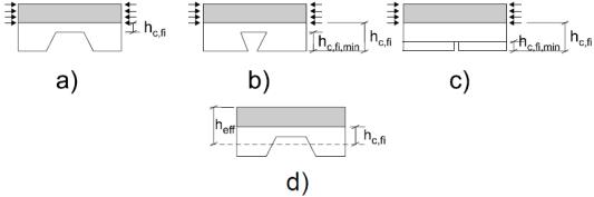
(2) Для інших систем бетонних плит застосовуються такі правила:
-для трапецеїдальних сталевих листів (рисунок 1.1), розташованих у поперечному до балки напрямку,
зменшення товщини hc,fi з таблиці F.1 може бути використано на верхній стороні сталевого настилу (рисунок F.2.a);
-для профілів зі вхідними кутами (рисунок 1.1), розташованих у поперечному до балки напрямку,
зменшення товщини hc,fi з таблиці F.1 може бути використано на нижній стороні сталевого настилу. Однак,
значення hc,fi не може бути менше ніж висота профілю настилу (рисунок F.2.б);
-для збірних залізобетонних настилів
зменшення товщини hc,fi з таблиці F.1 може бути використано на нижній стороні настилу, але не має бути меншою ніж висота зазору між збірними елементами, які не можуть передавати стискальні напруження (рисунок F.2.в);
-для профілів зі вхідними кутами, розташованих у поздовжньому до балки
напрямку, зменшення товщини hc,fi з таблиці F.1 може бути використано застосовується до нижньої сторони сталевого настилу;
-для трапецеїдальних сталевих листів, розміщених паралельно до балки,
зменшення товщини hc,fi з таблиці F.1 може бути використано для робочої
висоти плити heff (рисунок F.2.г), де робоча товщина плити heff вказана на рисунках 4.1 та у розділі D.4 додатку D.
Рисунок F.2: Зменшення товщини hc,fi для різних типів бетонних плит
(3) Температура θC шару бетону hc,fi, розташованого прямо над верхньою полицею, може дорівнювати 20 °C.
прДСТУ-Н Б EN 1994-1-2:201Х
(2) For other concrete slab systems the following rules apply:
-for trapezoidal steel sheets (see Figure 1.1) disposed transversally on the beam, the
thickness reduction hc,fi of Table F.1 may be applied on the upper face of the steel deck (Figure F.2.a);
-for re-entrant profiles (see Figure 1.1) disposed transversally on the beam, the
thickness reduction hc,fi of Table F.1 may be applied on the lower face of the steel deck.
However, the value of hc,fi may not be smaller than the height of the deck profile
(Figure F.2.b);
-when prefabricated concrete planks are
used, the thickness reduction hc,fi of Table F.1 may be applied on the lower face of the concrete plank, but may not be smaller than the height of the joint, between precast elements, unable to transmit a compression stress (Figure F.2.c);
-for re-entrant profiles parallel to the beam,
the thickness reduction hc,fi of Table F.1 applies on the lower face of the steel deck;
-for trapezoidal steel sheets parallel to the
beam, the thickness reduction hc,fi of Table F.1 may be applied on the effective height of
the slab heff (see Figure F.2.d), where the effective thickness of the slab heff is given in
Figures 4.1 and in D.4 of Annex D.
Figure F.2: Thickness reduction hc,fi for various types of concrete slabs
(3) The temperature θC of the concrete layer
hc,fi situated directly on top of the upper flange, may be assumed to be 20°C.
121
прДСТУ-Н Б EN 1994-1-2:201Х
(4) Робоча ширина верхньої полиці профілю (b-2bfі) змінюється залежно від різних значень межі вогнестійкості, але розрахункове значення границі текучості сталі дорівнює Значення зменшення ширини полиці bfi наведено в таблиці F.2 для різних значень межі вогнестійкості.
Таблиця F.2: Зменшення ширини bfi верхньої полиці
(4) The effective width of the upper flange of the profile (b-2bfі) varies as a function of the fire classes, but the design value of the yield point of the steel is taken equal to
fay/γМ,fi,a. The values of the flange width reduction fi b are given in Table F.2 for the
different fire classes.
Table F.2: Width reduction bfi of the upper flange
Нормована межа вогнестійкості |
Зменшення ширини bfi верхньої полиці, мм |
Standard Fire Resistance |
Width Reduction bfi of the Upper Flange [mm] |
|
|
R30 |
(ef/2) + (b-bc)/2 |
R60 |
(ef/2) + 10 + (b-bc)/2 |
R90 |
(ef/2) + 30 + (b-bс)/2 |
R120 |
(ef/2) + 40 + (b-bс)/2 |
R180 |
(ef/2) + 60 + (b-bc)/2 |
(5) Стінка розділена на дві частини: верхню висотою hh та нижню висотою hl. Значення hl визначені для різних значень межі вогнестійкості за формулою
hl = a1/bc + a2ew/(bc h). Параметри a1 та a2 наведені в таблиці F.3 для h/bc ≤ 1 або
h/bc ≥ 2.
Значення висоти нижньої частини hl наведено в таблиці F.3 для 1 < h/bc < 2.
Таблиця F.3: Висота нижньої частини
стінки hl, мм та hl,min, мм враховуючи, що hl,max становить (h-2ef)
(5) The web is divided into two parts, the top part hh and the bottom part hl. The values of hl are given for the different fire classes by the formula hl = a1/bc + a2ew/(bc h). Parameters a1 and a2 are given in Table F.3 for h / bc ≤ 1 or h / bc ≥ 2.
The bottom part hl is given directly in Table F.3 for 1 < h/bc < 2.
Table F.3: Bottom part of the web hl [mm] and hl,min [mm], with hl,max equal to (h-2ef).
|
Нормована межа вогнестійкості |
а1, мм2 |
а2, мм2 |
hl,min, мм |
|
|
|
|
|
|
R30 |
3600 |
0 |
20 |
|
|
|
|
|
|
R60 |
9500 |
20000 |
30 |
|
|
|
|
|
h/bc<1 |
R90 |
14000 |
160000 |
40 |
|
R 120 |
23000 |
180000 |
45 |
|
|
|
|
|
|
R 180 |
35000 |
400000 |
55 |
|
|
|
|
|
|
R30 |
3600 |
0 |
20 |
|
|
|
|
|
|
R60 |
9500 |
0 |
30 |
|
|
|
|
|
h/bc>2 |
R90 |
14000 |
75000 |
40 |
|
R 120 |
23000 |
110000 |
45 |
|
|
|
|
|
|
R 180 |
35000 |
250000 |
55 |
|
|
|
|
|
122
прДСТУ-Н Б EN 1994-1-2:201Х
|
R30 |
hl = 3600/bc |
20 |
|
R60 |
hl = 9500 bc + 20000 (ew/bc h) (2 - h/bc) |
30 |
1<h/bc<2 |
R90 |
hl = 14000/bc +75000 (ew/bc h) + |
40 |
|
|
+ 85000 (ew/bc h) (2-h/bc) |
|
|
|
|
|
|
R120 |
hl =23000/bc+110000 (ew/bc h) + |
45 |
|
|
+70000 (ew/bc h) (2 - h/bc) |
|
|
|
|
|
|
|
|
|
|
R180 |
hl = 35000 / bc + 250000 (ew / bc h) + |
55 |
|
|
+ 150000 (ew / bc h) (2 - h / bc ) |
|
|
|
|
(6)Значення висоти нижньої частини hl > hl,min, дано в таблиці F.3.
(7)Для верхньої частини hh стінки розрахункове значення межі текучості
сталі дорівнює fay/γМ,fi,a. Для нижньої частини hl розрахункове значення межі
текучості залежить від відстані x, виміряної від краю верхньої частини стінки (рисунок F.1). Знижене значення межі текучості для частини hl можна визначити за формулою:
Fay,x = Fay [1 − X(1 − Ka )/ Hl ],
де ka – коефіцієнт зменшення межі текучості нижньої полиці, даний в F.1.8. Це приводить до трапецеїдальної форми розподілу напружень в hl.
(8) Площа нижньої полиці сталевого профілю не змінюється. Її межа текучості зменшена завдяки коефіцієнту ka, даному в таблиці F.4. Коефіцієнт зменшення ka обмежений мінімальним та максимальним значеннями, даними в таблиці.
Таблиця F.4: Коефіцієнт зменшення ka межі текучості нижньої полиці,
де a0 = (0,018 ef + 0,7)
(6) The bottom part hl of the web may
always be larger or equal than hl,min given in Table F.3.
(7) For the top part hh of the web, the design value of the yield point of the steel is taken
equal to fay/γМ,fi,a. For the bottom part hl, the design value of the yield point depends on
the distance x measured from the end of the top part of the web (see Figure F.1). The reduced yield point in hl may be obtained from:
(F.1)
where:
ka is the reduction factor of the yield point of the lower flange given in (8). This leads to a trapezoidal form of the stress distribution in hl.
(8) The area of the lower flange of the steel profile is not modified. Its yield point is reduced by the factor ka given in Table F.4. The reduction factor ka is limited by the minimum and maximum values given in this table.
Table F.4: Reduction factor ka of the yield point of the lower flange,
with a0 = (0,018 ef + 0,7).
Нормована межа вогнестійкості |
Коефіцієнт зменшення, ka |
ka,min |
ka,max |
|
Standard Fire Resistance |
Reduction Factor |
|||
|
|
|||
R30 |
[(1,12) - (84/bc) + (h/22bc)]a0 |
0,5 |
0,8 |
|
|
|
|
|
|
R60 |
[(0,21)-(26/bc) + (h/24bc)]a0 |
0,12 |
0,4 |
|
|
|
|
|
|
R90 |
[(0,12)-(17/bc) + (h/38bc)]a0 |
0,06 |
0,12 |
|
|
|
|
|
|
R120 |
[(0,1)-(15/bc) + (h/40bc)]a0 |
0,05 |
0,10 |
|
|
|
|
|
|
R180 |
[(0,03)-(3/bc) + (h/50bc)]a0 |
0,03 |
0,06 |
|
|
|
|
|
123