

Здания, сооружения и их устойчивость при пожаре / Европейские нормативные документы (Еврокоды) / DSTU-N B EN 1992-1-2 (Eurokod 2)
.pdfпрДСТУ-Н Б EN 1992-1-2:201Х
ДОДАТОК B (довідковий) СПРОЩЕНІ МЕТОДИ РОЗРАХУНКУ
B.1 Метод ізотерми 500 0С
B.1.1 Принципи та сфера застосування
(1)Цей метод застосовується за стандартного температурного режиму та для будь-яких інших температурно часових режимів пожежі, що викликають подібні температурні поля в елементі під час вогневого впливу. Температурно часові режими пожежі, що не відповідають цьому критерію, потребують окремого всебічного аналізу, який враховує відповідну міцність бетону залежно від температури.
(2)Цей метод застосовується для мінімальної ширини поперечного перерізу, що наведена в таблиці В.1:
а) для стандартного температурного режиму залежно від класу вогнестійкості;
b) для параметричної пожежі з коефіцієнтом врахування отворів O≥0,14 м1/2 (додаток А EN 1991-1-2)
Таблиця В.1 – Мінімальна ширина поперечного перерізу залежно від класу вогнестійкості (для стандартного температурного режиму) та питоме пожежне навантаження (параметрична пожежа)
a) Клас вогнестійкісті.
ANNEX B (Informative)
Simplified calculation methods
B.1 500°C isotherm method
B.1.1 Principle and field of application
(1)This method is applicable to a standard fire exposure and any other time heat regimes, which cause similar temperature fields in the fire exposed member. Time heat regimes which do not comply with this criteria, require a separate comprehensive analysis which accounts for the relative strength of the concrete as a function of the temperature.
(2)This method is valid for minimum width of cross-section given in table B1:
a)for a standard fire exposure depending on the fire resistance
b)for a parametric fire exposure with an opening factor O≥0,14 м1/2 (see EN 1991-1-2 Annex A)
Table B1: Minimum width of cross-section as function of fire resistance (for standard fire exposure) and fire load density (for parametric fire exposure)
a) Fire resistance.
Клас вогнестійкісті |
|
|
R 60 |
|
R 90 |
|
R 120 |
R 180 |
R 240 |
|
||
Fire resistance |
|
|
|
|
|
|||||||
|
|
|
|
|
|
|
|
|
|
|||
Мінімальна ширина поперечного перерізу, мм |
90 |
|
120 |
|
160 |
200 |
280 |
|
||||
Minimum width of cross-section mm |
|
|
|
|||||||||
|
|
|
|
|
|
|
|
|||||
b) Питоме пожежне навантаження. |
b) Fire load density. |
|
|
|
||||||||
Питоме пожежне навантаження, МДж/м2 |
200 |
|
300 |
|
400 |
600 |
800 |
|
||||
Fire load density MJ/m2 |
|
|
|
|
|
|||||||
Мінімальна ширина поперечного перерізу, мм |
100 |
|
140 |
|
160 |
200 |
240 |
|
||||
Minimum width of cross-section mm |
|
|
|
|
||||||||
|
|
|
|
|
|
|
|
|
||||
(3) |
Спрощений |
метод |
розрахунку |
|
(3) The simplified calculation method |
|||||||
стосується |
загального |
зменшення розміру |
comprises a general reduction of the cross-section |
|||||||||
поперечного |
перерізу |
з |
врахуванням |
size with respect to a heat damaged zone at the |
||||||||
температурно пошкодженої зони поверхневого |
concrete surfaces. The thickness of the damaged |
|||||||||||
шару бетону. Товщина пошкодженого бетону |
concrete, а500, is made equal to the average depth |
|||||||||||
а500 відповідає середній глибині розташування |
of the 500 °C isotherm in the compression zone of |
|||||||||||
500 0С ізотерми в стисненій зоні поперечного |
the cross-section. |
|
|
|
|
|||||||
перерізу. |
|
|
|
|
|
|
|
|
|
|
|
|
(4) |
Пошкоджений |
бетон, |
наприклад, |
|
(4) Damaged |
concrete, i.e. concrete with |
||||||
|
|
|
|
|
|
|
|
|
|
|
85 |
|

прДСТУ-Н Б EN 1992-1-2:201Х
бетон за температури більше ніж 500 0С вважається таким, що не забезпечує несучу здатність елементу, тоді як приведений поперечний переріз зберігає свої початкові значення міцності та модуля пружності.
(5) Для прямокутної балки з тристороннім вогневим впливом робочий поперечний переріз повинен узгоджуватись з рисунком В.1.
В.1.2 Методика розрахунку залізобетонного поперечного перерізу, що піддається впливу згинального моменту та осьової сили
(1) На основі підходу за приведеним поперечним перерізом методика розрахунку опору залізобетонного поперечного перерізу конструкції під час пожежі може проводитись наступним чином:
(a)Визначають ізотерми 500 0С для вказаного вогневого впливу, за стандартного або параметричного температурного режиму пожежі;
(b)Визначають розрахункові ширину bfi
та висоту dfi відкиданням бетону за межами 500 0С ізотерми (рисунок В.1). Закруглені кути ізотерм можуть вважатись наближеними до справжніх форм ізотерм до прямокутної або квадратної, як показано на рисунку В.1
Т – розтяг
a) тристоронній вогневий вплив на розтягнуту зону
86
temperatures in excess of 500 °C, is assumed not to contribute to the load bearing capacity of the member, whilst the residual concrete cross-section retains its initial values of strength and modulus of elasticity.
(5) For a rectangular beam exposed to fire on three sides, the effective cross-section in the fire situation will be in accordance with Figure B1.
B.1.2 Design procedure of a reinforced concrete cross-section, exposed to bending moment and axial load
(1) On the basis of the above reduced crosssection approach, the procedure for calculating the resistance of a reinforced concrete crosssection in the fire situation may be carried out as follows:
(a)Determine the isotherm of 500°C for the specified fire exposure, standard fire or parametric fire;
(b)Determine a new width bfi and a new effective height dfi of the cross-section by excluding the concrete outside the 500 °C isotherm (see Figure B.1). The rounded corners of isotherms can be regarded by approximating the real form of the isotherm to a rectangle or a square, as indicated in Figure B.1
T -Tension
a) fire exposure on three sides with the tension zone exposed
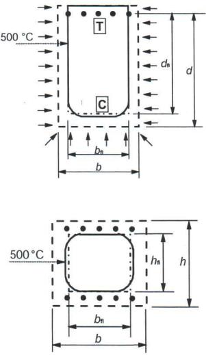
С – стиск
b) тристоронній вогневий вплив на стиснуту зону
c)чотирьохсторонній вогневий вплив (балка або колона)
Рисунок В.1 – Приведений поперечний переріз залізобетонної балки або колони
(c)Визначають температуру арматурних стрижнів в розтягнутій або стисненій зонах. Температуру окремо взятих арматурних стрижнів визначають за температурними кривими в додатку А або за довідковими даними приймають як температуру в центрі стрижня. Деякі з арматурних стрижнів можуть виходити за межі приведеного поперечного перерізу як зображено на рисунку В.1. Не зважаючи на це їх можна враховувати в розрахунку несучої здатності поперечного перерізу під час вогневого впливу;
(d)Визначають зменшену міцність арматури залежно від температури згідно з 4.2.4.3,
(e)Використовують конвекційний метод розрахунку для приведеного поперечного перерізу при визначенні критичної несучої здатності з міцністю арматурних стрижнів,
прДСТУ-Н Б EN 1992-1-2:201Х
C - Compression
b) fire exposure on three sides with the compression zone exposed
c) fire exposure on four sides (beam or column)
Figure B.1. Reduced cross-section of reinforced concrete beam and column
(c)Determine the temperature of reinforcing bars in the tension and compression zones. The temperature of the individual reinforcing bar can be evaluated from the temperature profiles in Annex A or handbooks and is taken as the temperature in the centre of the bar. Some of the reinforcing bars may fall outside the reduced cross-section, as shown in Figure B.1. Despite this, they may be included in the calculation of the ultimate loadbearing capacity of the fire exposed cross-section;
(d)Determine the reduced strength of the reinforcement due to the temperature according to 4.2.4.3,
(e)Use conventional calculation methods for the reduced cross-section for the determination of the ultimate load bearing capacity with strength of the reinforcing bars, as obtained in (d), and
87
прДСТУ-Н Б EN 1992-1-2:201Х
отриманої згідно з (d), та
(f) Порівнюють граничну несучу здатність з розрахунковим значенням навантаження або, як альтернатива, визначену вогнестійкість з нормованою.
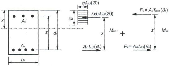
(2) Рисунок В.2 відображує розрахунок несучої здатності поперечного перерізу як з розтягнутим так і з стиснутим армуванням.
bfi |
ширина робочого поперечного перерізу |
||||
dfi |
розрахункова |
висота |
робочого |
||
поперечного перерізу |
|
|
|
||
z |
відстань між розтягнутою арматурою та |
||||
бетоном |
|
|
|
|
|
z* |
відстань між розтягнутою арматурою та |
||||
стиснутою арматурою |
|
|
|
||
As |
площа розтягнутої арматури |
|
|||
As1 |
частина |
розтягнутої |
арматури |
у |
|
рівновазі зі стисненим бетонним масивом |
|
||||
As2 |
частина |
розтягнутої |
арматури |
у |
|
рівновазі зі стиснутою арматурою |
|
||||
As’ |
площа стиснутої арматури |
|
|||
fcd,fi(20)=fck/γc,fi розрахункове значення опору бетону на стиск під час пожежі за нормальної температури
fsd,fi(θm) розрахункове значення опору арматури на розтяг під час пожежі за середньої температури θm в цьому ряді
розрахункове значення опору арматури на стиск під час пожежі за середньої температури θm в цьому ряді
Примітка. fsd,fi(θm) та fscd,fi(θm) може мати різні значення (див. 4.2.4.3)
F повне зусилля в стиснутій арматурі під час пожежі, та відповідне частині зусилля розтягнутої арматури
λ, η та х визначені в EN 1992-1-1
Рисунок В.2 – Розподіл напружень за критичної несучої здатності прямокутного залізобетонного перерізу зі стиснутим армуванням
88
(f) Compare the ultimate load-bearing capacity with the design load effect or, alternatively, the estimated fire resistance with the required resistance.
(2) Figure B.2 shows the calculation of loadbearing capacity of a cross-section with tension as well as compression reinforcement.
bfi is the width of effective cross-section
dfi is the effective depth of the effective crosssection
z |
is the lever arm between the tension |
reinforcement and concrete |
|
z* |
is the lever arm between the tension and |
compression reinforcement |
|
As |
is the area of tension reinforcement |
As1 |
is the part of tension reinforcement in |
equilibrium with the concrete compression block As2 is the part of tension reinforcement in equilibrium with the compression reinforcement As‘ is the area of compression reinforcement
fcd,fi(20)=fck/γc,fi is the design value of compression strength concrete in the fire situation at normal
temperature
fsd,fi(θm) is the design value of the tension reinforcement strength in the fire situation at
mean temperature θm in that layer
fscd,fi(θm) is the design value of the compression reinforcement strength in the fire situation at
mean temperature θm in that layer
Note: fsd,fi(θm) and fscd,fi(θm) may have different values (see 4.2.4.3)
F is the total force in compression reinforcement in the fire situation, and is equal to part of the total force in the tension reinforcement λ, η and x are defined in EN 1992-1-1
Figure B.2. Stress distribution at ultimate limit state for a rectangular concrete crosssection with compression reinforcement.

прДСТУ-Н Б EN 1992-1-2:201Х
(3)Якщо усі стиснуті стрижні розміщені
врядах і мають однакову площу, застосовуются наступні формули при розрахунку відстані до осі арматури а (див. рисунок В.2).
Середня знижена міцність арматурного ряду залежно від підвищених температур розраховується за формулою(В.1).
(3) If all reinforcement bars are positioned in layers and have the same area, the following expressions may be used in calculating the axis distance, a (see Figure B.2).
The average reduced strength of a reinforcement layer with respect to increased temperatures, is calculated in accordance with Expression (B.1).
kv(θ)= |
∑K (θI |
) |
(B.1) |
||
|
NV |
|
|||
|
|
|
|
|
|
де, |
|
|
|
|
where, |
θ – температура і-того арматурного |
|
|
θ is the temperature in reinforcement bar |
||
стрижня |
|
|
|
|
i |
k(θi) – коефіцієнт зниження міцності і- |
|
|
k(θi) is a reduction of the strength of the |
||
того арматурного стрижня залежно від |
|
|
reinforcement bar i due to the |
||
температури θi, як показано на |
|
|
temperature θi; which is obtained from |
||
рисунку 4.11 |
|
|
|
|
Figure 4.11 |
kv(θ) – середній коефіцієнт зниження |
|
|
kv(θ) is the average reduction of the |
||
міцності ν-того арматурного ряду |
|
|
|
|
strength of reinforcement layer ν |
nv – кількість арматурних стрижнів у ν |
|
|
nv is the number of reinforcement bars in |
||
-тому арматурному ряді |
|
|
|
|
layer ν |
(4) Відстань а від нижньої поверхні |
|
|
(4) The axis distance, a, from bottom |
||
робочого поперечного перерізу до центру |
|
surface of the effective cross-section to the |
|||
тяжіння арматурних рядів обчислюють за |
|
centroid of the reinforcement layers may be |
|||
формулою (B.2). |
|
|
|
calculated using Expression (B.2). |
|
a= |
∑AV KV (θ) |
|
(B.2) |
||
∑KV |
(θ) |
|
|||
|
|
|
|||
Де
av – відстань від нижньої поверхні робочого поперечного перерізу до осі v-того арматурного ряду
(5) Якщо існують тільки два ряди, відстань до осі арматури розраховується за формулою (B.3)
Where
av is the axis distance from the bottom surface of the effective cross-section to reinforcement layer
ν
(5) If only two layers exist the axis distance may be calculated using Expression (B.3)
|
|
|
|
|
|
|
(B.3) |
|
|
|
|
a= |
(A1A2 ) |
|
|
||
(6) Якщо арматурні стрижні мають різні |
|
(6) If the reinforcement bars have different |
||||||
площі |
та |
довільне |
розміщення |
areas and are distributed arbitrary the following |
||||
використовується наступна методика. |
procedure must be used. |
|||||||
Середній опір сталі арматурної групи |
|
The average steel strength of a |
||||||
k(φ)fsd,fi залежно від підвищених температур |
reinforcement group, k(φ)fsd,fi with respect to |
|||||||
розраховується за формулою (B.4) |
|
|
increased temperatures, may be calculated using |
|||||
|
|
|
|
|
Expression (B.4) |
|||
|
|
|
|
∑[KS (θI ) F SD ,I AI ] |
(B.4) |
|||
|
|
|
k(φ)fsd,fi= |
I |
|
|
|
|
|
|
|
|
∑AI |
||||
|
|
|
|
|
|
|||
|
|
|
|
|
I |
|
||
Де |
|
|
|
|
|
Where |
|
|
ks(θi) – коефіцієнт зниження міцності і- |
|
ks(θi) is a reduction of the strength of |
||||||
того арматурного стрижня |
|
|
|
reinforcement bar i |
||||
fsd,i |
– розрахунковий опір і-того |
|
fsd,i |
is the design strength of |
||||
арматурного стрижня |
|
|
|
reinforcement bar i |
||||
Ai – площа поперечного перерізу і-того |
|
Ai |
is the cross-section area of |
|||||
|
|
|
|
|
|
|
|
89 |
прДСТУ-Н Б EN 1992-1-2:201Х |
|
|
||
|
арматурного стрижня |
|
reinforcement bar i |
|
Відстань а (див. рисунок В.2) від нижньої |
The axis distance, a (see Figure B.2), from |
|||
поверхні робочого поперечного перерізу до |
the effective cross-section to the centroid of the |
|||
центру |
тяжіння |
арматурної |
групи |
reinforcement group is calculated in accordance |
розраховується за формулою (B.5). |
|
with Expression (B.5). |
||
|
∑[AI KS (θI ) FSD ,I AI ] |
(B.5) |
a= ∑[KS (θI ) FSD ,I AI ] |
||
|
I |
|
I
Де
ai – відстань від робочого поперечного перерізу до осі і-того арматурного стрижня
(7) Розрахунок згинального моменту поперечного перерізу виконується в наступній послідовності:
Where
ai is the axis distance from effective cross-section to reinforcement bar i
(7) The bending moment calculation of the cross-section is illustrated as follows:
Mu1=As1fsd,fi(θm)z |
(B.6) |
|||
ωk= |
AS1 F SD , FI (θM ) |
|
(B.7) |
|
B FI D FI FCD , FI (20) |
||||
|
|
|||
Mu2=As2fscd,fi(θm)z’ |
(B.8) |
|||
As=As1+As2 |
(B.9) |
|||
Де |
|
|
|
Where |
As – загальна площа армування |
|
As is the total reinforcement area |
||
fsd,fi – розрахунковий опір арматури на |
fsd,fi is the design tensile strength of |
|||
розтяг |
|
|
|
reinforcement |
fscd,fi – розрахунковий опір арматури на |
fscd,fi is the design strength for |
|||
стиск |
|
|
|
compressive reinforcement |
ωk – коефіцієнт міцності армування |
ωk is the design strength ratio of |
|||
поперечного |
перерізу |
під |
час |
reinforcement for the fire-exposed cross- |
вогневого впливу |
|
|
section |
|
bfi – ширина поперечного перерізу під |
bfi is the width of the fire exposed cross- |
|||
час вогневого впливу |
|
|
section |
|
dfi – робоча висота поперечного |
dfi is the efficient height of the fire |
|||
перерізу під час вогневого впливу |
|
exposed cross-section |
||
fcd,fi(20) – розрахунковий опір бетону |
fcd,fi(20) is the design compressive |
|||
на стиск (за нормальної температури) |
strength of concrete (at normal |
|||
|
|
|
|
temperature) |
z – відстань від розтягнутого |
z is the lever arm between tension |
|||
армування до бетону |
|
|
reinforcement and concrete |
|
z’ – відстань від розтягнутого до |
z’ is the lever between tension and |
|||
стиснутого армування |
|
|
compression reinforcement |
|
θm – середня температура арматурного |
θm is the mean temperature of the |
|||
ряду |
|
|
|
reinforcement layer |
Коли вплив моменту оцінюється як |
When the moment contributions are |
|||
показано вище, повна здатність чинити опір |
assessed as shown above the total moment |
|||
моменту обчислюється за формулою |
|
|
capacity is obtained from |
|
|
|
Mu=Mu1+Mu2 |
(B.10) |
|
B.2 Зональний метод |
|
|
B.2 Zone method |
|
(1) Метод поділу поперечного перерізу |
(1) The method of subdividing the cross- |
|||
на декілька зон наведено нижче. Цей метод, |
section into several zones is described below. This |
|||
хоч і більш трудомісткий, але більш точний |
method, although more laborious, provides a more |
|||
90 |
|
|
|
|
ніж метод 500 0С ізотерм, особливо для колон. Метод придатний тільки для стандартного температурного режиму.
(2)Поперечний переріз ділиться на декілька (n≥3) паралельних зон однакової товщини (прямокутні елементи), де враховується середня температура,
відповідний середній опір на стиск fcd(θ) та модуль пружності (якщо застосовується) кожної зони.
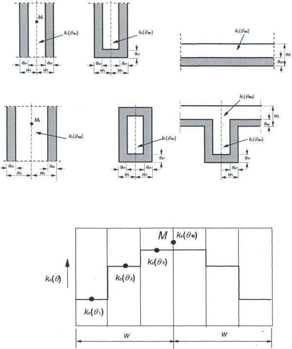
(3)Пошкоджений під час пожежі поперечний переріз представлений приведеним поперечним перерізом, який не
включає товщину пошкодженої зони az обігріваних поверхонь, див. рисунок В.3. Наводиться посилання на еквівалентну стіну (див. рисунки В.3(a) та В.3(d)). Точка М – довільна точка на центральній лінії еквівалентної стіни, якою користуються для визначення зменшеного опору на стиск всього приведеного поперечного перерізу. Коли дві протилежні сторони піддаються вогневому впливу ширина дорівнює 2w (див. рисунок В.3(a)). Для прямокутного поперечного перерізу тільки під час одностороннього вогневого впливу шириною вважається w (див. рисунок В.3(c)). Це представлено стіною з товщиною, що дорівнює 2w (див. рисунок В.3(d)). Полиця на рисунку В.3(f) відноситься до еквівалентної стіни на рисунку В.3(d), а стінка балки до еквівалентної стіни на рисунку В.3(a).
(4)Для нижньої частини та країв прямокутних елементів під час вогневого впливу, якщо ширина менше ніж висота,
значення az вважається таким як розрахункові значення для сторін, рисунки B.3 (b), (e), (f).
Приведення поперечного перерізу
базується на визначенні товщині az пошкодженої зони обігріваної поверхні:
(5)Пошкоджена зона az еквівалентної стіни під час двостороннього вогневого впливу розраховується наступним чином:
a) половина товщини стіни ділиться на n паралельних зон однакової товщини, де n≥3 (див. рисунок В.4);
b)температура розраховується для середини кожної зони;
c)визначається відповідний коефіцієнт
зниження міцності бетону на стиск kc(θi) в точці М (див. рисунок В.5).
прДСТУ-Н Б EN 1992-1-2:201Х
accurate method than the 500°C isotherm method especially for columns. The method is applicable to the standard temperature-time curve only.
(2)The cross-section is divided into a number (n≥3) of parallel zones of equal thickness (rectangular elements) where the mean temperature and the corresponding mean
compressive strength fcd(θ) and modulus of elasticity (if applicable) of each zone is assessed.
(3)The fire damaged cross-section is represented by a reduced cross-section ignoring a
damaged zone of thickness az at the fire exposed sides, see Figure B.3. Reference is made to an equivalent wall (see Figure B.3 (a) and (d)). The point M is an arbitrary point on the centreline of the equivalent wall used to determine the reduced compressive strength for the whole of the reduced cross section. When two opposite sides are exposed to fire the width is assumed to be 2w (see Figure B.3 (a)). For a rectangular cross-section exposed to fire on one face only, the width is assumed to be w (see Figure B.3 (c)). This is represented by a wall with a width equal to 2w (see Figure B.3 (d)). The flange of Figure B.3 (f) is related to the equivalent wall in Figure B.3 (d), and the web to the equivalent wall in Figure B.3
(a).
(4)For the bottom and ends of rectangular members exposed to fire, where the width is less than the height, the value of az is assumed to be the same as the calculated values for the sides, Figure B.3 (b), (e), (f).
The reduction of the cross-section is based
on a damaged zone of thickness az at the fire exposed surfaces which is calculated as follows:
(5)The damaged zone, az, is estimated as follows for an equivalent wall exposed on both sides:
a) The half thickness of the wall is divided into n parallel zones of equal thickness, where n ≥ 3 (see Figure B.4),
b) The temperature is calculated for the middle of each zone.
c) The corresponding reduction factor for
compressive strength, kc(θi) is determined (see Figure B.5).
91
прДСТУ-Н Б EN 1992-1-2:201Х
a) стіна |
b) край стіни |
c) плита |
a) (e.g wall) |
b) (e.g wall end) |
c) (e.g slab) |
d) товста стіна |
e)колона |
d) (e.g thick wall) |
e) (e.g column) |
Рисунок В.3 – Зниження міцності та приведення поперечного перерізу для частин під вогневим впливом
Рисунок В.4 – Поділ на зони стіни з двостороннім впливом вогню для розрахунку значень зниження міцності та az
(6) Середній коефіцієнт зниження міцності бетону в точці М для визначеної частини включаючи коефіцієнт (1-0,2/n), що враховує при розрахунку зміну температури кожної зони за формулою (B.11)
f) балка
f) (e.g beam)
Figure B.3. Reduction of strength and crosssection for sections exposed to fire
Figure B.4. Division of a wall, with both sides exposed to fire, into zones for use in calculation of strength reduction and aZ values
(6) The mean reduction coefficient for a particular section, incorporating a factor (1- 0,2/n) which allows for the variation in temperature within each zone, may be calculated by Expression (B.11)
kc,m= |
(1 − 0,2 / N) |
|
∑IN=1 KC (θI ) |
(B.11) |
|
N |
|||||
|
|
|
|||
де |
where |
|
|||
n – кількість паралельних зон в ширині |
n is the number of parallel zones in width |
||||
w |
w |
|
|||
92
прДСТУ-Н Б EN 1992-1-2:201Х
w – половина повної ширини m – кількість зон
(7) Ширину пошкодженої зони балок, плит або окремих конструкцій в площіні зрізу розраховують за формулою
w is half the total width m is the zone number
(7) The width of the damaged zone for beams, slabs or members in plane shear may be calculated using Expression
|
− |
KC,M |
|
(B.12) |
az= W 1 |
|
|
||
|
||||
|
|
KC (θM ) |
|
|
Де kc(θM) – коефіцієнт зниження міцності бетону на стиск в точці М.
(8)Для колон, стін та інших конструкцій,
вяких має місце впливи другого порядку, визначають за формулою (B.13).
Where kc(θM) denotes the reduction coefficient for concrete at point M.
(8) For columns, walls and other constructions where second order effects may be calculated using Expression (B.13).
|
|
|
|
K |
|
|
|
1,3 |
|
|
|
|
|
|
|
|
|
(B.13) |
|||
|
|
|
|
C,M |
|
|
|
|||
|
|
|
|
|
|
|||||
|
|
az= W 1 |
− |
|
|
|
|
|
|
|
|
|
|
|
KC (θM ) |
|
|
|
|||
|
|
|
|
|
|
|
|
|
|
|
(9) Коли приведений поперечний переріз |
|
|
|
|
|
|
(9) When the reduced cross-section is found |
|||
знайдено, а міцність та модуль пружності |
|
|
and the strength and modulus of elasticity are |
|||||||
бетону під час пожежі визначено, розрахунок |
|
|
determined for the fire situation, the fire design |
|||||||
на вогнестійкість виконують за методикою |
|
|
follows the normal temperature design procedure |
|||||||
розрахунку |
за нормальних температур, |
|
|
similar to that shown in Figure B.2 by using γM,fi |
||||||
подібної до тої, що відображена на рисунку |
|
|
values. |
|||||||
В.2 з використанням значень γM,fi. |
|
|
|
|
|
|
|
|
||
B.3 |
Розрахунок |
залізобетонного |
|
|
|
|
|
|
B.3 Assessment of a reinforced concrete |
|
поперечного перерізу під дією згинального |
|
|
cross-section exposed to bending moment and |
|||||||
моменту та поздовжньої сили за методом на |
|
|
axial load by the method based on estimation |
|||||||
основі оцінки кривизни. |
|
|
|
|
of curvature. |
|||||
B.3.1 Поздовжній згин колони під час |
|
|
|
|
|
|
B.3.1 Buckling of columns under fire |
|||
пожежі |
|
|
|
|
|
conditions |
||||
(1) Цей пункт стосується колон, робота |
|
|
|
|
|
|
(1) This clause deals with columns in which |
|||
яких зазнає значних впливів другого порядку |
|
|
the structural behaviour is significantly influenced |
|||||||
під час пожежі. |
|
|
|
|
by second order effects under fire conditions. |
|||||
(2) Під час пожежі пошкодження верхніх |
|
|
|
|
|
|
(2) Under fire conditions, the damage of the |
|||
шарів елемента через високі температури в |
|
|
outer layers of the member due to high |
|||||||
сполученні з різким зниженням модуля |
|
|
temperatures, combined with the drop of the |
|||||||
пружності у внутрішніх шарах приводить до |
|
|
elasticity modulus at the inner layers, results in a |
|||||||
зниження стійкості елементів конструкцій під |
|
|
decrease of the stiffness of structural members |
|||||||
час пожежі. Через це впливи другого порядку |
|
|
under fire conditions. Because of this, second |
|||||||
можуть бути значними для колон під час |
|
|
order effects can be significant for columns in the |
|||||||
пожежі, хоча за температури навколишнього |
|
|
fire situation although at ambient temperature |
|||||||
середовища їх дія майже не помітна. |
|
|
|
conditions their effect is negligible. |
||||||
(3) Оцінка колони під час пожежі як |
|
|
|
|
|
|
(3) The assessment of a column under fire |
|||
окремого елементу може виконуватись за |
|
|
conditions as an isolated member may be made by |
|||||||
методом на основі оцінки кривизни (розділ 5 |
|
|
using a method based on the estimation of |
|||||||
EN 1992-1), якщо можна застосовувати |
|
|
curvature (see Section 5 of EN 1992-1) if the |
|||||||
наступні правила. |
|
|
|
|
following rules are applied. |
|||||
w, мм (mm)
93

прДСТУ-Н Б EN 1992-1-2:201Х
хв
хв
хв
хв
хв
хв
w – визначається як: w is assessed as:
-товщина плити,
-The thickness of a slab,
-товщина стіни та колони з одностороннім вогневим – впливом,
-половина товщини стінки балки,
-The thickness of a one sided exposed wall or column,
-половина товщини колони або стіни з двостороннім вогневим впливом або
-Half the thickness of the web of a beam,
-Half the thickness of a two sided exposed wall or column or
-половина найменшого значення колони з чотирьохстороннім впливом.
-Half the smallest dimension of a four sided exposed column.
a) Зниження міцності на стиск бетону на силікатному заповнювачі приведеного поперечного перерізу.
a) Reduction of compression strength for a reduced cross-section using siliceous aggregate concrete.
t, хв
t, хв
w, мм |
w in mm |
б) Приведення поперечного перерізу az балки з бетону на силікатному заповнювачі
b) Reduction in cross-section az, of a beam or slab using siliceous aggregate concrete.
Примітка: Значення для бетону на силікатному заповнювачі застосовують для більшості інших заповнювачів
w, мм w in mm
c) Приведення поперечного перерізу
az колони або стіни з бетону на силікатному заповнювачі
c) Reduction in cross section az, of a column or wall using siliceous aggregate concrete.
Note: The value for siliceous aggregate concrete are conservative for most other aggregates
Рисунок В.5 – Приведення поперечного перерізу та зниження міцності бетону за стандартним температурним режимом
(4) Для будівель із в’язями жорсткості непрямий вогневий вплив може не враховуватись, якщо зменшення моментів
Figure B.5: Reduction in cross section and concrete strength assuming standard temperaturetime curve
(4) For braced building structures, indirect fire actions need not be considered if the decrease of the first order moments due to the decrease of
94