

Maxwell_v16_L03_Static_Magnetic_Solvers
.pdfLecture 3:
Static Magnetic Solvers
ANSYS Maxwell V16
Training Manual

 Content
A.Magnetostatic Solver
a.Selecting the Magnetostatic Solver
b.Material Definition
c.Boundary Conditions
d.Excitations
e.Parameters
f.Analysis Setup
g.Solution Process
B.Eddy Current Solver
a.Selecting the Eddy Current Solver
b.Material Definition
c.Boundary Conditions
d.Excitations
e.Parameters
f.Analysis Setup
g.Solution Process
© 2013 ANSYS, Inc. |
May 21, 2013 |
2 |
Release 14.5 |
 A. Magnetostatic Solver
Magnetostatic Solver
–In the Magnetostatic Solver, a static magnetic field is solved resulting from a DC current flowing through a coil or due to a permanent magnet
–The Electric field inside the current carrying coil is completely decoupled from magnetic field
–Losses are only due to Ohmic losses in current carrying conductors
–The Magnetostatic solver utilizes an automatic adaptive mesh refinement technique to achieve an accurate and efficient mesh required to meet defined accuracy level (energy error).
Magnetostatic Equations
– Following two Maxwell’s equations are solved with Magnetostatic solver
H J
B 0
B μ ( H M ) |
|
H |
M p |
|
0 |
0 |
r |
0 |
|
Maxwell 3D
J |
|
1 |
|
|
|
( x, y) |
|
|
( A ( x, y)) |
||
z |
|
|
z |
|
|
|
|
||||
|
0 |
r |
|
||
Maxwell 2D
© 2013 ANSYS, Inc. |
May 21, 2013 |
3 |
Release 14.5 |
 a. Selecting the Magnetostatic Problem
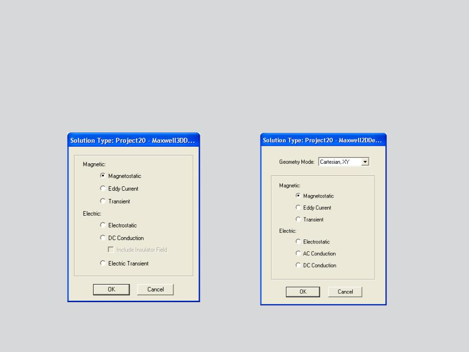
Selecting the Magnetostatic Solver
–By default, any newly created design will be set as a Magnetostatic problem
–Specify the Magnetostatic Solver by selecting the menu item Maxwell 2D/3D
Solution Type
–In Solution type window, select Magnetic> Magnetostatic and press OK
Maxwell 3D |
Maxwell 2D |
© 2013 ANSYS, Inc. |
May 21, 2013 |
4 |
Release 14.5 |
 b. Material Definition
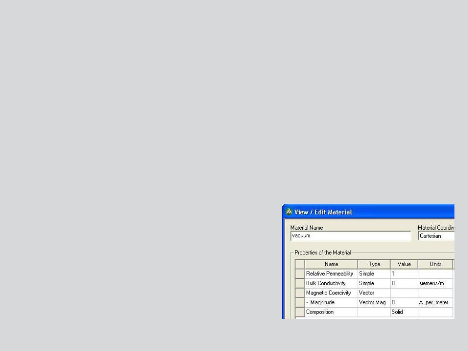
Magnetostatic Material Properties
–In a Magnetostatic simulation, the following parameters may be defined for a material (by clicking on the pull-down menu under Type and Value)
Relative Permeability:
•Permeability (µ) is defined as µ0*µr
•Relative permeability(µr) along with the Magnetic Coercivity determine the magnetic properties of the material.
•Relative permeability can be Simple(linear µr) or Nonlinear(BH Curve) or/and anisotropic
Bulk Conductivity:
•Used to determine the current distribution in current carrying conductors
•Does not have any impact on magnetic part of analysis
•Can be Simple or Anisotropic
Magnetic Coercivity:
•Used to define permanent magnetization of magnetic materials.
•Requires magnitude and direction specification.
•Direction specified is with respect to Orientation CS
of bodies to which material is assigned
Composition:
•Can be Solid or Lamination
•Setting Composition to Lamination creates an anisotropic magnetization effect.
© 2013 ANSYS, Inc. |
May 21, 2013 |
5 |
Release 14.5 |
 c. Boundary Conditions
Assigning Boundary Conditions in 3D
–Boundary conditions define behavior of the magnetic field at the interfaces or the edges of the problem region
–A boundary can be assigned to a face from menu item Maxwell 3D Boundaries Assign and select the required boundary assignment
Boundary Types(3D)
Default (No Boundary Assigned):
When no boundary is specified for a surface, following two treatments are assigned based on the surface position
•Natural: for the boundaries on the interface between objects. H Field is continuous across the boundary.
•Neumann: For exterior boundaries of solution domain. H Field is tangential to the boundary and flux cannot cross it.
H Vectors
Neumann |
Natural |
|
© 2013 ANSYS, Inc. |
May 21, 2013 |
6 |
Release 14.5 |
 …Boundary Conditions
Boundary Types (3D)
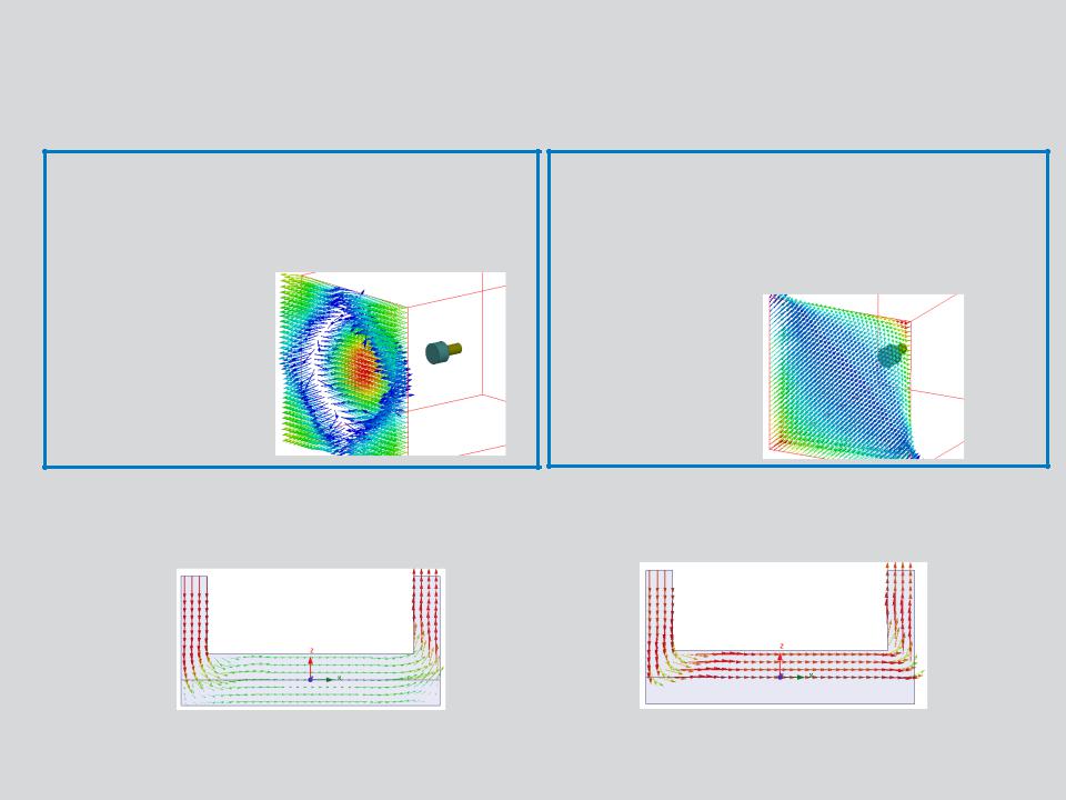
Zero Tangential H-Field:
•Useful to assign external field.
•H field is normal to assigned surface
•Can be applied to external boundaries of the domain
H Vectors on Zero Tangential H field boundary
Tangential H-Field:
•Useful to assign external field.
•Tangential H field is applied using U and V components
•Can be applied to external boundaries of the domain
H Vectors on Tangential H field boundary
Insulating:
•Same as Neumann, except that current cannot cross the boundary.
•Can be used to insulate two conductors which are in contact with each other
J Vectors without insulating |
J Vectors with insulating boundary |
boundary between plates |
defined between plates |
© 2013 ANSYS, Inc. |
May 21, 2013 |
7 |
Release 14.5 |
 …Boundary Conditions
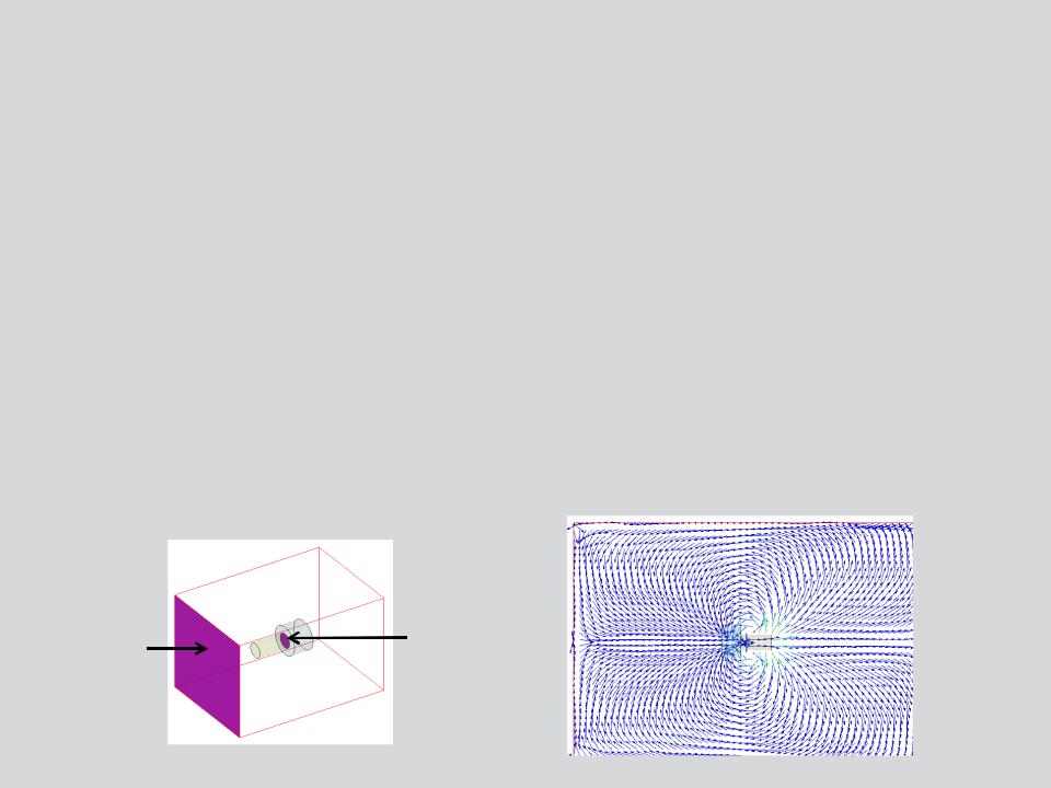
Boundary Types (2D)
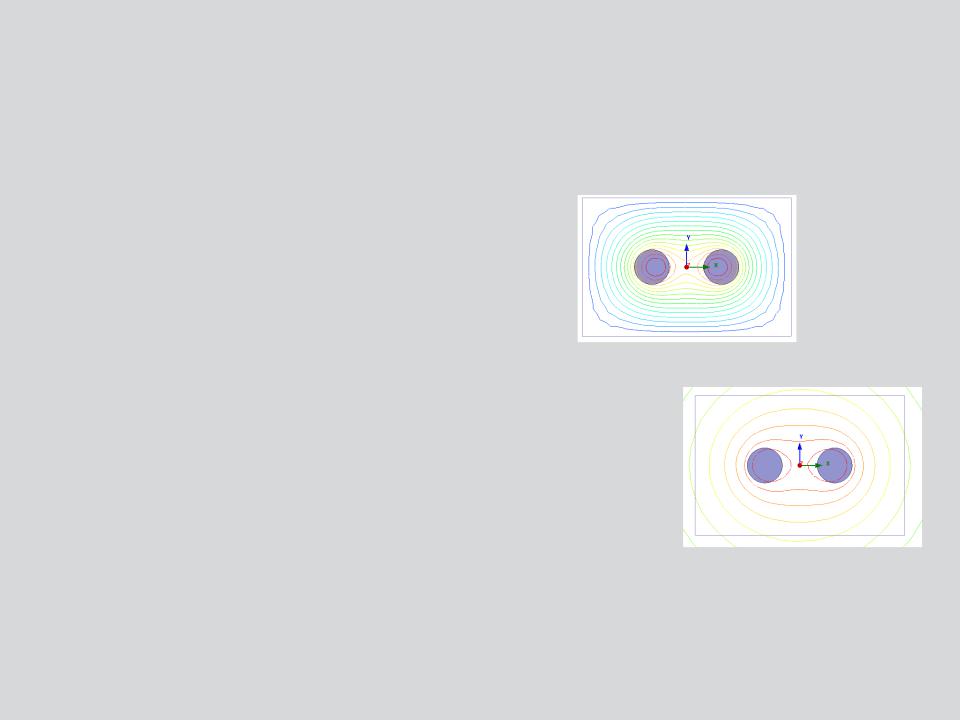
Vector Potential:
•Sets the specified value of magnetic vector potential on the boundary.
•Used to model Magnetically isolated structures.
Flux lines with zero vector potential on outer boundary
Balloon:
•Models the region outside drawing space as being infinitely large.
•Magnetic flux lines are neither tangential nor normal to the boundary
Flux lines with Balloon on outer boundary
Note: In 2D, no default boundary is assigned to the boundaries of the simulation region. Users have to specify the behavior of simulation boundaries by assigning either Balloon or vector potential boundary.
© 2013 ANSYS, Inc. |
May 21, 2013 |
8 |
Release 14.5 |
 …Boundary Conditions
Boundary Types (2D & 3D):
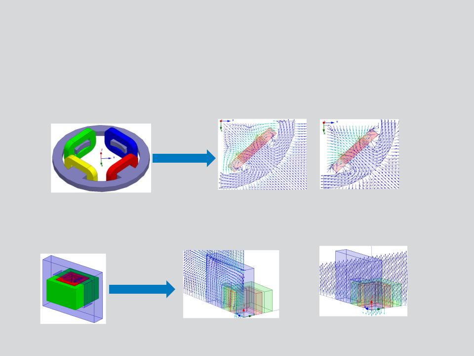
Master/Slave :
•Enable users to model only one period of a periodic structure, which reduces the design size
•This boundary condition matches the magnetic field at the slave boundary to the field at the master boundary based on U and V vectors defined.
1/4th Model
Master = Slave |
Master = -Slave |
Symmetry Boundary:
•Enable users to model only part of a structure, which reduces the size or complexity of design, thereby shortening the solution time.
•Applied to external boundaries of domain.
1/8th Model
Symmetry Odd: Same as default
Boundary (Flux Tangential)
Symmetry Even: Same as Zero Tangential H-Field boundary (Flux Normal)
© 2013 ANSYS, Inc. |
May 21, 2013 |
9 |
Release 14.5 |
 d. Excitations
Assigning Excitations
–Excitations can be assigned from the menu item Maxwell 2D/3D Excitations
Assign
Excitation (2D & 3D)
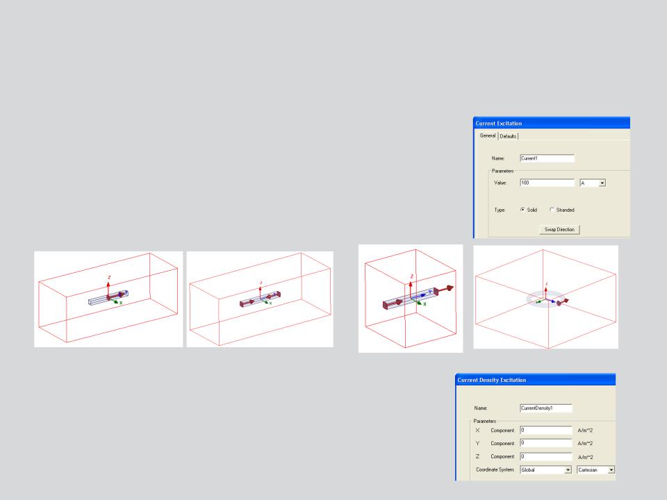
Current :
•Defines total current in Amp-turns through the conductor
•Can be assigned to the conductor faces that lie on boundary of simulation domain or sheets that lie completely inside the conductor
•Conductor can be defined as Solid or Stranded
Incorrect Excitation definitions |
|
Correctly defined Excitations |
Current Density:
•Used to define a known current density throughout an object.
•In 3D, this definition should be accompanied with Current Density Terminal definition
•Current Density defined using X,Y and Z components of selected CS
© 2013 ANSYS, Inc. |
May 21, 2013 |
10 |
Release 14.5 |