

11.1.2. Application
Consider an example. By the process control system connected transducers. This converter is located in hazardous areas. However, engineers did not take into account this fact and designed the system for normal conditions. Possible consequences of such misuse of the technical solution shown in Fig. 1 - 45:
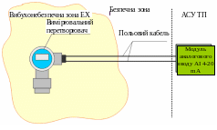
Fig. 1 - 45. The solution, which does not provide the necessary level of explosion
Faulty transmitter or arcing field cable can cause an explosion.
Given the requirements for explosion protection, the system must be constructed, as schematically shown in Fig. 1 - 46. Since the measuring transducer itself is in the danger zone, it is placed in the Flameproof (explosion protection type "d '). But as seen from the previous example, this is not enough. It is equally important to provide intrinsically safe electrical (signal) circuit connecting the converter and analog input module.
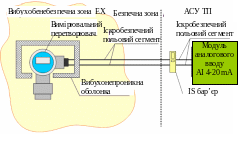
Fig. 1 - 46. Correct solution from the point of view of explosion protection
Now the system is designed correctly. Malfunction of the converter does not create an explosion, as a solid shell, which is placed the field transducer is holding the flash and makes it spread beyond the shell. Also now taken into account that as a result of short circuit, poor contact or actuation of the switching may arcing or invalid heating unprotected conductor. This is taken care of in advance, setting in a secure area of special electronic device called a barrier of intrinsically safe (IS barrier). The very name of this device makes it clear that his main purpose - is to ensure the protection of connected to it by the method of electric circuit "intrinsically safe circuit".
11.1.3. Spark Safety Barriers
In the minimum configuration is a barrier terminal blocks, which connect two electrical circuits. One chain forms the so-called spark dangerous (unprotected) segment, the other - intrinsically safe (protected). By unprotected segments comprise an electric line connecting the barrier with the corresponding input or output I / O modules. Intrinsically segment runs directly through the volatile area and connects the barrier with the field device. It is extremely important to remember that although the barrier and provide flame proof chain connected to it, it is not a safety explosion device and its installation in hazardous areas under any circumstances is unacceptable.
Typical diagram of the connection of barrier is shown in Fig. 1 - 47.

Fig. 1 - 47. Diagram of the connection of spark safety barrier
This picture shows the wiring diagram of the measuring converter with current output to the analog input module AI 4-20 mA via an intermediate barrier. The chain connecting the output of the converter and the entrance barrier is an intrinsically safe segment (often referred to the reduction of the word Ex Explosive). The chain of barrier between the exit and entrance to the analog input module creates unprotected segment.
What is the principle of the barrier? Experimentally that for the ignition of an explosive mixture of her need to pass certain energy Q. If the energy of an electric current is less than the maximum allowable Q, it is guaranteed that the explosion did not happen even in the event of a spark. On this principle and built work of intrinsic safety barrier. Naturally, the energy directly control difficult, but you can limit the power of an electric current flowing through the electrical circuit. Indeed, this problem of the barrier and is - he is continually monitoring and limits the power of the electric current flowing in the protected segment of the chain.
Power depends on the current and voltage and is determined by the formula:
P = UI.
The barrier adjusts current and voltage so that the power P will never exceed a certain maximum permissible value of R:
P <P.
So if, for any reason, the current in the protected segment of the chain will grow and with it the power, the barrier will reduce the applied voltage to ensure that the resulting output electrical signal less than Ppred. In fact, certain restrictions apply not only to power, but also on the maximum current and voltage. Strictly speaking, the barrier is monitored to always performed once three conditions are met:
P <P;
I <I;
U <U.
What are the barriers? Barriers are of two types: passive and active. Passive barriers are based on rather simple electronic circuits with zener, or Zener diodes. Their distinguishing feature is the lack of necessary utilities available to them an external power supply, but they require very careful grounding. Passive barriers are primarily used to connect the active field devices requiring a separate power supply. Active barriers - more functional devices, and, in terms of circuit design, the design of their somewhat more complicated. Due to the presence in them of the transformer and the amplifier stage, active barriers shall galvanic isolation between connected thereto spark-safe and vulnerable segments of the chain. Active barriers require an external power supply (usually from 24 VDC) and serve to connect the passive field devices, which feed directly on the signal chain.
Barriers are distinguished by the type of the connected thereto signal input / output. It traces the complete analogy with the I / O modules. In the examples above, we considered the measuring transducer with 4-20 mA. To connect it to the control system requires a barrier analog input AI in the range of 4-20 mA. For example, if you want to organize a discrete output DO relay type, the corresponding barrier is intended to support a discrete output DO relay type. The following types of barriers: DI (discrete input), DO (discrete output), AI (analog input) and AO (analog output).
Some models of active barriers can also carry out the transformation of the field signal from one type to another. For example, there are specific barriers for intrinsically safe connection of sensors such as "thermal resistance" (RTD), but the output of such barriers - is a standard 4-20 mA current. Thus, these barriers can be connected to conventional input modules AI 4-20 mA (remember that the RTD sensors do not transmit current signal).
Barriers also different channel, ie number of signal circuits, for which the barrier can implement INDICATORS. The most common one-and two-channel barriers. For example, a dual-barrier AI2 4-20 mA can simultaneously connect two sensors with current output 4-20 mA.
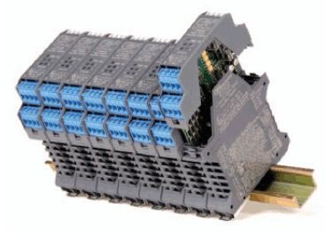
Fig. 1 - 48. Intrinsic Safety Barriers of GM International company