

plc timers - 9.21
Solution:
|
|
|
|
|
|
|
A |
|
|
TON |
T4:0 |
|
|
||||
|
|
|
|
Time base: 1.0 |
|
|
|
|
|
||
|
|
|
|
Preset 15 |
|
|
|
|
|
||
|
T4:0/DN |
Light |
|
||
|
|
|
|
|
|
|
|
|
|
|
|
|
|
|
|
|
|
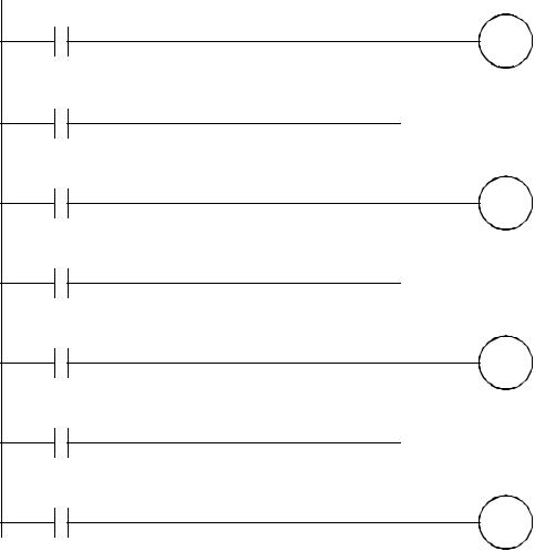
Figure 9.21 A Simple Timer Example
Problem: Develop the ladder logic that will turn on a light, after switch A has been closed 10 times. Push button B will reset the counters.
Solution:
A |
CTU |
C5:0 |
|
|
|
|
|
|
|
Preset 10 |
|
|
|
|
|
|
|
Accum. 0 |
|
|
|
|
|
C5:0/DN |
Light |
|
|
|
|
|
|
|
|
|
|
B
C5:0 RES
Figure 9.22 A Simple Counter Example
9.7.2 More Timers And Counters
Problem: Develop a program that will latch on an output B 20 seconds after input A has been turned on. After A is pushed, there will be a 10 second delay until A can have any effect again. After A has been pushed 3 times, B will be turned off.
Solution:
A
On
T4:0/DN
T4:0/DN
T4:1/DN
On
C5:0/DN
plc timers - 9.22
On |
L |
|
|
|
|
TON |
T4:0 |
Time base: 1.0 |
|
Preset 20 |
|
|
|
Light |
L |
|
|
|
|
TON |
T4:1 |
Time base: 1.0 |
|
Preset 10 |
|
|
|
On |
U |
|
|
|
|
CTU |
C5:0 |
Preset 3 |
|
Accum. 0 |
|
|
|
Light U
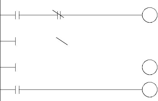
Figure 9.23 A More Complex Timer Counter Example
9.7.3 Deadman Switch
Problem: A motor will be controlled by two switches. The Go switch will start the motor and the Stop switch will stop it. If the Stop switch was used to stop the motor, the Go switch must be thrown twice to start the motor. When the motor is active a light should be turned on. The Stop switch will be wired as normally closed.
plc timers - 9.23
Solution:
Motor |
Stop |
C5:0
RES
Go |
|
Motor |
CTU |
C5:0 |
||
|
|
|
|
|
Preset 2 |
|
|
|
|
|
|
|
|
|
|
|
|
|
Accum. 1 |
|
|
|
|
|
|
|
|
C5:0/DN |
Stop |
Motor |
|
|||
|
|
|
|
|
|
|
|
|
|
|
|
|
|
Motor
Light
Consider:
- what will happen if stop is pushed and the motor is not running?
Figure 9.24 A Motor Starter Example
9.7.4 Conveyor
Problem: A conveyor is run by switching on or off a motor. We are positioning parts on the conveyor with an optical detector. When the optical sensor goes on, we want to wait 1.5 seconds, and then stop the conveyor. After a delay of 2 seconds the conveyor will start again. We need to use a start and stop button - a light should be on when the system is active.

plc timers - 9.24
Solution: |
|
|
|
|
|
|
|
|
||||||
|
|
|
Go |
Stop |
|
|
Light |
|
||||||
|
|
|
|
|
|
|||||||||
|
|
|
|
|
|
|
|
|
|
|
|
|
||
|
|
|
|
|
|
|
|
|
|
|
|
|
|
|
|
|
|
|
|
|
|
|
|
|
|
|
|
|
|
|
|
Light |
|
|
|
|
|
|
|
|
|
|||
|
|
|
|
|
|
|
|
|
|
|
|
|
|
|
|
|
|
|
|
|
|
|
|
|
|
|
|
|
|
|
|
|
Part Detect |
|
|
|
|
|
TON |
T4:0 |
||||
|
|
|
|
|
|
|
|
|
|
|
|
Time base: 0.01 |
||
|
|
|
|
|
|
|
|
|
|
|
|
|||
|
|
|
|
|
|
|
|
|
|
|
|
Preset 150 |
|
|
|
|
|
|
|
|
|
|
|
|
|
||||
|
|
|
|
|
|
|
|
|
|
|
|
|
||
|
|
|
|
|
T4:0/DN |
|
|
|
|
|
TON |
T4:1 |
||
|
|
|
|
|
|
|
|
|
||||||
|
|
|
|
|
|
|
|
|
|
|
|
Time base: 1.0 |
||
|
|
|
|
|
|
|
|
|
|
|
|
|||
|
|
|
|
|
|
|
|
|
|
|
|
Preset 2 |
|
|
|
|
|
|
|
|
|
|
|
|
|
||||
|
|
|
T4:0/DN |
|
|
|
Light |
|
||||||
|
|
|
|
|
|
|
|
|
|
|
|
Motor |
|
|
|
|
|
|
|
|
|
|
|
|
|
|
|
||
|
|
|
|
|
|
|
|
|
|
|
|
|
|
|
|
|
|
T4:1/DN |
|
|
|
|
|
T4:0 |
RES |
||||
|
|
|
|
|
|
|
|
|
|
|
|
|||
|
|
|
|
|
|
|
|
|
|
|
|
|
|
|
|
|
|
T4:1/DN |
|
|
|
|
|
T4:1 |
RES |
||||
|
|
|
|
|
|
|
|
|
|
|
|
|||
|
|
|
|
|
|
|
|
|
|
|
|
|
|
|
|
|
|
|
|
|
|
|
|
|
|
|
|
|
|
- what is assumed about part arrival and departure?
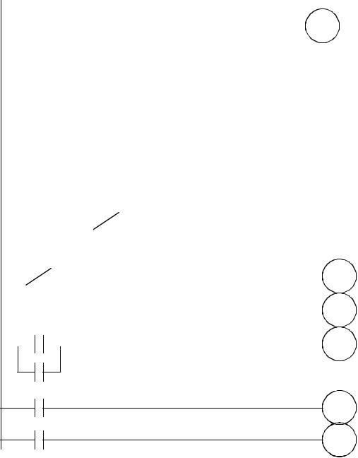
Figure 9.25 A Conveyor Controller Example
9.7.5 Accept/Reject Sorting
Problem: For the conveyor in the last case we will add a sorting system. Gages have been attached that indicate good or bad. If the part is good, it continues on. If the part is bad, we do not want to delay for 2 seconds, but instead actuate a pneumatic cylinder.
plc timers - 9.25
Solution:
|
|
Go |
Stop |
Light |
|
|||||
|
|
|
|
|
|
|
|
|
||
|
|
|
|
|
|
|
|
|
|
|
|
|
|
|
|
|
|
|
|
|
|
|
Light |
|
|
|
|
|
|
|
||
|
|
|
|
|
|
|
|
|
|
|
|
|
|
|
|
|
|
|
|
|
|
|
|
Part Detect |
|
|
|
TON |
T4:0 |
|||
|
|
|
|
|
|
|
|
|
||
|
|
|
|
|
|
|
|
Time base: 0.01 |
||
|
|
|
|
|
|
|
|
|||
|
|
|
|
|
|
|
|
Preset 150 |
|
|
|
|
|
|
|
|
|||||
|
|
|
|
|
|
|||||
|
|
T4:0/DN |
Part Good |
TON |
T4:1 |
|||||
|
|
|
|
|
|
|
|
|
||
|
|
|
|
|
|
|
|
Time base: 1.0 |
||
|
|
|
|
|
|
|
|
|||
|
|
|
|
|
|
|
|
Preset 2 |
|
|
|
|
|
|
|
|
|||||
|
|
|
|
|
|
|||||
|
|
T4:0/DN |
Part Good |
TON |
T4:2 |
|||||
|
|
|
|
|
|
|
|
|
||
|
|
|
|
|
|
|
|
Time base: 0.01 |
||
|
|
|
|
|
|
|
|
|||
|
|
|
|
|
|
|
|
Preset 50 |
|
|
|
|
|
|
|
|
|
|
|||
|
|
T4:1/EN |
|
Light |
Motor |
|
||||
|
|
|
|
|
|
|
|
|
||
|
|
|
|
|
|
|
|
|
|
|
|
|
T4:2/EN |
|
|
|
Cylinder |
||||
|
|
|
|
|
|
|
|
|||
|
|
|
|
|
|
|
|
|
|
|
|
|
T4:1/DN |
|
|
|
T4:0 |
RES |
|||
|
|
|
|
|
|
|
|
|||
T4:2/DN
T4:1/DN
T4:1 RES
T4:2/DN
T4:2 RES
Figure 9.26 A Conveyor Sorting Example