

Название-Сеть в Играх 2006год_Язык-Eng
.pdf124 Networking and Online Games: Understanding and Engineering Multiplayer Internet Games
Access networks are concerned with the delivery of framed packets from the user’s network connected device to the network. Access networks are differentiated from each other by their physical and data link layers.
8.2.1 Physical Layer
A network’s physical layer specifies the transmission medium and how individual bits are encoded onto it. The media used in access networks are wireless, coaxial cable, twisted copper pairs and optic fibre. The physical layer may also be responsible for minimising or even correcting errors as well as controlling access by multiple users.
Physical media include wireless where communications are mapped onto Radio Frequency electromagnetic radiation. For example, WLANs use a range of frequencies denoted as the Industrial, Scientific and Medical (ISM) Bands of around 2.4 GHz or 5.8 GHz. Cellular networks use frequencies around 800 to 900 MHz or 1900 MHz, depending on the particular network.
Coaxial cable is another commonly used medium. This is most commonly used in cable modems where the access network is overlayed on cable television network infrastructure.
Another broadband access network overlaid on an existing network is ADSL, which uses the twisted pair last hop of the Public Switched Telephony Systems Network (PSTN). Using sophisticated coding and error correction techniques, high bit rates can be obtained over the existing twisted pair medium.
The other commonly used medium is fibre optic cable. With this technology, the medium comprises very thin lengths of glass or plastic down which high-speed lasers or light-emitting diodes send light as the signal. Fibre optic cable is often used in hybrid fibre-coax Cable TV networks.
The physical layer specifies how individual bits are mapped onto the physical medium. The process of mapping a bit or a series of bits onto a medium is referred to as modulation. Wireless systems may encode bits as variations in the amplitude, phase or frequency of a carrier wave. Similar modulation schemes are used for coaxial cable and other electrical wire media. Bits transmitted across a fibre optic cable are typically encoded as pulses of light. The best method of modulation depends on the characteristics of the media it will use and the purpose of the network.
The physical layer specifies how communication channels are mapped onto the physical medium. There needs to be some way of dividing the physical medium into multiple channels. The process of mapping multiple channels onto one physical medium is called multiplexing. Multiplexing can be done using frequency division, time division, code division or a combination of all three.
In frequency division multiplexing (FDM), communications are modulated onto a carrier wave of a specified frequency and transmitted. The receiver filters out all frequencies other than that of the specified carrier wave, then demodulates the carrier wave to recover the original signal.
Time division multiplexing (TDM) involves allocating the medium to each channel for short periods of time. These periods of time are commonly called timeslots. TDM can be synchronous, where each channel is allocated a fixed number of timeslots in a given period, or asynchronous, where each channel is allocated a variable number of timeslots in a given period.
Broadband Access Networks |
125 |
|
|
Code division multiplexing (CDM) uses complex coding to separate multiple channels. CDM is a spread-spectrum technique. In this approach, each user’s communication is spread across the available spectrum along with everyone else’s but is encoded in such a way as to enable separation of different communication channels. This approach to multiplexing is widely used in wireless communication since it tends to be more resistant to the random variations in signal strength that wireless transmission is commonly subjected to and it makes very efficient use of scarce wireless bandwidth.
8.2.2 Data Link Layer
The data link layer is concerned with transmitting blocks of bits, called frames, from the transmitter to the receiver. In cases where multiple users access a single physical channel, it will usually provide some mechanism for managing the resulting contention which may occur if multiple users attempt to access the medium at the same time. This mechanism is identified as belonging to a sublayer within the data link layer, called the Medium Access Control (MAC) layer. The data link layer may also be responsible for error detection and correction and perhaps include some mechanism for retransmission of corrupted or missing frames.
Most broadband access networks, with the exception of ADSL use a shared medium and hence have an MAC sublayer. The most commonly used techniques for sharing access are contention-based schemes, where devices wishing to access the medium wait for it to be idle for a period of time before transmitting. If other users also transmit during this time, causing a collision, there must be some mechanism for resolving the conflict and retransmitting. Usually the approach is for all users to wait a random amount of time before retransmitting once the shared medium has become silent. This approach is used in some wired networks such as Ethernet and also some wireless networks such as WLAN. Another approach is a master-slave polling system where one device or node controls access to the medium. It specifies which device may transmit. This approach is also used in some wireless networks, notably Bluetooth and less commonly, WLANs.
The data link layer may also include some form of error correction or error detection, but this too is strongly dependent on the physical medium. In very reliable, high capacity media such as fibre optics, it may be unnecessary to provide any error correction. Where the medium is inherently unreliable, such as wireless, some form of error correction or detection is essential.
The physical and data link layers characterise the Access Network. They specify the medium to be used, how information is encoded, how users are multiplexed onto the medium and if any error control or detection is to be used. We now look at the most significant broadband access networks.
8.3 Cable Networks
Cable television networks are commonly used as an access network where there is a substantial cable television infrastructure. Using cable television networks as an access network allows owners of cable television networks to leverage their investment by providing network access to business and residential customers [ARM2000].
Cable television networks are usually implemented as an inverted tree, with the root of the tree referred to as the head-end where programming is injected into the network. The head-end supplies programming to the branches of the tree, which correspond to delivery

126 Networking and Online Games: Understanding and Engineering Multiplayer Internet Games
to particular regions of coverage and localities within those regions, and finally to the leaves of the tree representing the residential receivers of the television signal.
Cable television is built on the existing analogue TV distribution mechanism, and is thus intrinsically an analog medium at the consumer’s end. Each television channel occupies approximately 6 MHz. If a coaxial cable network is used from the head-end to the customer premises, then the signal that is distributed occupies Radio Frequencies (RF) in the range of 50 to 450 MHz in the downstream direction. For hybrid fibre-coaxial cable systems that use fibre optic cable in all but the last hop, the frequency range available is much higher, typically from 50 to 750 MHz. In the upstream direction, a much smaller 5 to 42 MHz may be available.
To use this analog medium as an Access Network for transporting digital communication, the digital signal must be modulated onto the analog carrier. An RF signal of 6 MHz can support bit rates in the megabit per second range, but to achieve this, there are a number of obstacles to overcome.
The first difficulty is that cable television is primarily a downstream broadcast medium. Upstream capacity is often limited or nonexistent. The second is that RF transmission is often subject to electrical noise that can severely limit modulation efficiency, particularly in the upstream direction. Finally, even with 750 MHz available, there is not enough capacity to allow a full channel to every user. The capacity has to be shared between multiple users through an MAC sublayer.
Dealing with the situation where there is no reverse channel is the most difficult. In this case, a hybrid solution where downstream communication is provided by the cable network and upstream communication is provided by the telephone network (using a suitable modulation system) is the most common solution, particularly where the network is solely coaxial cable based. Where the network is the more modern hybrid fibre-coaxial network, a reverse channel in the 5 to 42 MHz range, operating at a much lower rate than the downstream network, is a typical solution.
In order to control individual usage, some ISPs impose rate caps on the downstream bit rate. This has been shown to have quite serious consequences for latency when the link is overloaded with data traffic [NGUY2004a]. Even modest rate caps, in conjunction with excess data traffic, can cause latency increases of 100 ms or more. Certainly, this is something that should be of concern to game players and those deploying networked games requiring low latencies.
Standardisation of access networks using cable modems has been dominated by the industry-sponsored Data over Cable Service Interface Specification (DOCSIS). DOCSIS supports the delivery of Ethernet frames between the cable modem and the head-end. It implements a medium access control mechanism allowing shared access by multiple users.
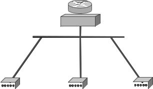
Figure 8.2 shows the main components in a simplified Data over Cable TV network. At the root of the tree that makes up the network is the head-end which provides connectivity to the Internet via a router or bridge. Each user connects to the branch which ultimately connects to the head-end.
Cable networks are an important and effective broadband access network. However, since they are based on a shared medium and rate caps, they can be subject to arbitrary variations in bandwidth and consequent random variations in delay.
Broadband Access Networks |
127 |
|
|
IP router or bridge
Head-end
|
|
|
|
|
|
|
|
|
Cable modem |
Cable modem |
Cable modem |
||||||
Figure 8.2 Data over a cable TV network
8.4 ADSL Networks
In the same way that cable modems leverage cable television networks to provide broadband access, so Digital Subscriber Line (DSL) technologies leverage existing telephone networks to provide broadband access. The most important of these technologies is Asymmetric Digital Subscriber Link (ADSL). ADSL is a member of a family of subscriber link technologies referred to as xDSL. It includes High-speed Digital Subscriber Line (HDSL), Very high-speed Digital Subscriber Line (VDSL) and others. The most commonly deployed is ADSL [ARM2000].
ADSL uses the existing PSTN twisted pair copper loop otherwise used for standard telephony. It operates in parallel with the existing telephone service but entirely independently of it. Broadband communications are transmitted over the copper loop at different frequencies to that used by standard telephony. With appropriate equipment it can be run in parallel but without affecting the existing telephony service.
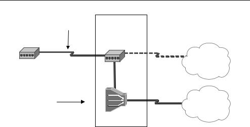
Figure 8.3 shows the main components of the ADSL architecture. At each end of the analog loop is an ADSL Transmission Unit (TU). It modulates the digital bitstream onto the local analog loop using frequencies above those used by telephony. At the local PSTN exchange the bitstream is demodulated by another ADSL TU and passed onto the parallel data network via a Digital Subscriber Line Access Module (DSLAM) which provides connectivity to the Internet. Unlike other networks, ADSL is not an end-to- end networking technology. It merely provides the last hop to a customer site. At the exchange, communications over the ADSL link are separated from any other telephony communications and transferred through an entirely independent network.
ADSL is, as its name suggests, highly asymmetric in its upstream and downstream data rates. Downstream rates are typically from 1.5 Mbps to 9 Mbps, whereas upstream rates are typically 16 kbps to 640 kbps. The actual speeds obtained depend on the distance and quality of the copper loop between the customer’s residence and the local exchange.
The international telecommunications union (ITU) specification for ADSL (G.992.1) specifies two quite distinct paths with quite different latency characteristics in each direction [ITU1999a]. The fast path minimises latency but at the possible expense of
128 Networking and Online Games: Understanding and Engineering Multiplayer Internet Games
Analogue loop |
Local PSTN |
|
exchange |
||
|
||
ADSL TU |
ADSL TU |
|
|
PSTN
Parallel |
|
network |
Internet |
|
DSLAM |
Figure 8.3 Asymmetric digital subscriber line
reliability while the interleave path provides mechanisms for improving reliability but at the cost of additional delay. An interleave path only version of ADSL is defined in G.992.2 [ITU1999b]. In cases where both paths are defined, capacity can be distributed between the two paths. This distribution can occur during use, but causes latency of up to 20 ms.
ADSL is designed to adapt to changing characteristics of the copper loop. Although it occurs infrequently, when link speeds are adapted up or down, quite long delays of up to 3 seconds can be experienced during the adaptation process with obvious consequences for game players.
ADSL is mostly used in association with another access network technology. ADSL provides connectivity between the residence and the exchange. Another home network technology is used to connect individual users to the ADSL network. A typical installation will use ADSL to provide connectivity to the wide area and WLAN to provide multiuser access within the residence. Consequently, apart from variations in latency caused by capacity distribution between the interleave and fast paths, it can also be subject to random variations in capacity caused by sharing the link with other users within the residence.
ADSL is an important broadband technology. It provides high-speed access over existing telephony links. However, like most broadband access networks, it can be subject to random fluctuations in bit rates and latency.
8.5 Wireless LANs
Perhaps the most interesting recent developments in access networks have been in wirelessbased access, particularly that class of wireless technologies known as WLAN or WiFi.
WLANs provide great flexibility and convenience for those providing and using an access network. Access network coverage can be provided quickly and easily. Many user devices such as laptops and Personal Digital Assistants now have WLAN networking cards built into them.
Broadband Access Networks |
129 |
|
|
WLAN coverage is usually quite small. Depending on the power of the transmitter and receiver, reliable coverage is usually restricted to a radius of twenty metres although with line of sight and sophisticated antennae much greater distances can be covered. However, its purpose is primarily to provide coverage over a reasonably small area. Consequently, WLAN is usually deployed in association with some other access network technology, such as ADSL or cable modem.
8.5.1 IEEE 802.11 Wireless LAN Standards
WLANs use the family of protocols defined by the Institute of Electrical and Electronic Engineers (IEEE) who have also been instrumental in standardising other popular protocols such as Ethernet. WLAN standards are collectively known as the 802.11 standards [IEEE2004], [GAST2002].
802.11 is a family of standards. All 802.11 networks use a common MAC layer but vary in the physical layer details. There have been a number of different physical layer standards released since the original 802.11 standard in 1997, but the most commonly used are the 802.11b and the 802.11g standards operating in the 2.4 GHz ISM band. The ISM band is an area of minimally regulated bandwidth in which anyone may operate radio equipment subject to a minimal set of restraints, primarily on power levels. Consequently, although 802.11 equipment does not need special licensing to install and run, it is potentially subject to interference from other equipment. These include short range Bluetooth communications devices, some cordless telephones and microwave ovens. In designing the IEEE 802.11 protocol, care was taken to make it resistant to interference from other sources. However, this resistance is implemented as a graceful degradation from high bit rates where there is no interference to lower bit rates as interference increases. Consequently, WLANs can be subject to seemingly random changes in bit and error rates when other equipment that broadcasts in the ISM band is used nearby.
802.11b and 802.11g divide the ISM band into 14 overlapping channels with centre frequencies 5 MHz apart. Channels are numbered consecutively from 1 to 14. Within the same coverage area, users may access channels separated by 25 MHz. So in one coverage area users might access channels 1, 6 and 11, while in a neighbouring area they might use 2, 7 and 12. Separation of these channels is important. If user equipment or access points do not maintain this separation, then the result can be additional interference and consequent increases in errors and lower bit rates.
8.5.2 Wireless LAN Architectures
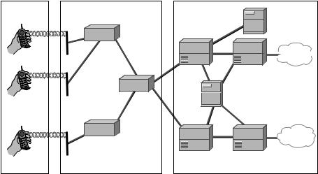
The 802.11 standard specifies two kinds of network architectures: infrastructure and ad hoc networks. Infrastructure networks make use of an Access Point (AP) to control communication between users and to provide a communication path to the Internet. In ad hoc networks (or peer-to-peer), users’ equipment communicates directly without mediation by an AP. For 802.11 to be used as an access network, communication must be via an AP. However, the AP itself needs to be connected to the Internet. This is often via another broadband access network such as an ADSL or a Cable Modem network. Figure 8.4 shows an infrastructure network connecting three APs, each with two wireless nodes. In this kind of network, communication between wireless nodes is usually via the AP rather than directly between them.

130 Networking and Online Games: Understanding and Engineering Multiplayer Internet Games
The Internet
Figure 8.4 Infrastructure wireless LAN
Access to any of the channels supported by the AP is shared. That is, the same channel can support multiple users. However, since the channel has a maximum bit rate, (11 Mbps in 802.11b and 55 Mbps in 802.11g) increasing the number of users decreases the bit rate available to each user.
802.11 networks provide some support for mobility. Users can move from one AP network to another where the APs belong to the same Extended Service Set. However, handover between access points can be quite slow.
WLAN has also experienced security and privacy problems [POTT2002]. Whether this is an important issue for game players is something that individual players and game system operators need to decide for themselves. However, in cases where games intersect with the real economy through professional games with prize money or where game artefacts can be sold for real money, security is certainly important. In general, security on 802.11 networks is weak. The original intention was to have security comparable to wired networks; the so-called Wired Equivalence Privacy (WEP). Unfortunately, because it is so easy to eavesdrop on wireless communication, a level of security appropriate for wired communication has proven to be unsatisfactory for wireless communication. Fortunately, the IEEE and the WiFi alliance have recognised this weakness and have released other solutions such as WPA and 802.1X, which provide a more satisfactory level of security.
Shared communication in a wireless environment suffers a problem not experienced in wired communications; that of the hidden terminal. Shared media are usually managed through some kind of contention scheme. A station waits until the shared medium is idle and then, after a random amount of time, transmits onto the shared medium. If another station is also waiting to transmit, there will be a collision. This is usually managed through some random wait before transmitting again. Such a scheme is the basis of Ethernet. However, adapting this scheme to a wireless network is difficult. In a wired medium, a collision is easy to detect. The station monitors the signal it transmits and compares it with what actually appears on the medium. If they differ, then there has been a collision. Unfortunately, detecting collisions where a wireless medium is involved is much more complicated. Two stations may be within range of an AP but not within range
Broadband Access Networks |
131 |
|
|
of each other. They may both transmit at the same time causing a collision at the AP, but which they will be unaware of. The terminals are ‘hidden’ from each other.
To manage the hidden terminal problem, WLAN uses Carrier Sense Multiple Access/ Collision Avoidance (CSMA/CA). CSMA/CA works by requiring an acknowledgement from the destination of every frame transmitted. While this is effective in detecting collisions, it has the effect of reducing the available bit rate substantially. Simulations have suggested that for 802.11b, if communication is primarily TCP-based, 5.9 Mbps is available to be shared and if communication is primarily UDP, 7.1 Mbps is available, substantially less than the raw 802.11b bit rate of 11 Mbps.
Most 802.11 networks use the Distributed Coordination Function (DCF), with CSMA/CA to manage contention for the shared channel. In the DCF, a station that wishes to transmit must detect that the medium has been idle for a specified period of time, which is referred to as the Distributed Control Function Interframe Space (DIFS). If another station also tries to transmit at the same time, there will be a collision which will be detected through the CSMA/CA mechanism. The station now waits an Extended Interframe Space (EIFS). The EIFS is a randomly selected length of time whose maximum value increases as the number of failed attempts to transmit increases.
Although DCF is simple, it causes random variations in delay and bit rate. With DCF, once a station gains access to the medium it may keep the medium for as long as it chooses. The number of users sharing the medium and interference from other devices operating in the ISM band will further affect the bit rate available to each user while the CSMA/CA contention mechanisms reduces it even further. Consequently, WLAN access networks can be subject to random variations in delay and bandwidth depending on the number of users and other devices operating in the ISM band.
8.5.3 Recent Developments in WLAN Quality of Service
Because WLAN channels are shared, Quality of Service can be difficult to guarantee. The available capacity is not only shared by all users but also users whose traffic has different round trip times (as the result of one user accessing a local server and another a more remote server) it can experience quite different values in latency [NGUY2004b]. For example, where an 802.11b WLAN is shared between clients accessing data from a local server while others accessing it from a remote server, latencies of up to 100 ms have been observed. For game players, latencies of this order are a serious problem.
To provide some guarantees of Quality of Service (QoS) for delay-sensitive applications, the 802.11e Working group has been investigating enhancements to the 802.11 MAC layer. The work of 802.11e builds upon the little used Point Coordination Function (PCF) defined, but rarely implemented, in the 802.11 MAC layer. The purpose of the PCF is to allow access to the medium in a fair manner controlled by the AP. When PCF is used, time on the medium is divided into a Contention Free Period (CFP) and a Contention Period (CP). During the Contention Period, access is controlled by the DCF. During the Contention Free Period, access is controlled by the PCF. Each station is polled by the AP for any data to be transmitted. If no response is received within a Point Control Function Interframe Spacing (PIFS) then the next station is polled. The PIFS is shorter than the DIFS, ensuring that PCF has priority over DCF. This mechanism provides guaranteed bandwidth for delay-sensitive applications such as voice and games.

132 Networking and Online Games: Understanding and Engineering Multiplayer Internet Games
Working group 802.11e has developed both the DCF and PCF schemes to introduce a more effective Quality of Service mechanism. The Enhanced Distributed Coordination Function (EDCF) distinguishes between high priority traffic and low priority traffic. High priority traffic waits a shorter period of time than low priority traffic before transmitting. This scheme is simple to implement but provides only relative guarantees of QoS.
The second mechanism developed by 802.11e is the Hybrid Coordination Function (HCF). This is based on the PCF but allows the definition of traffic classes. Different traffic classes can be defined to provide different QoS based on characteristics such as bandwidth and maximum jitter. These are controlled by modifying the frequency with which a station generating a particular traffic class is polled and the maximum number of frames that a station may transmit in response to a poll.
8.6 Cellular Networks
Cellular voice networks such as Global System for Mobile (GSM) and cdmaOne have been commonplace now for over twenty years, but cellular networks able to support packet data at broadband rates are only just becoming widely available. Generally, when compared with other wireless technologies, broadband cellular networks provide much greater coverage, lower latency and seamless handover but at lower bit rates and often, at very high usage costs. Important developments in broadband cellular access networks are Enhanced Data Rates for Global System for Mobile Equipment (EDGE), General Packet Radio System (GPRS), CDMA2000 and Universal Mobile Telecommunications System (UMTS). EDGE and GPRS are sometimes referred to as 2.5G networks, while CDMA2000 and UMTS are sometimes referred to as 3G networks. These technologies can provide broadband wireless access across a much wider area than is possible with other wireless technologies. However, they require the deployment of a great deal of infrastructure, the purchase of bandwidth licenses at often staggeringly high prices, and sophisticated end-user equipment. Consequently, usage costs tend to be high.
Because of their expense and strict bandwidth licensing requirements, cellular networks are usually deployed by large telecommunications companies or specialised wireless communications companies. Comparatively low cost, privately deployed cellular networks are, at least for now, not possible.
8.6.1 GPRS and EDGE
GPRS is derived from the GSM telephony system. Its purpose is to make efficient use of the GSM network for data purposes with a minimum deployment of additional hardware. GPRS is now commonly deployed wherever GSM telephony systems are deployed. However, while GPRS is an excellent packet data network, its delay performance is very poor. It is intended for the efficient communication of nonreal-time communications such as emails and web browsing [PAHL2002]. The GPRS standard defines four delay classes. Class 1 specifies a mean delay of less than two seconds, class 2 a delay of less than 15 seconds, class 3 a delay of less than 75 seconds and class 4 does not specify any delay. Clearly, delays of this magnitude make it unsatisfactory for real-time games. Nevertheless it may be of use to players of nonreal-time games.
EDGE is not so much an alternative network as an improvement to the modulation scheme used in the GSM air interface. By adapting the bit rate to the quality of the link,
Broadband Access Networks |
133 |
|
|
much higher bit rates are possible than with standard GSM. However, once again its purpose is primarily the transfer of nonreal-time data with no guarantees as to the delay.
8.6.2 3G Networks
3G technologies such as CDMA2000 and the UMTS are probably of much more interest to game players. CDMA2000 has been standardised in the United States by the Telecommunications Industry Authority and UMTS (sometimes W-CDMA) has been standardised by the European Telecommunications Standards Institute (ETSI). CDMA2000 has largely been derived from the earlier IS95 standard (often referred to as cdmaOne) while UMTS is derived from the GSM standard [DAHL1998].
Both UMTS and CDMA2000 support similar services including high-speed Internet access and QoS guarantees. Both can support asymmetric data rates.
Broadband cellular networks are being standardised as part of the International Mobile Telecommunications 2000 Programme (IMT-2000) under the auspices of the ITU. Although terminology differs between standards, broadband cellular networks generally share a common architecture. The simplified architecture for UMTS is shown in Figure 8.5 [UMTS2005]. There are three high-level components in this architecture: the User Equipment (UE), the Universal Terrestrial Radio Access Network (UTRAN) and the Core Network (CN). This high-level architecture is typical of cellular networks [SCHI2003].
In UMTS, the UE is a multimedia capable handset. Apart from voice calls, it supports multimedia calls and packet data. The UE is connected to the UTRAN via the radio interface. The UTRAN is concerned with maintaining connectivity to the UE and with seamless handover both within and between Radio Network Subsystems (RNSs). The CN is responsible for more complex forms of handover and for providing connectivity to other networks, including the Internet.
Each of these systems has an internal structure. The UE is made up of the actual handset itself (the mobile equipment or ME) and a smart card containing user identity
User |
UTRAN |
|
equipment |
||
|
Node B |
RNC |
Node B |
Core network
VLR
MSC |
HLR |
SGSN |
GMSC 

 PSTN
PSTN 
GGSN |
Internet |
|
Figure 8.5 UMTS cellular broadband network