


Here is the NAT table of Router 1; notice that PAT creates an extended entry and all fields of the output are populated:
Router−1#show ip nat translations
...
Pro |
Inside global |
Inside local |
... |
TCP |
192.168.10.254:1036 |
10.10.10.3:1036 ... |
|
TCP |
192.168.10.254:1037 |
10.10.10.162:1037 ... |
|
TCP |
192.168.10.254:1056 |
10.10.10.15:1056 ... |
|
... Outside local |
Outside global |
... 20.20.20.184:23 |
|
20.20.20.184:23 |
|
... 20.20.20.200:23 20.20.20.20:23 |
|
... 20.20.20.21:23 |
20.20.20.21:23 |
Note Because of the format limitations of this book, lines of code have been broken with ellipses points.
Configuring Committed Access Rate (CAR)
The process for configuring CAR to rate−limit traffic is fairly straightforward. To configure a CAR policy for IP traffic, use the following steps beginning in global configuration mode:
1. Enter interface configuration using the following command:
interface interface−type interface−number
2. Use this command to specify a CAR policy:
rate−limit {input|output} [access−group [rate−limit] − access−list−number] <bps><burst−normal><burst−max> − conform−action action exceed−action action
3. Use this command to define a CAR policy based on the contents of the access list:
access−list access−list−number {deny|permit} [protocol] − [source] [source−wildcard] [destination] [destination− wildcard] −
[precedence precedence][tos tos] [log]
The preceding commands are all that are needed to define a policy to rate−limit traffic. Cisco Express Forwarding (CEF) must also be enabled for CAR to operate. Figure 3.9 shows a network in which Router A and Router B are neighbors. Router A is the customer edge perimeter router for Company A and provides Internet access for the company. Router B is the provider edge router for ISP B, which provides Internet access to Company A. Company A would like to configure Router A such that it will rate−limit DoS packets during an attack. Listing 3.18 details the configuration commands needed to enable CAR on each router.
Listing 3.18: Router A configured for rate−limiting.
#config t #ip cef
#access−list 110 permit icmp any any echo #access−list 110 permit icmp any any echo−reply
116
#interface serial3/0
#rate−limit input access−group 110 32000 8000 8000 − conform−action transmit exceed−action drop
Figure 3.9: Rate−limiting Denial of Service.
The steps shown earlier include the basic configuration commands needed to enable CAR for rate−limiting traffic. The configuration shown in Listing 3.18, enables CEF on a global basis for the router. CEF must be enabled for CAR to provide rate−limiting services. Access list 110 matches ICMP traffic. The access list is applied to CAR under the serial interface for inbound traffic. Notice that the rate− limit command defines the extended burst limit as being the same as the normal limit, which effectively disables the extended burst capability. Use the show running−config command to see the output of the configuration, which is shown in Listing 3.19.
Listing 3.19: Rate limit configuration of Router A.
Router−A#sh ru
Building configuration...
!
ip cef
!
interface Serial3/0
ip address 192.168.10.9 255.255.255.252
rate−limit input access−group 110 32000 8000 8000 − conform−action transmit exceed−action drop
!
access−list 110 permit icmp any any echo access−list 110 permit icmp any any echo−reply
!
When you issue the show running−config command, you can review the configuration changes that were made to the local device; however, a few more commands are needed in order to verify the operation of CAR. After you verify that the configuration changes are correct, you should issue the show interface rate−limit command. The output of this command verifies the configuration of CAR and allows you to monitor CAR statistics. The output of the command is shown in Listing 3.20.
Listing 3.20: Verifying the operation of CAR.
Router−A# sh int ser3/0 rate−limit
Serial3/0 Internet Connection (Network Engineering) Input
matches: access−group 110
params: 32000 bps, 8000 limit, 8000 extended limit conformed 445884 packets, 128442746 bytes; action: transmit exceeded 22272 packets, 15068096 bytes; action: drop
last packet: 3176ms ago, current burst: 0 bytes
117

last cleared 1w5d ago, conformed 0 bps, exceeded 0 bps Router−A#
The output of the show interface rate−limit command first lists the direction that rate−limiting is applied, inbound or outbound. The next line defines the access list for traffic that CAR is using to apply its policy. And the next line defines the parameters that CAR applies to traffic matching the defined access list. The output then shows the number of packets that CAR defined as conforming to or exceeding the defined limits.
In the configuration in Listing 3.20, Company A defined its rate−limiting policy for ICMP traffic. The configuration effectively polices the traffic; however, the traffic is policed after traveling across Company A's upstream connection from ISP B. Enterprises traditionally connect to their ISP via smaller links, and their ISP connects to neighboring peers on the Internet via much larger links. In situations in which the attack takes on a distributed form that uses hundreds or thousands of zombie machines running preconfigured bots, the traffic that is generated can consume the enterprise's link to its service provider. The example in Figure 3.9 depicted Company A connected to ISP B via one single T1 connection running at 1.544 megabits. With the configuration in Listing 3.18, ICMP travels across the T1 only to be dropped at Router A. Although Router A performs the rate−limiting function, the configuration in Listing 3.20 does nothing to deny traffic from traveling across the link.
In these instances, ISP B should configure Router B to deny ICMP traffic from traveling across the T1, thus allowing legitimate traffic while denying nonlegitimate traffic. The configuration for Router B is shown in Listing 3.21; the configuration for Router B is similar to the configuration for Router A except that the rate−limiting feature is applied in an outbound direction.
Listing 3.21: Router B configuration.
#config t #ip cef
#access−list 110 permit icmp any any echo #access−list 110 permit icmp any any echo−reply #interface serial2/1
#rate−limit output access−group 110 32000 8000 8000 − conform−action transmit exceed−action drop
In both configurations, Listing 3.20 and Listing 3.21, each router has been configured to rate−limit ICMP traffic, or what is commonly referred to as the Ping of Death and Smurf attacks.
Note Smurf attacks use a combination of IP spoofing and ICMP traffic to saturate a target network by sending a spoofed Ping packet to the broadcast address of a large network. The packet contains the source address of the actual target machine.
There are other forms of DoS attacks. Another common attack is the SYN attack, in which an attacker exploits the use of buffer space used during the TCP session initialization handshake. CAR can be used to rate−limit this type of traffic. Refer again to Figure 3.9; Router A should be configured to rate−limit all ICMP traffic and traffic that contains characteristics of a SYN attack. This configuration defines multiple rate−limiting policies and is detailed in Listing 3.22.
Listing 3.22: Multiple rate−limiting policies configuration.
#config t #ip cef
118

#access−list 110 permit icmp any any echo #access−list 110 permit icmp any any echo−reply #access−list 111 deny tcp any any established #access−list 111 permit tcp any any
#interface serial3/0
#rate−limit input access−group 110 32000 8000 8000 − conform−action transmit exceed−action drop
!
#rate−limit input access−group 111 64000 4000 4000 − conform−action transmit exceed−action drop
In this example, two access lists, as well as two rate−limiting policies, have been defined. Access list 110 rate−limits ICMP traffic to defend against Ping attacks, and access list 111 defends against SYN floods. When you issue the following command, established sessions won't be considered in the rate−limiting policy:
access−list 111 deny tcp any any established
This command rate−limits all initial SYN packets the router receives; the remaining packets in the flow will conform to the deny statement in access list 111 and not be rate−limited:
access−list 111 permit tcp any any
Configuring Logging
The process for configuring a router to log events is fairly straightforward and simple, yet it's one of the most important security configuration changes that security administrators will make on their routers. To enable logging, follow these steps:
1.Use the logging on global configuration command to enable logging of messages. This command is enabled by default and will be needed only if message logging has been disabled.
2.Use the following command to configure all logging messages to contain the same IP address:
logging source−interface <interface type interface number>
By default the logging message contains the IP address of the interface it uses to leave the router.
3.Use this command to define a logging server that should receive the logging messages (more than one host may be defined):
logging <buffered|monitor|console|ip address>
4.Use the logging trap <level> command to define the level of detail for logged messages. Table 3.1 earlier in this chapter lists event error messages and their corresponding severity levels.
5.Use the following command to enable time stamping of log messages:
119
service timestamps log <datetime|uptime> [msec] [localtime] [show timezone]
The logging buffered command copies logging messages to an internal buffer within the router. This buffer is circular in nature, meaning newer messages overwrite older messages when the buffer becomes full. The logging ip address command identifies a server to receive logging messages. The logging monitor command logs messages to the nonconsole terminal. The logging console command copies logging messages to the console port of the router.
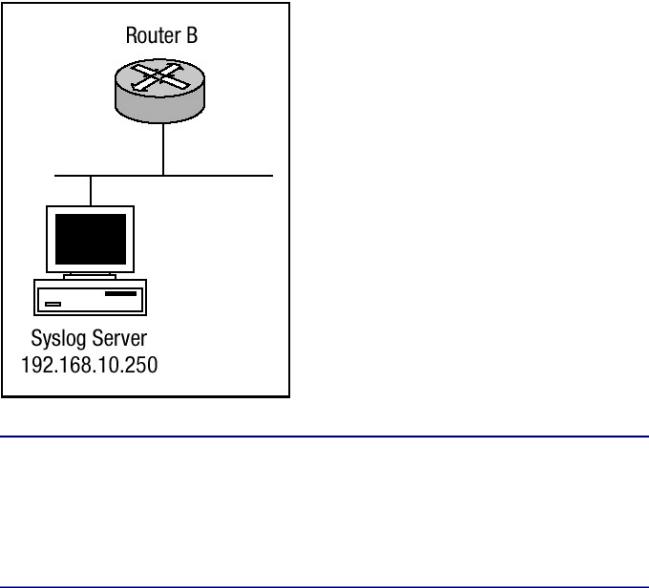
Router B in Figure 3.10 is configured to send warning level logging messages to the syslog server at IP address 192.168.10.250. Router B is configured with a loopback interface that has an IP address of 192.168.11.1, and this interface is to be the source of all logging messages that Router B sends. Listing 3.23 details the configuration commands needed to enable Router B for message logging to host 192.168.10.250.
Figure 3.10: A network design with logging defined.
Listing 3.23: Router B's logging configuration.
#config t
#service timestamps log uptime #service timestamps log datetime msec #no logging console
#logging 192.168.11.1
#logging source−interface loopback1 #logging trap 4
#end
#
In Listing 3.23, Router B has been configured to log warning level messages to the system logging server with an IP address of 192.168.11.1. To verify that logging has been properly configured, issue the show logging command. Listing 3.24 displays the output.
120

Listing 3.24: Show logging output.
Router−B#show logging
Syslog logging: enabled (0 messages dropped, 0 flushes, 0 overruns)
Console logging: disabled
Monitor logging: level debugging, 0 messages logged Buffer logging: level debugging, 146 messages logged Trap logging: level warning, 151 message lines logged
Logging to 192.168.11.1, 151 message lines loggedxs Log Buffer (8192 bytes):
:%SONET−4−ALARM: POS0/1/0: B3 BER exceeds threshold
:%SONET−4−ALARM: POS0/1/0: B3 BER below threshold
:%WCCP−5−CACHEFOUND: Web Cache 192.168.31.32 acquired
:%WCCP−5−CACHEFOUND: Web Cache 192.168.31.31 acquired
:%STANDBY−6−STATECHANGE: Standby: 1: Vlan1 state Standby
:%STANDBY−6−STATECHANGE: Standby: 1: Vlan1 state Active
:%STANDBY−6−STATECHANGE: Standby: 1: Vlan1 state Speak
The output in Listing 3.24 shows that console logging has been disabled. Monitor and buffer logging are logged at the default debugging level. Notice that the trap logging has been changed from the default informational logging level to the warning level and the server the trap messages are sent to is displayed as well. The show logging command also displays the number of messages logged by each method.
Another command that can be used to view logging information is the show logging history command. The output of the show logging history command displays information in the system logging history table, such as the table size, the status of messages, and the text of the messages stored in the table. If the logging of message traps to a Simple Network Management Protocol (SNMP) management station, be sure network management station traps has been enabled with the snmp−server enable trap command.
The level of messages sent and stored in a history table on the router can be changed. The number of messages that get stored in the history table can be changed as well. Messages are stored in the history table because SNMP traps are not guaranteed to reach their destination. By default, one message of the level warning is stored in the history table even if log traps are not enabled. The output of the show logging history command is shown in Listing 3.25.
Listing 3.25: Show logging history output.
Router−B#sh logging history
Syslog History Table:1 maximum table entries, saving level warnings or higher
73 messages ignored, 0 dropped, 0 recursion drops
72 table entries flushed
SNMP notifications not enabled
entry number 73 : SYS−4−SNMP_WRITENET
SNMP WriteNet request. Writing current config to 192.168.11.1 timestamp: 313923920
Router−B#
As mentioned earlier, the logging history level can be changed; notice in Listing 3.25 that the logging history table lists 1 maximum table entry. The table history size can be changed as well. You can change the history level as well as the size of the history table by using the following commands:
121

1.Use the logging history <level> command, where the level equals the values detailed in Table 3.1, to change the default level of log messages stored in the history file and sent to the SNMP server.
2.Use the logging history size <size> command, where the size is a number between 0 and 500, to change the number of log messages that can be stored in the history table.
The following commands add the logging history and logging history size commands to the configuration of Router B. The arguments of these commands should be reflected in the show logging history command:
#config t #logging history 3
#logging history size 400 #end
#
The configuration changes that were made can be seen in the output of the show logging history command. Listing 3.26 reflects the changes that were made.
Listing 3.26: Show logging history.
Router−B#sh logging history
Syslog History Table:400 maximum table entries, saving level errors or higher
73 messages ignored, 0 dropped, 0 recursion drops
72 table entries flushed
SNMP notifications not enabled entry number 74 : SYS−5−CONFIG_I
SNMP WriteNet request. Writing current config to 192.168.11.1 timestamp: 176910958
Related solution: |
Found on page: |
Configuring SNMP Security |
26 |
122