

Микропроц техника / 4 курс_МТ_МСУД / 8051easy_manual
.pdfm i k r o E l e k t r o n i k a d e v e l o p m e n t s y s t e m s |
|
8051easy |
|
|
|
|
|
|
|
|
|
|
|
|
|
|
development system |
|
|
8051easy
Manual
October 2002.
PIC, AVR, MC68HC11, i8051, PSoC development systems www.mikroelektronika.co.yu
m i k r o E l e k t r o n i k a d e v e l o p m e n t s y s t e m s |
|
8051easy |
|
|
|
|
|
|
|
|
|
|
|
|
|
|
development system |
|
|
CONTENTS
Installation of the System |
strana 2 |
Programming the Microcontrollers in the |
|
Development System |
strana 3 |
Description of the Development System |
strana 7 |
Power Supply |
strana 7 |
LED Diodes |
strana 7 |
Buttons |
strana 8 |
LCD Display |
strana 9 |
Seven-segment Display |
strana 11 |
A/D Conversion |
strana 12 |
RS232 Communication |
strana 13 |
Digital Termometer - DS1820 |
strana 14 |
Pull-up,Pull-down Resistors on Ports |
strana 15 |
Direct Access to Ports |
strana 16 |
PIC, AVR, MC68HC11, i8051, PSoC development systems www.mikroelektronika.co.yu |
I |
m i k r o E l e k t r o n i k a d e v e l o p m e n t s y s t e m s |
|
8051easy |
|
|
|
|
|
|
|
|
|
|
|
|
|
|
development system |
|
|
INSTALLATION OF THE SYSTEM
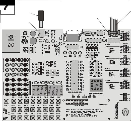
When you open the box of the development system, it should contain development system, CD, programmer and a serial cable (LCD, LTC1290, REF02, oscilator 4MHz and temperature sensor DS1820 are optional when ordering the package). Installing the system takes just 3 steps:
Step no.1 The first thing to do is taking the system out of box and connecting the programmer to IDC10 in the upper right corner of the development system. The other end of programmer should be directly connected to paralel port of the computer.
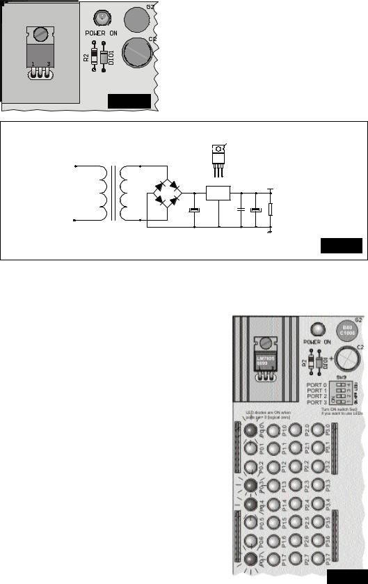
Step no.2 The next step is connecting to the power supply. Power supply can be both AC/DC accordingly. Supply voltage is 9 to 12 V (AC or DC). The picture below illustrates the first contact with the development system.
Step no.3 Installation of AVR ISP software. Run SETUP.EXE in folder
...\CD\ISP or directly by clicking the ISP link on the first page of presentation provided on the CD. After short and simple procedure (answer all the questions with yes) installation is complete.
Picture 2.
Power Supply
Napajanje
AC/DCAC/DC 99--12V12V
Power Supply
Konektor za
Connector
napajanje
Connector for Rs232 Konektor za Rs232 komunikaciju Communication of microcontroller mikrokontrolera i racunara.
and a computer (it is not used for (Ne koristi se za programiranje programming the microcontroller) mikrokontrolera)
FlatFletcablekablconnectingkoji povezujethe systemsistemto thesa AVRAVR DongleDongle
Connector for programming
programmerprogramatorom
Konektor za programiranje
using AVR Dongle pro- preko AVR Dongle
grammer programatora
B80
C1000
+ 
LM7805
0099
|
|
4 |
|
|
3 |
|
ON |
1 2 |
LED diodes are ON when |
Turn ON switch Sw3 |
|
ports pin= 0 [logical zero] |
if you want to use LEDs |
|
+ |
+
|
MAX232 |
|
|
+ |
+ |
+ |
+ |
Turn on switch Sw2 if you want to use displays
|
4 |
|
3 |
ON |
1 2 |
4MHz
PI
ER H
SP A I
N
LCD contrast
PIC, AVR, MC68HC11, i8051, PSoC development systems www.mikroelektronika.co.yu |
2 |

m i k r o E l e k t r o n i k a d e v e l o p m e n t s y s t e m s |
|
8051easy |
|
|
|
|
|
|
|
|
|
|
|
|
|
|
development system |
|
|
PROGRAMMING THE MICROCONTROLLERS IN THE DEVELOPMENT SYSTEM
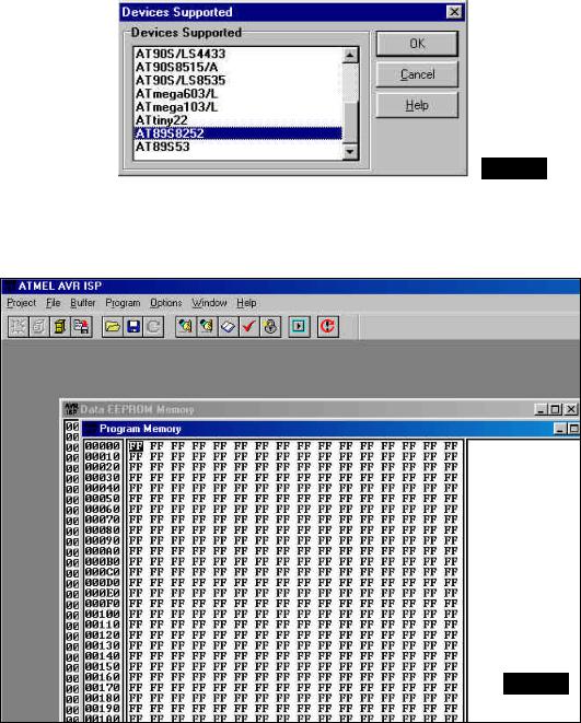
Step no.1. Start AVR ISP program and the following screen should appear.
Picture 3.
Step no.2. Click PROJECT -> NEW PROJECT as shown on a picture below.
Picture 4.
PIC, AVR, MC68HC11, i8051, PSoC development systems www.mikroelektronika.co.yu |
3 |
m i k r o E l e k t r o n i k a d e v e l o p m e n t s y s t e m s |
|
8051easy |
|
|
|
|
|
|
|
|
|
|
|
|
|
|
development system |
|
|
Step no.3. By double clicking the mouse select the appropriate controller (pic. 4.)
Picture 5.
By clicking on a certain microcontroller Program Manager window opens and it cannot be closed, but it can be hidden by clicking one of the windows behind it (i.e. Program Memory ), as shown on picture 6.
Picture 6.
PIC, AVR, MC68HC11, i8051, PSoC development systems www.mikroelektronika.co.yu |
4 |
m i k r o E l e k t r o n i k a d e v e l o p m e n t s y s t e m s |
|
8051easy |
|
|
|
|
|
|
|
|
|
|
|
|
|
|
development system |
|
|
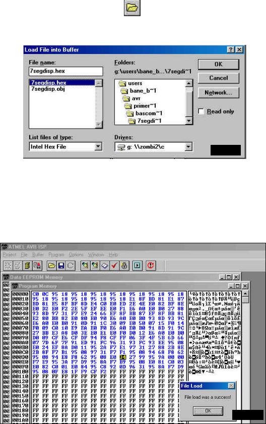
Step no.4. Clicking the icon
appropriate program. To make detection easier, Intel Hex File option should be selected - the upper left corner of Load File In Buffer window (picture 7.).
Picture 7.
After the wanted HEX or ROM file has appeared, click it and load it to buffer with OK, after which it will be transferred to microcontroller.
NOTE: HEX file can be created using any assembler, BASIC or C compiler.
Step no.5. After successful loading to computer buffer, following picture should appear. Clicking the OK in the File Load window ends loading the program.
Picture 8.
PIC, AVR, MC68HC11, i8051, PSoC development systems www.mikroelektronika.co.yu |
5 |
m i k r o E l e k t r o n i k a d e v e l o p m e n t s y s t e m s |
|
8051easy |
|
|
|
|
|
|
|
|
|
|
|
|
|
|
development system |
|
|
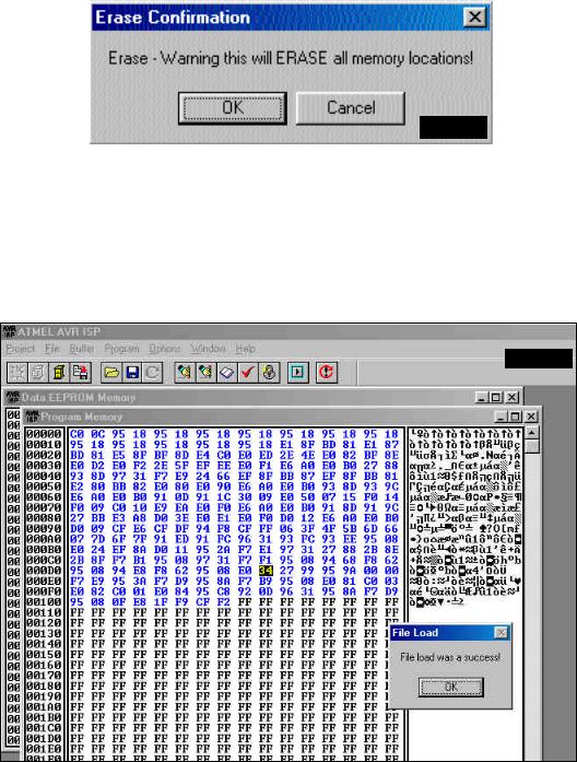
Step no.6. The next step is erasing the microcontroller memory. Click the icon  and confirm the action with OK.
Picture 9.
Step no.7. Clicking the icon  starts the programming, which lasts briefly. After successful programming, the window shown on the following picture will appear. Click the OK and formally end loading in the microcontroller memory.
Picture 10.
NOTE: You should not unplug the flat cable from the programming connector , because it helps a great deal when you are frequently programming!
PIC, AVR, MC68HC11, i8051, PSoC development systems www.mikroelektronika.co.yu |
6 |
m i k r o E l e k t r o n i k a d e v e l o p m e n t s y s t e m s |
|
8051easy |
|
|
|
|
|
|
|
|
|
|
|
|
|
|
development system |
|
|
DESCRIPTION OF THE DEVELOPMENT SYSTEM
POWER SUPPLY
B80
C1000
+ 
LM7805
0099
Picture 11.
For all the elements in the development system to work properly, it is required to have stabilized +5V. With AVR-easy system, it is achieved by using the power stabilizer LM7805. Because of the increased dissipation which occurs at higher current consumption, stabilizer is set upon the appropriate cooler.
Transformator
2
220-  LM
LM
TO 7805
|
|
~ |
B80C1000 |
|
1 2 3 |
|
|
|
|
|
|
|
|
|
|
|
|
- |
+ |
1 |
|
3 |
+5V |
220V~ |
9V~ |
LM7805 |
|
||||
|
|
|
|
|
|||
|
|
|
C1 |
|
2 |
C2 |
C3 |
|
|
|
~ |
|
|
|
R |
|
|
C1 = 22μF, C2 = 100nF, |
|
|
|
|
|
|
|
C3 = 10μF, R = 1K |
|
|
|
Picture 12. |
|
|
|
|
|
|
|
|
|
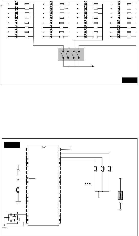
LED DIODES
The system has 32 diodes that are connected to the port 0, 1, 2, and 3 pins. These diodes are ordinarily used in the first phase of the work, but they can be also used for the later indications of the program flow. Each set of the diodes can be turned on and off using the SW3 switch. The way to connect the LED diodes with a microcontroller is shown on the following picture.
NOTE: LED diodes are turned on with a logical zero. It means that a microcontroller must have a logical zero on a pin for diode to emit light.
Picture 13.
PIC, AVR, MC68HC11, i8051, PSoC development systems www.mikroelektronika.co.yu |
7 |
m i k r o E l e k t r o n i k a d e v e l o p m e n t s y s t e m s |
|
8051easy |
|
|
|
|
|
|
|
|
|
|
|
|
|
|
development system |
|
|
LED |
330Ω |
LED |
330Ω |
|
P2.0 |
LED |
330Ω |
LED |
330Ω |
P0.0 |
330Ω |
P1.0 |
330Ω |
|
|
330Ω |
P3.0 |
330Ω |
|
LED |
LED |
|
P2.1 |
LED |
LED |
||||
P0.1 |
330Ω |
P1.1 |
330Ω |
|
|
330Ω |
P3.1 |
330Ω |
|
LED |
LED |
|
P2.2 |
LED |
LED |
||||
P0.2 |
330Ω |
P1.2 |
330Ω |
|
|
330Ω |
P3.2 |
330Ω |
|
LED |
LED |
|
P2.3 |
LED |
LED |
||||
P0.3 |
|
P1.3 |
|
|
|
|
P3.3 |
|
|
LED |
330Ω |
LED |
330Ω |
|
P2.4 |
LED |
330Ω |
LED |
330Ω |
P0.4 |
330Ω |
P1.4 |
330Ω |
|
|
330Ω |
P3.4 |
330Ω |
|
LED |
LED |
|
P2.5 |
LED |
LED |
||||
P0.5 |
330Ω |
P1.5 |
330Ω |
|
|
330Ω |
P3.5 |
330Ω |
|
LED |
LED |
|
P2.6 |
LED |
LED |
||||
P0.6 |
330Ω |
P1.6 |
330Ω |
|
|
330Ω |
P3.6 |
330Ω |
|
LED |
LED |
|
P2.7 |
LED |
LED |
||||
P0.7 |
|
P1.7 |
|
|
|
|
P3.7 |
|
|
|
|
|
ON |
|
|
|
|
|
|
|
|
SW3 |
|
|
|
|
|
|
|
|
|
|
|
|
|
|
5V |
|
|
|
|
|
PORT 0 |
PORT 1 |
PORT 2 |
PORT 3 |
|
|
Picture 14. |
|
|
|
|
|
|
|
|
|
BUTTONS
.System has one RESET button and 24 buttons for simulating the system inputs which are connected to the pins of ports 0, 1 and 3. Graphic scheme is on the following picture.
Picture 15. |
|
|
|
+5V |
|
|
|
|
P1.0 |
|
VCC |
|
|
|
|
|
P1.1 |
|
P0.0 |
|
|
|
|
|
P1.2 |
|
P0.1 |
|
|
|
|
+5V |
P1.3 |
|
P0.2 |
|
|
|
|
P1.4 |
|
P0.3 |
T3 |
T2 |
T1 |
|
|
|
|
|
|||||
|
P1.5 |
|
P0.4 |
|
|
|
|
10K |
P1.6 |
|
P0.5 |
|
|
|
|
|
P1.7 |
|
P0.6 |
|
|
+5V |
|
|
RESET |
AT89S8252 |
P0.7 |
|
|
Tasterisu prilikom aktiviranja |
|
|
P3.0 |
ICP |
|
|
povezani na 5V |
||
Reset |
P3.1 |
ALE |
|
|
|||
P3.2 |
PSEN |
|
|
||||
P3.3 |
P2.7 |
|
|
||||
P3.4 |
P2.6 |
|
|
||||
P3.5 |
P2.5 |
|
|
||||
P3.6 |
P2.4 |
|
|
||||
P3.7 |
P2.3 |
|
|
||||
4MHz |
|
|
|
|
|
||
|
OSC2/CLKIN |
|
P2.2 |
|
|
|
|
|
OSC1/CLKIN |
|
P2.1 |
|
|
|
|
|
GND |
|
P2.0 |
|
|
|
|
PIC, AVR, MC68HC11, i8051, PSoC development systems www.mikroelektronika.co.yu |
8 |

m i k r o E l e k t r o n i k a d e v e l o p m e n t s y s t e m s |
|
8051easy |
|
|
|
|
|
|
|
|
|
|
|
|
|
|
development system |
|
|
The mark above every button represents the name of the pin which the button is connected to. In order to use a button, appropriate pin of ports 0, 1 i 3 must be designated the input one. Jumper in the lower left corner of the development system is used to define if the active value of a pin is 0 or 5 V. If the jumper is set to “up”, then activating a certain button will bring logical one to the pin, while “down” position will bring logical zero.
ButtonsTasteri canmogube biti connectedpovezani tona::
5V 0V
Picture 16.
LCD DISPLAY
Standard LCD display (2x16 characters) is supplied. However, it is not a limitation, because any display having the same type of communication with the microcontroller can be used. Display contrast can be adjusted using the potentiometer in the lower left corner of the development system. LCD display can be connected to the port 1 or the port 2. Following picture shows how to connect the LCD to port 1 and the picture 18. how to connect LCD to port 2 of the ATS908515 microcontroller.
|
|
|
|
+5V |
|
|
|
|
|
|
|
RS |
P1.0 |
|
VCC |
|
|
|
|
Picture 17. |
|
|
P1.1 |
|
P0.0 |
|
|
|
|
|||
|
|
|
|
|
|
|
||||
|
E |
P1.2 |
|
P0.1 |
|
|
|
|
|
|
|
P1.3 |
|
P0.2 |
|
|
|
|
|
|
|
|
D4 |
|
|
|
|
|
|
|
||
|
P1.4 |
|
P0.3 |
|
|
|
|
|
|
|
|
D5 |
|
|
|
|
|
|
|
||
|
P1.5 |
|
P0.4 |
|
|
|
|
|
|
|
|
D6 |
|
|
|
|
|
|
|
||
|
P1.6 |
|
P0.5 |
|
|
|
|
|
|
|
|
D7 |
|
|
|
|
|
|
|
||
|
P1.7 |
|
P0.6 |
|
|
|
|
|
|
|
+5V |
|
AT89S8252 |
|
|
|
|
|
|
||
|
RESET |
P0.7 |
|
|
|
|
|
|
||
|
|
|
|
|
|
|
|
|||
10K |
|
P3.0 |
ICP |
|
|
|
|
|
|
|
|
|
|
|
|
|
|
|
|
||
|
|
P3.1 |
ALE |
|
|
|
|
|
|
|
|
|
P3.2 |
PSEN |
|
|
|
|
|
|
|
Reset |
|
P3.3 |
P2.7 |
|
|
|
|
|
|
|
|
P3.4 |
P2.6 |
|
|
|
|
|
|
||
|
|
|
|
|
|
|
|
|
||
|
|
P3.5 |
|
P2.5 |
|
|
|
|
|
|
|
|
P3.6 |
|
P2.4 |
|
|
|
|
|
|
4MHz |
|
P3.7 |
|
P2.3 |
|
|
m i K r o e l e k t r o n i |
k a |
+ |
|
|
|
OSC2/CLKIN |
|
P2.2 |
|
|
|
|
|
|
|
|
OSC1/CLKIN |
|
P2.1 |
|
|
|
|
|
|
|
|
GND |
|
P2.0 |
|
|
|
|
|
|
|
|
|
|
D7 |
D6 |
D5 |
D4 D3 D2 D1 D0 |
E R/W RS Vee Vdd Vss |
|
|
|
|
|
|
|
|
|
|
1 |
|
|
|
|
|
|
|
|
|
|
+5V |
|
|
|
|
|
|
|
|
|
|
KontrastLCD contrastLCD-a |
|
|
PIC, AVR, MC68HC11, i8051, PSoC development systems www.mikroelektronika.co.yu |
9 |