

3D Shapes
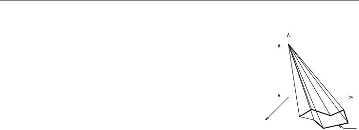
PYRAMID
PYRAMID n, h, mask, x1, y1, s1, ... xn, yn, sn
Pyramid based on a polyline in the x-y plane. The peak of the pyramid is located at (0, 0, h). |
|
|
|
|
|
Z |
|
|
|
|
|
|
|
|
|
|
|
|
|
||
n: number of polyline nodes. |
|
|
|
|
|
|
|
|
|
|
mask: controls the existence of the bottom and (in the case of an open polyline) side polygon. |
|
|
|
|
|
|
|
|
|
|
si: status of the lateral edges. |
|
h |
|
|
|
|
|
|
||
Parameter restrictions: |
|
|
|
|
|
|
|
|
|
|
h > 0 and n > 2 |
|
|
|
|
|
|
|
|
|
|
Masking: |
|
|
|
|
|
|
|
|
Y |
|
|
|
|
|
|
|
|
|
|||
mask = j1 + 4*j3 + 16*j5 |
|
|
|
|
|
|
j3 |
|
|
|
|
|
|
|
|
|
|
|
|
|
|
where j1, j3, j5 can be 0 or 1. |
X |
|
|
|
|
n |
1 |
j1 |
||
j1 |
(1): base surface is present. |
|
|
|
|
|
j5 |
|||
j3 |
(4): side (closing) surface is present. |
|
|
|
|
|
|
|
2 |
|
|
|
|
|
|
|
|
|
|
|
|
j5 |
(16): base edges are visible. |
|
|
|
|
|
|
|
|
|
Status values:
0:lateral edges starting from the node are all visible.
1:lateral edges starting from the node are used for showing the contour.
Additional status codes allow you to create segments and arcs in the planar polyline using special constraints.
See “Additional Status Codes” on page 141 for details.
ArchiCAD 11 GDL Reference Guide |
67 |
3D Shapes
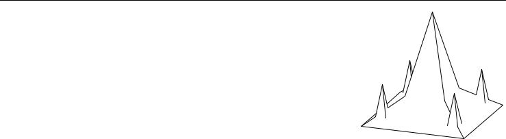
Example:
PYRAMID 4, 1.5, 1+4+16, -2, -2, 0, -2, 2, 0, 2, 2, 0, 2, -2, 0
PYRAMID 4, 4, 21, -1, -1, 0, 1, -1, 0, 1, 1, 0, -1, 1, 0
ADDX -1.4
ADDY -1.4
GOSUB 100
ADDX 2.8
GOSUB 100
ADDY 2.8
GOSUB 100
ADDX -2.8
GOSUB 100 END
100:
PYRAMID 4, 1.5, 21, -0.25, -0.25, 0, 0.25, -0.25, 0, 0.25, 0.25, 0, -0.25, 0.25, 0
RETURN
68 |
ArchiCAD 11 GDL Reference Guide |
3D Shapes
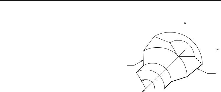
REVOLVE
REVOLVE n, alpha, mask, x1, y1, s1, ... xn, yn, sn
Surface generated by rotating a polyline defined in the x-y plane around the x |
|
|
|
Z |
|
axis. |
|
|
|
|
|
n: number of polyline nodes. |
|
|
|
|
|
alpha: sweep angle in degrees. |
|
|
|
|
|
mask: controls the existence of the bottom, top and (in the case of alpha |
|
|
|
|
|
< 360°) side polygons. |
|
|
j1 |
|
|
|
|
|
|
|
|
|
|
|
|
|
|
si: status of the latitudinal arcs. |
|
|
|
Y |
|
|
j4 |
n |
|||
Parameter restrictions: |
|
|
|
||
j6 |
|
|
|||
n >= 2 |
|
|
|||
|
|
|
|
|
|
yi >= 0.0 |
|
|
j3 |
j5 |
|
yi and yi + 1 (i.e., the y value of two neighboring nodes) cannot be zero |
|
alpha |
|
|
|
at the same time. |
|
|
|
||
|
j2 |
|
|
||
Masking: |
2 |
|
|
||
|
|
|
|
|
|
mask = j1 + 2*j2 + 4*j3 + 8*j4 + 16*j5 + 32*j6 + |
|
1 |
|
|
|
64*j7 |
|
|
|
|
|
where j1, j2, j3, j4, j5, j6, j7 can be 0 or 1. j1 (1): base surface is present.
j2 (2): top surface is present.
j3 (4): side surface is present at initial angle.
j4 (8): side surface is present at final angle.
j5 (16): edges on side surface at initial angle are visible. j6 (32): edges on side surface at final angle are visible.
j7 (64): cross-section edges are visible, surface is not smooth.
Status values:
0:latitudinal arcs starting from the node are all visible.
1:latitudinal arcs starting from the node are used for showing the contour.
ArchiCAD 11 GDL Reference Guide |
69 |

3D Shapes
2: when using ArchiCAD/ArchiFM or Z-buffer Rendering Engine and setting Smooth Surfaces, the latitudinal edge belonging to this point defines a break. This solution is equivalent to the definition of additional nodes. The calculation is performed by the compiler. With other rendering methods, it has the same effect as using 0.
Additional status codes allow you to create segments and arcs in the planar polyline using special constraints.
See “Additional Status Codes” on page 141 for details.
REVOLVE{2} n, alphaOffset, alpha, mask, siedMat, x1, y1, s1, mat1, ...xn, yn, sn, matn
Advanced version of REVOLVE, where the start angle and the face materials are conrolable. alphaOffset: sweep start angle
alpha: sweep angle length in degrees, may be negative sideMat: material of the closing faces
mati: material of the face generated from the i-th edge
Examples:
70 |
ArchiCAD 11 GDL Reference Guide |
3D Shapes
ROTY -90
REVOLVE 22, 360, 1+64, 0, 1.982, 0, 0.093, 2, 0, 0.144, 1.845, 0, 0.220, 1.701, 0, 0.318, 1.571, 0, 0.436, 1.459, 0, 0.617, 1.263, 0, 0.772, 1.045, 0, 0.896, 0.808, 0, 0.987, 0.557, 0, 1.044, 0.296, 0, 1.064, 0.030, 0, 1.167, 0.024, 0, 1.181, 0.056, 0, 1.205, 0.081, 0, 1.236, 0.096, 0, 1.270, 0.1, 0, 1.304, 0.092, 0, 1.333, 0.073, 0, 1.354, 0.045, 0, 1.364, 0.012, 0, 1.564, 0, 0
ArchiCAD 11 GDL Reference Guide |
71 |