

8F - 14 AUDIO SYSTEM
CONDITION: ALL SPEAKERS NON-OPERATIVE
²Check radio for being ON, are the display lights on
²Radio not ON, refer to Radio Diagnosis
²Check Amplifier Connectors and wires for proper connection
²Check pin 9 and pin 27 for battery voltage
²If voltage OK replace amplifier
²If pin 27 has battery voltage and pin 9 has 0 voltage. Refer to Power Antenna Diagnosis and test voltage at antenna relay.
²If pin 9 has battery voltage and pin 27 has 0 voltage. Check pin 27 for short to ground.
²If shorted to ground repair wire
²If no short to ground check fuse cavity number 16 for blown fuse.
²If fuse blows again replace amplifier
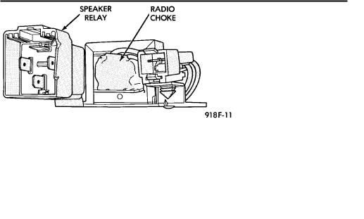
RELAY/CHOKEÐINFINITY SPEAKER
No Bass, test across the connector for continuity. If no continuity Replace Relay/Choke Assembly (Fig. 36).
Ä
LOCATION
(1)AA and AP Bodies attached to the reinforcement above glove box.
(2)AG and AJ Bodies attached to the dimmer module bayonet bracket on the bulkhead behind the glove box.
Fig. 36 Relay/Choke Assembly
COMPACT DISC PLAYER
WARNING: USE OF THE CONTROLS, ADJUSTMENTS, OR SERVICE PROCEDURES NOT SPECIFIED HERE OR IN THE OWNER MANUAL MAY RESULT IN HAZARDOUS RADIATION EXPOSURE. REPAIR PROCEDURES SHOULD ONLY BE PERFORMED BY A TRAINED TECHNICIAN.
DIAGNOSIS TEST
Power to the compact disc player is supplied by the radio through the CD interface cable. The compact disc player will only work with the radio system turned ON. When a compact disc is inserted with the label side facing up, the disc is automatically loaded and will begin to play.
The CD player may eject the disc with a display of E under the following conditions:
²The surface of the disc is dirty or wet
²The disc was inserted with the label side facing down
²The disc is defective
²The CD player may skip or mute while playing a disc under severe vibration conditions example pot holes, railroad tracks, etc.
²If the CD player becomes too hot at temperatures above 60°C (100 °F) the CD player will shut down with a display of HOT until it cools down. Refer to the compact disc player diagnosis chart (Fig. 37).
COMPACT DISC PLAYER REPLACEMENT
(1)Remove center instrument panel bezel by pulling toward the rear of the car.
(2)Remove two screws attaching disc player to console (Fig. 38).
(3)Pull disc player out of console and disconnect interface cable.
(4)To install compact disc player, above the removal procedures.

Ä |
|
AUDIO SYSTEM 8F - 15 |
|
Fig. 37 Compact Disc Player Diagnosis
Fig. 38 Compact Disc Player