

Ä |
|
POWER MIRRORS 8T - 1 |
|
POWER MIRRORS
CONTENTS
|
page |
AUTOMATIC DAY/NIGHT INSIDE MIRROR |
. . . . . 6 |
AUTOMATIC DAY/NIGHT INSIDE MIRROR WITH |
|
ULTRALIGHT HEADLAMP CONTROL . . . |
. . . . . 7 |
GENERAL INFORMATION . . . . . . . . . . . . . . |
. . . . 1 |
HEATED MIRROR . . . . . . . . . . . . . . . . . . . . |
. . . . 2 |
INSIDE MIRROR/READING LAMPS BULB/LENS |
|
REPLACEMENT . . . . . . . . . . . . . . . . . . . . |
. . . . 6 |
INSIDE MIRROR/READING LAMPS |
|
REPLACEMENT . . . . . . . . . . . . . . . . . . . . |
. . . . 6 |
MIRROR ASSEMBLY REPLACEMENT Ð |
|
AA BODY . . . . . . . . . . . . . . . . . . . . . . . . . |
. . . . 4 |
MIRROR ASSEMBLY REPLACEMENT Ð |
|
AC AND AY BODIES . . . . . . . . . . . . . . . . . |
. . . . 5 |
MIRROR ASSEMBLY REPLACEMENT Ð |
|
AG BODY . . . . . . . . . . . . . . . . . . . . . . . . . |
. . . . 4 |
GENERAL INFORMATION
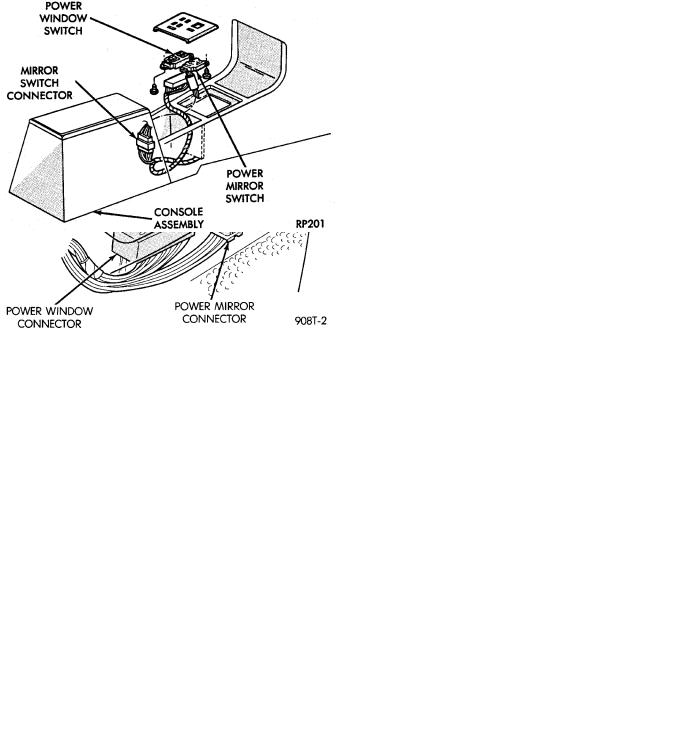
Electrically operated power mirrors are available on all car lines. The mirrors are controlled by a single switch assembly located either on the driver's door trim panel or on the center console.
There are three types of switches currently used, each uses a L (left) R (right) for mirror selection (Fig. 1). Type I, which uses a rocker for mirror selection and four buttons for mirror movement direction. Type II, uses a toggle switch which is rotated clockwise for the Right mirror or counterclockwise for the Left mirror selection,
|
page |
MIRROR ASSEMBLY REPLACEMENT Ð |
|
AJ BODY . . . . . . . . . . . . . . . . . . . . . . . . . . . |
. . 4 |
MIRROR ASSEMBLY REPLACEMENT Ð |
|
AP BODY . . . . . . . . . . . . . . . . . . . . . . . . . . . |
. . 5 |
MIRROR MOTOR TEST PROCEDURE . . . . . . . |
. . 2 |
MIRROR SWITCH REPLACEMENT Ð AA BODY . 3 |
|
MIRROR SWITCH REPLACEMENT Ð |
|
AC AND AY BODIES . . . . . . . . . . . . . . . . . . . |
. . 4 |
MIRROR SWITCH REPLACEMENT Ð |
|
AG AND AJ BODIES . . . . . . . . . . . . . . . . . . . |
. . 4 |
MIRROR SWITCH REPLACEMENT Ð AP BODY . 4 |
|
MIRROR SWITCH TEST PROCEDURE . . . . . . |
. . 2 |
TEST PROCEDURES . . . . . . . . . . . . . . . . . . . . |
. . 2 |
and moved UP, DOWN, LEFT or RIGHT for mirror movement direction. Type III, uses a paddle knob which is moved Left or Right for mirror selection and four buttons for mirror movement direction.
The motors which operate the mirrors are part of the mirror assembly and cannot be replaced separately.
All vehicles are equipped with an Ignition-Off Draw Connector which is used when the vehicles are originally shipped from the factory. This connector, which is located near the battery, helps to prevent
Fig. 1 Power Mirror Switches
8T - 2 POWER MIRRORS |
|
Ä |
|
battery discharge during storage. For specific connector type and location, refer Group 8W, Wiring Diagrams.
This connector is included in the power mirror circuitry except, for AC and AY body and should be checked if the mirrors are inoperative.
MIRROR MOTOR TEST PROCEDURE
(1)Remove power mirror switch from mounting position.
(2)Disconnect switch wiring harness at connector. In the case of memory mirrors, (green 8-way mirror connector and memory switch in drivers door panel), the switch wiring disconnects from the cowl top harness rather than the mirror harness.
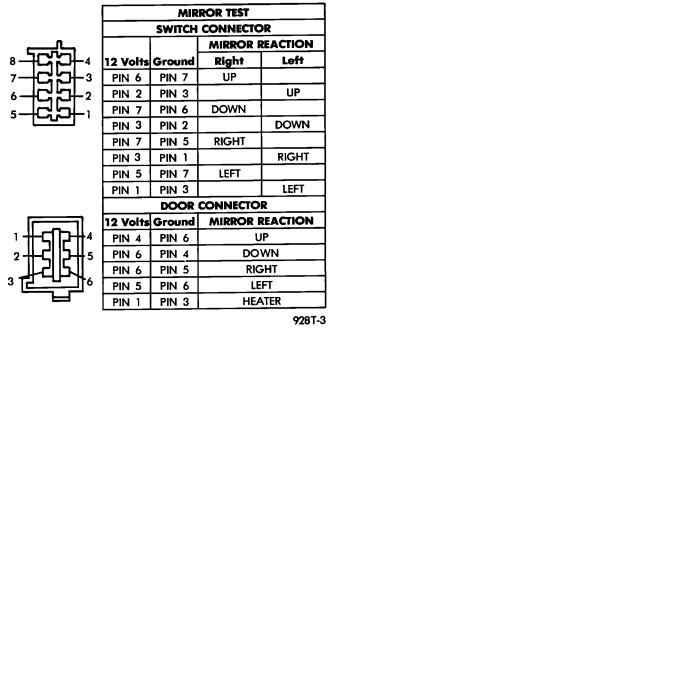
(3)Using two jumper wires, one connected to a 12 volt source, and the other connected to a good body ground. Refer to the Mirror Test (Fig. 2 through 5) for appropriate switch style, and for pin numbers.
Fig. 2 MIRROR TEST Ð AP Body
(4) If results shown in the Fig. 2 through 5 are not obtained, check for broken or shorted circuit, or replace mirror assembly as necessary.
MIRROR SWITCH TEST PROCEDURE
(1)Remove power mirror switch from mounting position.
(2)Disconnect wiring harness at switch connector.
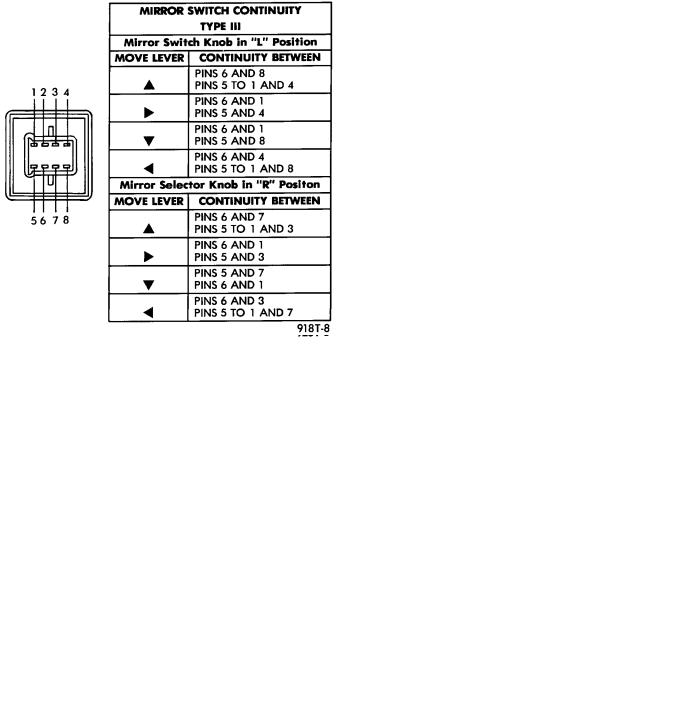
(3)Using an ohmmeter, test for continuity between the terminals of the switch as shown in the Mirror Switch Continuity for appropriate switch style (Fig. 6 through 8).
(4)If results shown in the Fig. 5, 6 and 7 are not obtained, replace the switch.
Fig. 3 MIRROR TEST Ð AA Body
Fig. 4 MIRROR TEST Ð AC and AY Bodies
HEATED MIRROR
Heated mirrors are available on all car lines except AP Body, with Power Mirrors and Rear Window Defogger only. The heated mirror is controlled by the rear window defogger switch. Only time that the heated mirror is on is when the rear window defogger is on.
TEST PROCEDURES
(1)The mirror should be warm to the touch.
(a)If not check fuses.
(b)Test voltage at rear window defogger switch.
Ä |
|
POWER MIRRORS 8T - 3 |
|
Fig. 5 MIRROR TEST Ð AG and AJ Bodies
Fig. 6 Type I Mirror Switch Test
²If no voltage repair wire.
²Apply voltage to one wire and ground the other, refer to Fig. 2 through 5 for pin numbers. Mirror should become warm to the touch.
²If not remove mirror glass and test the wires for continuity. If no continuity repair wires.
²If wires are OK, replace mirror glass.
²To test defogger switch refer to Group 8N, Rear Window Defogger, Control Switch/Timer Relay Module Test.
Fig. 7 Type II Mirror Switch Test
Fig. 8 Type III Mirror Switch Test
MIRROR SWITCH REPLACEMENT Ð AA BODY
(1)Remove door trim panel.
(2)Remove set screw from pillar trim bezel.
(3)Remove pillar trim bezel retaining screws.
(4)Disconnect switch wiring (Fig. 9).
(5)Remove switch from switch bezel.
(6)For installation, reverse above procedure.
8T - 4 POWER MIRRORS |
|
Ä |
|
Fig. 9 Power Mirror Switch Ð AA Body
MIRROR SWITCH REPLACEMENT Ð AG AND AJ BODIES
(1) Carefully pry switch from switch bezel (Fig. 10).
Fig. 10 Power Mirror Switch Ð AG, and AJ Bodies
(2)Remove switch wiring connector.
(3)For installation, reverse above procedure.
MIRROR SWITCH REPLACEMENT Ð AP BODY
(1)Remove power mirror switch bezel from mounting position (Fig. 11).
(2)Turn bezel over and remove two switch retaining screws.
Fig. 11 Power Mirror Switch Ð AP Body
(3)Disconnect wiring at switch connector.
(4)Remove switch from vehicle.
(5)For installation, reverse above procedure.
MIRROR SWITCH REPLACEMENT Ð AC AND AY BODIES
(1)Remove door trim panel.
(2)Remove three pillar trim bezel retaining screws and pull bezel from door.
(3)Loosen remote control switch retaining screw and pull switch from bezel.
(4)Disconnect switch wiring at connector near bottom of door and pull switch and harness from door (Fig. 12).
(5)For installation, reverse above procedure.
MIRROR ASSEMBLY REPLACEMENT Ð AA BODY
(1)Remove door trim panel.
(2)Remove switch set screw from door pillar trim.
(3)Remove two pillar trim bezel screws and remove bezel (Fig. 13).
(4)Disconnect mirror wiring connector.
(5)Remove three mirror retaining nuts and pull mirror and harness from door.
(6)For installation, reverse above procedure. Test operation of mirror before installing door trim panel.
MIRROR ASSEMBLY REPLACEMENT Ð AG BODY
(1)Remove door trim panel.
(2)Disconnect mirror wiring at connector (Figs. 14 and 15).
(3)Remove plugs used to conceal mirror mounting
nuts.
(4)Remove mirror mounting nuts and release mirror from door.
(5)For installation, reverse above procedure. Test mirror for proper operation before installing door trim panel.
MIRROR ASSEMBLY REPLACEMENT Ð AJ BODY
(1) Remove door trim panel.
Ä |
|
POWER MIRRORS 8T - 5 |
|
Fig. 12 Power Mirror Switch and Wiring Ð AC and
AY Bodies
Fig. 13 Power Mirror Assembly Ð AA Body
(2)Remove door speaker and disconnect mirror wiring connectors (Fig. 16).
(3)Remove plugs used to conceal mirror mounting
nuts.
(4)Remove mirror mounting nuts and release mirror from door.
Fig. 14 Power Mirror Wiring Ð AG Body
Fig. 15 Power Mirror AssemblyÐAG Body
(5) For installation, reverse above procedure. Test mirror for proper operation before installing door trim panel.
MIRROR ASSEMBLY REPLACEMENT Ð AP BODY
(1)Remove door trim panel.
(2)Disconnect wiring at connector (Figs. 17 and
18).
(3)Remove door bezel and small plug to gain access to mirror retaining nuts.
(4)Remove three mirror retaining nuts and remove mirror from vehicle.
(5)For installation, reverse above procedure. Test mirror for proper operation before installing door trim panel.
MIRROR ASSEMBLY REPLACEMENT Ð AC AND AY BODIES
(1)Remove door trim panel.
(2)Remove three pillar trim bezel retaining screws and pull bezel from door.

8T - 6 POWER MIRRORS |
|
Ä |
|
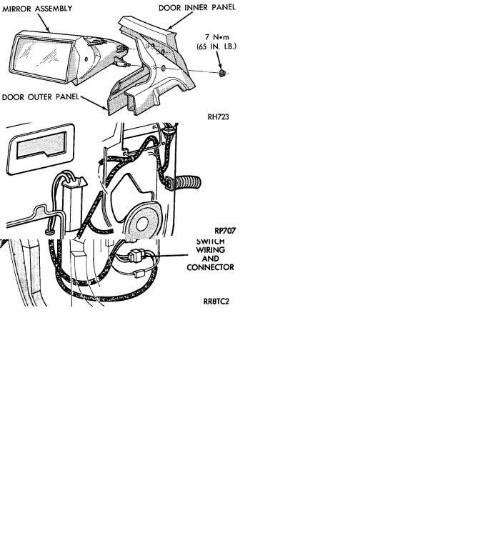
Fig. 16 Power Mirror AssemblyÐAJ Body
Fig. 17 Power Mirror WiringÐAP Body
(3)Disconnect mirror wiring connector near bottom of door (Fig. 19).
(4)Remove two mirror retaining nuts and screw one, and pull mirror and harness from door.
(5)For installation, reverse above procedure. Test mirror for proper operation before installing door trim panel.
INSIDE MIRROR/READING LAMPS REPLACEMENT
(1)Release locking tab on front side of mirror stay by pushing down. While holding tab down, pull mirror rearward to remove (Fig. 20).
(2)Remove visor center attaching clips.
(3)Remove header end caps.
Fig. 18 Power Mirror Assembly Ð AP Body
Fig. 19 Power Mirror Assembly Ð AC and AY Body
(4)Remove header trim.
(5)Disconnect wiring connector.
(6)For installation, reverse above procedure. Ensure the mirror is fully locked into place.
INSIDE MIRROR/READING LAMPS BULB/LENS REPLACEMENT
(1)Place a small thin blade tool in the notch at the outside end of the lens housing and pry off the lens housing.
(2)Remove lamp socket from lens housing. Remove bulb socket and replace if necessary.
(3)Remove lens by applying pressure on locking tabs to remove lens.
(4)Replacing lens, set into place apply pressure until it is locked into position.
(5)For installation, reverse above procedure.
AUTOMATIC DAY/NIGHT INSIDE MIRROR
Operational test:
²Turn ignition switch to the ON position with the vehicle in park (Fig. 21).
²Place mirror switch in the high position.
Ä |
|
POWER MIRRORS 8T - 7 |
|
(5) If not refer, to Wiring Diagrams manual to test the circuits.
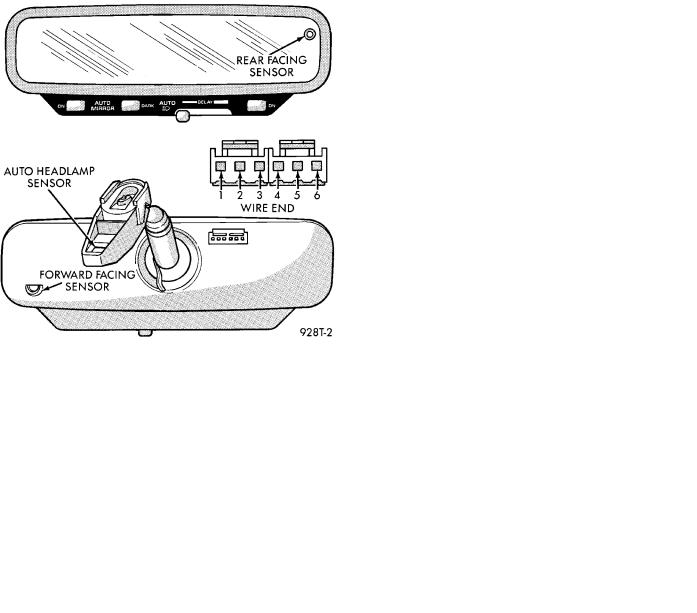
AUTOMATIC DAY/NIGHT INSIDE MIRROR WITH
ULTRALIGHT HEADLAMP CONTROL
CAUTION: When JUMP STARTING the vehicle, before cranking engine turn ignition ON and turn OFF the Automatic Headlamp Control.
The mirror automatically reduces the amount to headlamp glare from rear approaching traffic and provides automatic headlamp control (Fig. 22).
Fig. 20 Header Mirror/Reading Lamps
Fig. 21 Automatic Day / Night Mirror
²Cover the forward facing sensor with dark cloth to keep out any ambient light.
²Shine a light into the rear facing sensor, watch to see if the mirror darkens.
With the mirror darkened, place the vehicle in reverse, the mirror should return to its normal condition.
If the above conditions are met the mirror is operating properly.
²If not test voltage.
Test three way connector harness. Refer to Fig. 21.
(1)Pin 1 Ignition Switch in run position, should have battery voltage.
(2)Pin 2 Should have continuity to Ground.
(3)Pin 3 When the transmission is in reverse, should have battery voltage.
(4)If test is OK replace Mirror.
Fig. 22 Automatic Day / Night Mirror with Ultralight Headlamp Control
SELF DIAGNOSTIC MODEÐOPERATIONAL TEST:
(1)Place shift selector in park (P) or Neutral (N) position. With ignition OFF, press and hold AUTO MIRROR and AUTO LAMP (headlamp) buttons, turn ignition switch ON. When LED indicators start flashing, release buttons.
(a)The button LED indicators should flash for above five seconds.
²AUTO MIRROR
²DARK
²AUTO LAMP
(b)If they continue to flash much longer than five seconds, the mirror assembly is defective.
(2)The headlamps and parking lamps should turn ON for above five seconds.
²AUTO MIRROR LED
²DARK LED
²AUTO LAMP LED
²The LED indicators blink for about 5 seconds.