

Ä |
|
MANUAL TRANSAXLE CLUTCH 6 - 1 |
|
MANUAL TRANSAXLE CLUTCH
CONTENTS
|
page |
CLEANING PRECAUTIONS . . . . . . . . . . . . . . . |
. . 5 |
CLUTCH CABLE MECHANISM . . . . . . . . . . . . |
. . 1 |
CLUTCH CABLE REPLACEMENT . . . . . . . . . . |
. . 1 |
CLUTCH CHATTER COMPLAINTS . . . . . . . . . . |
. . 1 |
CLUTCH DISC REPLACEMENT . . . . . . . . . . . . |
. . 4 |
GENERAL INFORMATION
Throughout this group, references may be made to a particular vehicle by letter or number designation. A chart showing the breakdown of these designations is included in the Introduction Section at the front of this service manual.
The clutch used in all models are a single, dry disc type with no adjustment for wear being provided in the clutch itself.
The clutch pedal is connected to the torque shaft through a cable and lever.
The upper end of the clutch pedal pivots in the pedal bracket on two nylon bushings. These bushings do not require periodic lubrication.
CLUTCH CHATTER COMPLAINTS
For all clutch chatter complaints, do the following:
(1)Check for loose, misaligned, or broken engine and transmission mounts. If present, they should be corrected at this time. Test vehicle for chatter. If chatter is gone, there is no need to go any further. If chatter persists:
(2)Check to see if clutch cable routing is correct and operates smoothly.
(3)Check for loose connections in drive train. Correct any problems and determine if clutch chatter complaints has been satisfied. If not,
(4)Remove transaxle. See Group 21, Manual Transaxle, for procedure.
(5)Check to see if the release bearing is sticky or binding. Replace bearing, if needed.
(6)Check linkage for excessive wear on bushings. Replace all worn parts. A small amount of bearing grease between the cross shaft bushings and the shaft is beneficial, but not required.
(7)Check flywheel and clutch pressure plate for contamination (dirt, oil) or scored. Replace flywheel and/or pressure plate, if required.
(8)Check to see if the clutch disc hub splines are damaged. Replace with new disc.
(9)Check input shaft splines for damage. Replace if necessary.
(10)Check for uneven wear on clutch fingers.
|
page |
CLUTCH/STARTER INTERLOCK SWITCH . . . . |
. . 3 |
EXCESSIVE CLUTCH SPIN TIME/CLASH INTO |
|
REVERSE COMPLAINTS . . . . . . . . . . . . . . . |
. . 1 |
GENERAL INFORMATION . . . . . . . . . . . . . . . . |
. . 1 |
RELEASE BEARING AND FORK . . . . . . . . . . . |
. . 5 |
EXCESSIVE CLUTCH SPIN TIME/CLASH INTO REVERSE COMPLAINTS
For all excessive clutch spin time/clash into reverse complaints, do the following:
(1)Depress clutch pedal to floor and hold. After three seconds, shift to reverse. If clash is present, clutch has excessive spin time.
(2)Remove transaxle. See Group 21, Manual Transaxle, for procedure.
(3)Check the input shaft spline, clutch disc splines and release bearing for dry rust. If present, clean rust off and apply a light coat of bearing grease to the input shaft splines. Apply grease on the input shaft splines only where the clutch disc slides.
(4)Check to see if the clutch disc hub splines are damaged, replace with new disc if required.
(5)Check the input shaft for damaged splines. Replace as necessary.
(6)Install clutch assembly and transaxle.
CLUTCH CABLE MECHANISM
The manual transaxle clutch release system has a unique self-adjusting mechanism to compensate for clutch disc wear. This adjuster mechanism is located within the clutch pedal. The preload spring maintains tension on the cable. This tension keeps the clutch release bearing continuously loaded against the fingers of the clutch cover assembly.
When the pedal is depressed, teeth on the adjuster and the positioner engage and pull the release cable. A spring located behind the adjuster ensures proper tooth engagement.
When the pedal is released, the adjuster contacts the bumper. This separates the adjuster and positioner teeth, allowing the preload spring to function.
CLUTCH CABLE REPLACEMENT
(1) Remove retainer from clutch release lever at transaxle by pulling on the tail of the ball stud (Fig. 1).

6 - 2 MANUAL TRANSAXLE CLUTCH |
|
Ä |
|
Fig. 1 Self-Adjusting Clutch Release Mechanism
Ä |
|
MANUAL TRANSAXLE CLUTCH 6 - 3 |
|
(2)Pry out ball end of cable from positioner adjuster and remove cable, passing it through the hoop in the shock tower mounting bracket.
(3)Inspect cable for wear and contamination. The inner cable strand should move smoothly inside the cable housing. If cable is worn or damaged, replace the cable. Do not lubricate.
(4)Inspect the clutch pedal and adjuster mechanism for wear. Apply a multipurpose lubricant on parts indicated (Fig. 1).
(5)To install, reverse procedure of steps (3) through (1).
(6)After installation, push and lift the clutch pedal 2 or 3 times to allow adjuster mechanism to function.
(7)Check clutch pedal starter interlock switch operation.
CLUTCH/STARTER INTERLOCK SWITCH
The clutch/starter interlock switch functions as a safety interlock device. It prevents possible engine cranking with the manual transmission in gear.
The clutch switch is wired in series between the starter relay coil and the ignition switch.
The clutch/starter interlock switch is mounted to a bracket located next to the clutch pedal. The switch is held in place by two plastic wing tabs.
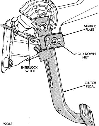
The clutch/starter interlock switch has an adjustable striker plate. The striker plate is located on the left side of the clutch pedal (Fig. 2).
DIAGNOSIS
Disconnect clutch/starter interlock switch harness from instrument panel wiring harness. Using a ohm meter, check for continuity between the two terminals in the connector on the switch harness. There should be no continuity between the terminals when the switch is in its neutral (fully extended) position. When the switch is depressed more than 1 mm (0.040) the ohm meter should show continuity.
If all ohm meter readings are correct and the switch does not operate correctly, adjustment is required. Refer to Switch Adjustment Procedure to adjust switch.
REMOVAL
(1)Disconnect electrical harness to switch connec-
tor.
(2)Push switch out of mounting bracket and slide wires through slot in bracket.
INSTALLATION
(1)Slide switch wires through slot in switch bracket.
(2)Line up switch tab with slot in switch bracket and push switch into position. Do not pull on the switch wires to seat switch into bracket, switch damage may occur.
Fig. 2 Clutch Interlock Switch and Components
(3) After installation, the switch must be adjusted and checked for proper operation. Refer to Switch Adjustment Procedure.
ADJUSTMENT PROCEDURE
When performing switch adjustment, the floor mat should be removed before beginning adjustment procedures.
(1)Set the park brake.
(2)Disconnect clutch cable at the transaxle end of the cable.
(3)Depress clutch pedal, loosen adjusting nut and slide the striker plate forward to fully compress the interlock switch plunger.
(4)Tighten adjusting nut to 12 NIm (105 in. lbs.).
(5)Reconnect clutch cable.
The interlock switch is now adjusted. A final check is required to insure that the switch is ``made'' below the clutch release point.
(1)With the park brake set and the vehicle IN NEUTRAL turn the key to the start position. The vehicle should not crank. If the vehicle cranks do not continue with this test. Recheck the switch and switch adjustment to determine the cause. If the vehicle does not crank proceed to step 2.
(2)With the park brake set and the vehicle IN GEAR turn the key to the start position.