

serial
.pdfInterfacing the Serial / RS232 Port V5.0 |
http://www.senet.com.au/~cpeacock |
Then DTR, RTS and OUT 2 is taken active by the instruction outportb(PORT1 + 4,0x0B);. Some cards (Both of Mine) require OUT2 active for interrupt requests thus I'm normally always take it high. All that is left now is to set up our interrupts which has be deliberately left to last as to not interrupt our initialization. Our interrupt handler is only interested in new data being available so we have only set the UART to interrupt when data is received.
Main Routine (Loop)
Now we are left with,
do {
if (bufferin != bufferout){
ch = buffer[bufferout]; bufferout++;
if (bufferout == 1024) bufferout = 0; printf("%c",ch);
}
if (kbhit()){
c = getch(); outportb(PORT1, c);
}
} while (c !=27);
which keeps repeating until c = 27. This occurs when the ESC key is hit.
The next if statement checks to see if a key has been hit. (kbhit()) If so, it gets the character using the getch() statement and outputs it to the receiver buffer. The UART then transmits the character to the modem. What we have assumed here, is that the person using the Communications Program can't type as fast as the UART can send. However if the program wishes to send something, then a check should be made to see if BIT 5 of the Line Status Register is set before attempting to send a byte to the transmitter register.
For more information on Interrupts, try Using Interrupts,
http://www.geocities.com/SiliconValley/Bay/8302/interupt.pdf (62k)
Determining the type of UART via software
The type of UART you have installed in your system can be determined without even needing a screwdriver in most cases. As you can see from the Types of UARTs, each UART has minor differences, all we have to do it test these.
The first procedure we do is to set bit 0 to '1' in the FIFO control register. This tries to enable the FIFO buffers. Then we read bits 6 and 7 from the interrupt identification register. If both bits are '1' then the FIFO buffers are enabled. This would mean the UART is a 16550a. If the FIFO's were enabled but not usable then it would be a 16550. If there is no FIFO buffer enabled it is most likely to be a 16450 UART, but could be a 8250, 8250A or 8250B on very old systems.
Interfacing the Serial / RS232 Port V5.0 |
Page 31 |
|
|
Interfacing the Serial / RS232 Port V5.0 |
http://www.senet.com.au/~cpeacock |
AT's have a fast bus speed which the 8250 series of UART can't handle to well thus it is very unlikely to be found in any AT. However if you wish to test for them as well you can follow the same test as above to distinguish 16550's or 16550A's from the rest. If no FIFOs are enabled then a possible UART is the 16450, 8250, 8250A or 8250B. Once it is established the it could be one of these four chips, try writing a byte to the scratch register and then read it back and compare the results. If the results match then you must have a scratch register, if they don't you either don't have a scratch register, or it doesn't work to well.
From the descriptions of the UART above if you read back your byte from the scratch register then the UART must be a 16450 or 8250A. (Both have scratch registers) If you don't read back your byte then it's either a 8250 or 8250B.
The 16750 has 64 byte FIFO's, thus the easiest way to test for it's presence is to enable the 64 byte buffer using the FIFO Control Register and then read back the status of the Interrupt Identification Register. However I have never tested this.
Interfacing the Serial / RS232 Port V5.0 |
Page 32 |
|
|

Interfacing the Serial / RS232 Port V5.0 |
http://www.senet.com.au/~cpeacock |
Part 4 : Interfacing Devices to RS-232 Ports
RS-232 Waveforms
So far we have introduced RS-232 Communications in relation to the PC. RS-232 communication is asynchronous. That is a clock signal is not sent with the data. Each word is synchronized using it's start bit, and an internal clock on each side, keeps tabs on the timing.
Figure 4 : TTL/CMOS Serial Logic Waveform
The diagram above, shows the expected waveform from the UART when using the common 8N1 format. 8N1 signifies 8 Data bits, No Parity and 1 Stop Bit. The RS-232 line, when idle is in the Mark State (Logic 1). A transmission starts with a start bit which is (Logic 0). Then each bit is sent down the line, one at a time. The LSB (Least Significant Bit) is sent first. A Stop Bit (Logic 1) is then appended to the signal to make up the transmission.
The diagram, shows the next bit after the Stop Bit to be Logic 0. This must mean another word is following, and this is it's Start Bit. If there is no more data coming then the receive line will stay in it's idle state(logic 1). We have encountered something called a "Break" Signal. This is when the data line is held in a Logic 0 state for a time long enough to send an entire word. Therefore if you don't put the line back into an idle state, then the receiving end will interpret this as a break signal.
The data sent using this method, is said to be framed. That is the data is framed between a Start and Stop Bit. Should the Stop Bit be received as a Logic 0, then a framing error will occur. This is common, when both sides are communicating at different speeds.
The above diagram is only relevant for the signal immediately at the UART. RS-232 logic levels uses +3 to +25 volts to signify a "Space" (Logic 0) and -3 to -25 volts for a "Mark" (logic 1). Any voltage in between these regions (ie between +3 and -3 Volts) is undefined. Therefore this signal is put through a "RS-232 Level Converter". This is the signal present on the RS-232 Port of your computer, shown below.
Figure 5 : RS-232 Logic Waveform
The above waveform applies to the Transmit and Receive lines on the RS-232 port. These lines carry serial data, hence the name Serial Port. There are other lines on the RS-232 port which, in essence are Parallel lines. These lines (RTS, CTS, DCD, DSR, DTR, RTS and RI) are also at RS-232 Logic Levels.
Interfacing the Serial / RS232 Port V5.0 |
Page 33 |
|
|

Interfacing the Serial / RS232 Port V5.0 |
http://www.senet.com.au/~cpeacock |
RS-232 Level Converters
Almost all digital devices which we use require either TTL or CMOS logic levels. Therefore the first step to connecting a device to the RS-232 port is to transform the RS-232 levels back into 0 and 5 Volts. As we have already covered, this is done by RS-232 Level Converters.
Two common RS-232 Level Converters are the 1488 RS-232 Driver and the 1489 RS-232 Receiver. Each package contains 4 inverters of the one type, either Drivers or Receivers. The driver requires two supply rails, +7.5 to +15v and -7.5 to -15v. As you could imagine this may pose a problem in many instances where only a single supply of +5V is present. However the advantages of these I.C's are they are cheap.
Above: (Figure 6) Pinouts for the MAX-232,
RS-232 Driver/Receiver.
Right: (Figure 7) Typical MAX-232 Circuit.
Another device is the MAX-232. It includes a Charge Pump, which generates +10V and -10V from a single 5v supply. This I.C. also includes two receivers and two transmitters in the same package. This is handy in many cases when you only want to use the Transmit and Receive data Lines. You don't need to use two chips, one for the receive line and one for the transmit. However all this convenience comes at a price, but compared with the price of designing a new power supply it is very cheap.
There are also many variations of these devices. The large value of capacitors are not only bulky, but also expensive. Therefore other devices are available which use smaller capacitors and even some with inbuilt capacitors. (Note : Some MAX-232's can use 1 micro farad Capacitors). However the MAX232 is the most common, and thus we will use this RS-232 Level Converter in our examples.
Making use of the Serial Format
In order to do anything useful with our Serially transmitted data, we must convert it back to Parallel. (You could connect an LED to the serial port and watch it flash if you really want too, but it's not extremely useful). This in the past has been done with the use of UART's. However with the popularity of cheap Microcontroller's, these can be more suited to many applications. We will look into the advantages and disadvantages of each method.
Interfacing the Serial / RS232 Port V5.0 |
Page 34 |
|
|

Interfacing the Serial / RS232 Port V5.0 |
http://www.senet.com.au/~cpeacock |
8250 and Compatible UARTs
We have already looked at one type of UART, the 8250 and compatibles found in your PC. These devices have configuration registers accessible via the data and address buses which have to be initialized before use. This is not a problem if your device which you are building uses a Microprocessor. However if you are making a stand alone device, how are you going to initialize it?
Most Microprocessors / Microcontrollers these days can be brought with build-in Serial Communication Interfaces (SCI). Therefore there is little need to connect a 40 pin 16550 to, for example a 68HC11 when you can buy one built in. If you are still in love with the Z-80 or 8086 then an 16550 may be option! (or if you are like myself, the higher chip count the better. After all it looks more complicated and impressive! - But a headache to debug!)
Figure 8 : Pin Diagrams for 16550, 16450 & 8250 UARTs
For more information on the 16550 and compatible UART's see The UART (8250 and Compatibles) in Part One of this tutorial or consult the PC16550D data sheet from National Semiconductor (http://www.natsemi.com)
Interfacing the Serial / RS232 Port V5.0 |
Page 35 |
|
|

Interfacing the Serial / RS232 Port V5.0 |
http://www.senet.com.au/~cpeacock |
CDP6402, AY-5-1015 / D36402R-9 etc UARTs
There are UARTs such as the CDP6402, AY-5- 1015 / D36402R-9 and compatibles. These differ from the 8250 and compatibles, by the fact that they have separate Receive and Transmit data buses and can be configured by connecting certain pins to various logic levels. These are ideal for applications where you don't have a Microprocessor available. Such an example is if you want to connect a ADC0804 (Analog to Digital Converter) to the UART, or want to connect a LCD Display to the Serial Line. These common devices use a 8 bit parallel data bus.
|
The CDP6402's Control Register is made up of |
|
Parity Inhibit (PI), Stop Bit Select (SBS), Character |
|
Length Select (CLS1 and 2) and Even Parity Enable |
|
(EPE). These inputs can be latched using the Control |
|
Register Load (CRL) or if you tie this pin high, changes |
Figure 9 : Pinout of CDP6402 |
made to these pins will immediately take effect. |
Pin Number |
Abbr. |
Full Name |
Notes |
|
|
|
|
Pin 1 |
VDD |
+ 5v Supply |
Connect to Supply (VCC +5V) |
|
|
Rail |
|
|
|
|
|
Pin 2 |
NC |
Not |
Not Connected. |
|
|
Connected |
|
|
|
|
|
Pin 3 |
GND |
Ground |
Ground. |
|
|
|
|
Pin 4 |
RRD |
Receiver |
When driven high, outputs RBR8:RBR1 are High |
|
|
Register |
Impedance. |
|
|
Disable |
|
|
|
|
|
Pin 5:12 |
RBR8: |
Receiver |
Receiver's Data Bus |
|
RBR1 |
Buffer |
|
|
|
Register |
|
|
|
|
|
Pin 13 |
PE |
Parity Error |
When High, A Parity Error Has Occurred. |
|
|
|
|
Pin 14 |
FE |
Framing |
When High, A Framing Error Has Occurred. i.e. The |
|
|
Error |
Stop Bit was not a Logic 1. |
|
|
|
|
Pin 15 |
OE |
Overrun |
When High, Data has been received but the nData |
|
|
Error |
Received Reset had not yet been activated. |
|
|
|
|
Interfacing the Serial / RS232 Port V5.0 |
Page 36 |
|
|
Interfacing the Serial / RS232 Port V5.0 |
http://www.senet.com.au/~cpeacock |
Pin 16 |
SFD |
Status Flag |
When High, Status Flag Outputs (PE, FE, OE, DR and |
|
|
Disable |
TBRE) are High Impedance |
|
|
|
|
Pin 17 |
RRC |
Receiver |
x16 Clock input for the Receiver Register. |
|
|
Register |
|
|
|
Clock |
|
|
|
|
|
Pin 18 |
nDRR |
Data |
Active Low. When low, sets Data received Output Low |
|
|
Received |
(i.e. Clears DR) |
|
|
Reset |
|
|
|
|
|
Pin 19 |
DR |
Data |
When High, Data has been received and placed on |
|
|
Received |
outputs RBR8:RBR1. |
|
|
|
|
Pin 20 |
RRI |
Receiver |
RXD - Serial Input. Connect to Serial Port, Via RS-232 |
|
|
Register In |
receiver. |
|
|
|
|
Pin 21 |
MR |
Master Reset |
Resets the UART. UART should be reset after applying |
|
|
|
power. |
|
|
|
|
Pin 22 |
TBRE |
Transmitter |
When High, indicates that Transmitter Buffer Register |
|
|
Buffer |
is Empty, thus all bits including the stop bit have been |
|
|
Register |
sent. |
|
|
Empty |
|
|
|
|
|
Pin 23 |
nTBRL |
Transmitter |
Active Low. When low, data present on TBR8:TBR1 is |
|
|
Buffer Load / |
placed in Transmitter Buffer Register. A Low to High |
|
|
Strobe |
Transition on this pin, then sends the data. |
|
|
|
|
Pin 24 |
TRE |
Transmitter |
When High, Transmitter Register is Empty, thus can |
|
|
Register |
accept another byte of data to be sent. |
|
|
Empty |
|
|
|
|
|
Pin 25 |
TRO |
Transmitter |
TXD - Serial Output. Connect to Serial Port, Via RS- |
|
|
Register Out |
232 Transmitter. |
|
|
(TXD) |
|
|
|
|
|
Pin 26:33 |
TBR8: |
Transmitter |
Data Bus, for Transmitter. Place Data here which you |
|
TBR1 |
Buffer |
want to send. |
|
|
Register |
|
|
|
|
|
Pin 34 |
CRL |
Control |
When High, Control Register (PI, SBS, CLS2, CLS1, |
|
|
Register |
EPE) is Loaded. Can be tied high, so changes on these |
|
|
Load |
pins occur instantaneously. |
|
|
|
|
Pin 35 |
PI |
Parity Inhibit |
When High, No Parity is Used for Both Transmit and |
|
|
|
Receive. When Low, Parity is Used. |
|
|
|
|
Pin 36 |
SBS |
Stop Bit |
A High selects 2 stop bits. (1.5 for 5 Character Word |
|
|
Select |
Lengths) A Low selects one stop bit. |
|
|
|
|
Interfacing the Serial / RS232 Port V5.0 |
Page 37 |
|
|
Interfacing the Serial / RS232 Port V5.0 |
http://www.senet.com.au/~cpeacock |
||||
|
|
|
|
|
|
|
Pin 37:38 |
CLS2: |
Character |
Selects Word Length. 00 = 5 Bits, 01 = 6 Bits, 10 = 7 |
|
|
|
CLS1 |
Length Select |
Bits and 11 = 8 Bits. |
|
|
|
|
|
|
|
|
Pin 39 |
EPE |
Even Parity |
When High, Even Parity is Used, When Low, Odd |
|
|
|
|
Enable |
Parity is Used. |
|
|
|
|
|
|
|
|
Pin 40 |
TRC |
Transmitter |
16x Clock input for Transmitter. |
|
|
|
|
Register |
|
|
|
|
|
Clock |
|
|
|
|
|
|
|
|
Table 18 : Pin Description for CDP6402, AY-5-1015 / D36402R-9 and compatible UART's
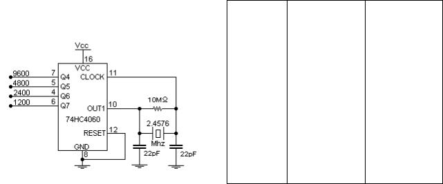
However one disadvantage of these chips over the 8250's is that these UART's have no inbuilt Programmable Baud Rate Generator, and no facility to connect a crystal directly to it. While there are Baud Rate Generator Chips such as the AY-5-8116, a more cheaper (and common) alternative is the 74HC4060 14-bit Binary Counter and Oscillator.
The 74HC4060, being a 14 bit binary counter/divider only has outputs for some of it's stages. Only Q4 to Q14 is available for use as they have external connections. This means higher Baud Rates are not obtainable from common crystals, such as the 1.8432 Mhz and 2.4576 Mhz. The UART requires a clock rate 16 times higher than the Baud Rate you will be using. eg A baud rate of 9600 BPS requires a input clock frequency of 153.6 Khz.
Output |
1.8432Mhz |
2.4546Mhz |
|
|
|
Out 2 |
115.2 KBPS |
153.6 KBPS |
|
|
|
Q4 |
7200 BPS |
9600 BPS |
|
|
|
Q5 |
3600 BPS |
4800 BPS |
|
|
|
Q6 |
1800 BPS |
2400 BPS |
|
|
|
Q7 |
900 BPS |
1200 BPS |
|
|
|
Q8 |
450 BPS |
600 BPS |
|
|
|
Q9 |
225 BPS |
300 BPS |
Figure 10 : Baud Rate Generator using a 74HC4060
Table 19 : Possible Baud Rates using a 74HC4060
The 1.8432 Mhz crystal gives some unfamiliar Baud Rates. While many of these won't be accepted by terminal programs or some hardware, they are still acceptable if you write your own serial programs. For example the PC's baud rate divisor for 7200 BPS is 16, 3600 BPS is 32, 1800 BPS is 64 etc. If you require higher speeds, then it is possible to connect the UART to the OUT2 pin. This connection utilizes the oscillator, but has no frequency division applied. Using OUT2 with a 1.8432 Mhz crystal connected gives a baud rate of 115,200 BPS. The CMOS CDP6402 UART can handle up to 200 KBPS at 5 volts, however your MAX-232 may be limited to 120 KBPS, but is still within range.
Interfacing the Serial / RS232 Port V5.0 |
Page 38 |
|
|

Interfacing the Serial / RS232 Port V5.0 |
http://www.senet.com.au/~cpeacock |
Microcontrollers
It is also possible to use microcontrollers to transmit and receive Serial data. As we have already covered, some of these MCU's (Micro Controller Units) have built in UART's among other things. Take the application we have used above. We want to monitor analog voltages using a ADC and then send them serially to the PC. If the Microcontroller also has a ADC built in along with the UART or SCI, then we could simply program the device and connect a RS-232 Line Driver. This would minimize your chip count and make your PCB much smaller.
Take the second example, displaying the serial data to a common 16 character x 2 line LCD display. A common problem with the LCD modules, is they don't accept cartridge returns, line-feeds, form-feeds etc. By using a microcontroller, not only can you emulate the UART, but you can also program it to clear the screen, should a form-feed be sent or advance to the next line should a Line-feed be sent.
The LCD example also required some additional logic (An Inverter) to reset the data receive line on the UART, and provide a -ve edge on the enable of the LCD to display the data present on the pins. This can all be done using the Microcontroller and thus reducing the chip count and the cost of the project.
Talking of chip count, most Microcontrollers have internal oscillators thus you don't require the 74HC4060 14 Bit Binary Counter and Oscillator. Many Microcontrollers such as the 68HC05J1A and PIC16C84 have a smaller pin count, than the 40 Pin UART. This not only makes the project smaller in size, it reduces complexity of the PCB.
But there are also many disadvantages of the Microcontroller. The major one, is that you have to program it. For the hobbyist, you may not have a development system for a Microcontroller or a method of programming it. Then you have to learn the micro's code and work out how to tackle the problem. At least with the UART, all you did was plug it in, wire it up and it worked. You can't get much simpler that that.
So far we have only discussed Full Duplex Transmission, that is that we can transmit and receive at the same time. If our Microcontroller doesn't have a SCI then we can Emulate a RS232 port using a Parallel line under software control. However Emulation has it's dis-advantages. It only supports slow transmission speeds, commonly 2400, 9600 or maybe even 19,200 BPS if you are lucky. The other disadvantage is that it's really only effective in half duplex mode. That is, it can only communicate in one direction at any one given time. However in many applications this is not a problem.
As there are many different types of Micro-Controllers all with their different instruction sets, it is very hard to give examples here which will suit everyone. Just be aware that you can use them for serial communications and hopefully at a later date, I can give a limited number of examples with one micro.
Interfacing the Serial / RS232 Port V5.0 |
Page 39 |
|
|

Interfacing the Serial / RS232 Port V5.0 |
http://www.senet.com.au/~cpeacock |
Craig Peacock’s Interfacing the PC
http://www.senet.com.au/~cpeacock
http://www.geocities.com/SiliconValley/Bay/8302/
Copyright 1998 Craig Peacock.
Any errors, ideas, criticisms or problems, please contact the author at cpeacock@senet.com.au 3:10pm Friday 30th January 1998
Interfacing the Serial / RS232 Port V5.0 |
Page 40 |
|
|