

thin_section_microscopy
.pdfRaith, Raase, Reinhardt – January 2011
Guide to Thin Section Microscopy |
Microscope |
|
|
|
|
Figure 1.1-3: Two-step magnification of a crystal by the compound microscope.
5

Raith, Raase, Reinhardt – January 2011
 Guide to Thin Section Microscopy Microscope
The total magnification M of a compound microscope is the product of objective magnification (MO) and ocular magnification (ML):
M = MO * ML
Example: A microscope equipped with an objective MO = 50 and an ocular ML = 10 has a final magnification of 50 x 10 = 500.
In modern compound microscopes (with infinity-corrected optical systems) the magnification of the object is performed in a somewhat different way. The specimen is placed in the lower focal plane of the objective, so that its image is projected at infinity. An auxiliary lens (tube lens or telan) placed within the tube between the objective and the eyepiece brings the parallel light rays into focus and produces the real image which then is viewed with the ocular. The infinity-corrected imaging technique allows to insert accessory components such as analyzer, compensators or beam splitters into the light path of parallel rays between the objective and the tube lens with only minimal effects on the quality of the image. It further provides a better correction of spherical and chromatic aberration.
1.2 Objective and ocular (eyepiece)
1.2.1 Objective
The quality of the observed image is largely determined by the objective. The objective is thus a key component in the microscope, being responsible for the primary image, its magnification and the resolution under which fine details of an object can be observed. The ocular merely serves to further magnify the fine details that are resolved in the intermediate image, so that they exceed the angular resolution limits of the human eye and can be viewed at visual angles larger than 1ƍ (Ch. 1.1.1, loupe).
The important properties of an objective are its magnification, its numerical aperture and the degree of aberration correction, whereby the latter two determine the quality of the intermediate image.
Aberration
Simple biconvex lenses produce imperfect, distorted images that show spherical and chromatic aberrations. In modern objectives, such optical aberrations are compensated to a large extent by a combination of converging and diverging lenses that are made of materials with different refractive indices and dispersion. Remaining abberations are compensated by oculars with complementary corrections.
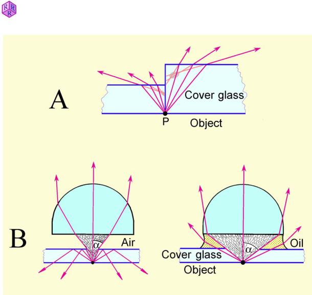
At high magnification and large aperture, the cover glass of thin sections introduces chromatic and spherical aberrations which have an adverse effect on image quality. This is because light rays emerging from an object point P are refracted at the boundary cover glass/air. As a consequence, the backward extensions of the light rays do not focus in a spot, but form a blurry, defocused area (Fig. 1.2-1A, grey areas). With increasing thickness of the cover glass the blurring effect becomes more pronounced. High-power objectives are therefore corrected for this type of cover glass aberration, commonly for a standard glass thickness of 0.17 mm. Hence, the cover glass forms part of the objective system! Any thickness deviating from 0.17 mm affects the intermediate image. Furthermore, if the cover glass is too thick, it may not be possible to focus the specimen using high-power objectives, due to the short free working distances of such objectives (see Table 1).
6
Guide to Thin Section Microscopy |
Microscope |
|
|
|
|
Raith, Raase, Reinhardt – January 2011
Figure 1.2-1: A. Aberration of light rays in the cover glass; B. Aperture of the objective
Aperture and resolution
The numerical aperture (N.A.) of the objective is a measure of the quantity of light taken up by the objective lens. The N.A. is proportional to the angular aperture D of the cone of light rays emitted from a point on the specimen that enters the objective, and to the refractive index n of the medium which separates the specimen from the front lens of the objective (e.g. 1.0 for air, 1.33 for water, and ~1.56 for oil): N.A. = n * sinD (Fig. 1.2-1B).
When viewing the specimen with objectives of increasing numerical aperture, the cone of light rays entering the front lens of the objective increases in width. This is of great importance in microscopy, because the resolving power of the objective, i.e. the ability of the objective to visualize fine details of the specimen in the intermediate image, increases with its numerical aperture. Resolution is defined as the shortest distance d at which two narrowly spaced points on the specimen are still visualized as separate entities in the intermediate image. The resolution limit d depends only on the numerical aperture and the wavelength O of the light used: d = 0.5 O/N.A..
It follows that, in order to resolve finest details, the specimen should be viewed with a highpower objective with large numerical aperture and under short-wavelength monochromatic light.
7

Raith, Raase, Reinhardt – January 2011
Guide to Thin Section Microscopy |
Microscope |
The numerical aperture of the objective, and hence its resolution, can be increased by filling the space between the front lens of the objective and the specimen with an immersion liquid of suitably high refractive index (oil; n ~1.56). Thereby the refraction of light rays at the interface between the cover glass and oil is minimised, and a wider cone of light rays enters the objective (Fig. 1.2-1B).
For this purpose special objective systems with small focal length and short free working distance have been designed: oil-immersion objectives. While “dry” objectives operating in air do not have numerical apertures beyond 0.95 (the theoretical limit being N.A. = 1), aperture values up to 1.40 can be achieved with oil-immersion objectives, depending on the refractive index of the appropriate immersion liquid (water = 1.333; glycerine = 1.455; immersion oil = 1.515; methylene iodide = 1.744).
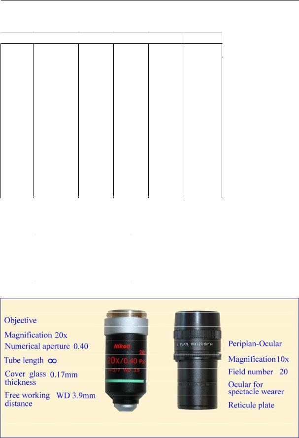
Specific properties of the objective such as magnification, numerical aperture, optical tube length, degree of aberration correction, and cover glass thickness are engraved on the outer objective barrel (Fig. 1.2-2, Table 1). Objectives designed for polarized-light microscopy consist of strain-free lens systems and are marked with the inscription P, PO, or Pol. Table 1 also gives the free working distance (FWD) between the specimen and the front lens of the objective for selected objectives of some major manufacturers.
1.2.2 Ocular (Eyepiece)
Fine structures in the intermediate image are only resolved by the human eye if they are viewed at visual angles >1'. Commonly, this requires a further magnification of the intermediate image by the ocular. The optimal resolution is achieved if the total magnification of the microscope is the numerical aperture of the objective multiplied by 500 to 1000:
M = MO * ML = 500 * N.A. 1000 * N.A.
If the total magnification lies below this range, finest structures in the intermediate image remain invisible. If it is higher, the intermediate image is magnified without any further gain in resolution (= empty magnification).
Modern oculars consist of two multi-lens components, the “eye lens” and the “field lens”, that correct optical aberrations of the ocular itself and eliminate residual aberrations of the intermediate image. A Periplan ocular, for example, contains seven lenses that are cemented into a single doublet, a single triplet, and two individual lenses. A fixed internal diaphragm is positioned in the focal plane of the ocular, between the “eye lens” and “field lens” components, in focus with the intermediate image, and defines the circular field of view.
For polarized-light microscopy, an ocular with exactly adjusted crosshairs (or a crossed micrometer disc) mounted on the fixed diaphragm not only provides the ‘N-S’ and ‘E-W’ reference directions for the vibration directions of the polarizer and analyzer, but also serves to measure angles (Ch. 2.1, 4.2.1). For measuring and counting objects in a thin section, glass discs with engraved linear and crossed micrometers or grids can be placed in the diaphragm plane. By adjusting the height of the eye lens, diaphragm and reticule are brought into focus with the intermediate image.
The specific properties of oculars are inscribed on their casing (Fig. 1.2-2, Table 1).
8
 Guide to Thin Section Microscopy Microscope
Table 1. Objectives and oculars of some renowned manufacturers
 I. Strain-free objectives for polarizing microscopy
Company |
|
Designation |
M |
|
NA |
|
|
FWD |
|
|
|
Cover glass |
||||
|
|
|
|
|
|
|
|
|
|
|
|
(mm) |
|
|
|
thickness |
Leica |
Hi Plan Pol |
4 |
0.10 |
26.2 |
- |
|||||||||||
|
Hi Plan Pol |
|
|
10 |
|
0.22 |
|
7.8 |
|
|
|
- |
||||
|
Hi Plan Pol |
|
|
20 |
|
0.40 |
|
0.9 |
|
|
|
0.17 |
||||
|
Hi Plan Pol |
|
|
40 |
|
0.65 |
|
0.31 |
|
|
|
0.17 |
||||
|
Hi Plan Pol |
|
|
63 |
|
0.75 |
|
0.31 |
|
|
|
0.17 |
||||
|
|
|
|
|
|
|
|
|
|
|
|
|
|
|
|
|
Nikon |
CFI Achromat P |
|
4 |
0.10 |
30 |
|
|
- |
||||||||
|
CFI Achromat P |
|
|
10 |
|
0.25 |
|
6.1 |
|
|
|
- |
||||
|
CFI Achromat P |
|
|
20 |
|
0.40 |
|
3 |
|
|
|
0.17 |
||||
|
CFI Achromat P |
|
|
|
40 |
|
0.65 |
|
0.65 |
|
|
|
0.17 |
|||
|
|
|
|
|
|
|
|
|
|
|
|
|
|
|
|
- |
Zeiss |
A-Plan |
|
|
|
2.5 |
|
0.06 |
|
9.4 |
|
|
|
- |
|||
|
A-Plan |
|
|
|
5 |
|
0.12 |
|
9.9 |
|
|
|
- |
|||
|
A-Plan |
|
|
|
10 |
|
0.25 |
|
4.4 |
|
|
|
- |
|||
|
A-Plan |
|
|
|
20 |
|
0.45 |
|
0.51 |
|
|
|
0.17 |
|||
|
A-Plan |
|
|
|
40 |
|
0.65 |
|
0.43 |
|
|
|
0.17 |
|||
|
|
|
|
|
|
|
|
|
|
|
|
|
|
|
|
|
Olympus |
PLN4xP |
|
|
4 |
0.10 |
18.5 |
|
|
- |
|||||||
|
ACHN10xP |
|
|
|
10 |
|
0.25 |
|
6 |
|
|
|
- |
|||
|
ACHN20xP |
|
|
|
20 |
|
0.40 |
|
3 |
|
|
|
0.17 |
|||
|
ACHN40xP |
|
|
|
40 |
|
0.65 |
|
0.45 |
|
|
|
0.17 |
|||
II. Oculars |
|
|
|
|
|
|
|
|
|
|
|
|||||
Company |
|
Designation |
|
|
|
Magnification |
Field Number |
|||||||||
|
|
|
|
|
|
|
|
|
|
|
|
|
|
|
|
(mm) |
Leica |
|
Periplan |
|
|
|
|
10 |
20 |
||||||||
|
|
Periplan crossed micrometer |
|
|
|
10 |
20 |
|||||||||
|
|
|
|
|
|
|
|
|
|
|||||||
Nikon |
|
CFI |
|
|
|
|
10 |
22 |
||||||||
|
|
CFI CM crossed micrometer |
|
|
|
10 |
22 |
|||||||||
|
|
|
|
|
|
|
|
|
|
|||||||
Zeiss |
|
W-PL, focusable |
|
|
|
|
10 |
23 |
||||||||
|
|
|
|
|
|
|
|
|
|
|||||||
Olympus |
|
WHN10x |
|
|
|
|
10 |
22 |
||||||||
|
|
WHN10x-H, focusable |
|
|
|
|
10 |
22 |
||||||||
Raith, Raase, Reinhardt – January 2011
Figure 1.2-2: Objective (Example: Nikon CFI Achromat 20x P) and ocular (Example: Leica Periplan with reticule plate)
9

Raith, Raase, Reinhardt – January 2011
Guide to Thin Section Microscopy |
Microscope |
1.2.3 Tube, objective and ocular
Objective and ocular are connected by a microscope tube. In older microscopes the tube has a specified length (Nikon, Olympus, Zeiss: 160 mm; Leitz: 170 mm) because the objectives project the real images onto a fixed plane. In modern microscopes the tube length can vary as infinity-corrected objectives are used. In such systems, the tube length is referred to as the reference focal length and ranges between 165 mm (Zeiss) and 200 mm (Leica, Nikon).
The ocular is inserted into the upper end of the tube. Two small slots at the tube edge ensure that the ocular position is fixed, with the crosshairs oriented either N-S and E-W or diagonally at 45° to these directions. To account for variable eyesight, the crosshairs can be focused by adjusting the height of the eye lens.
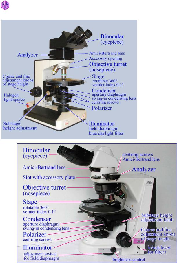
The objective is mounted at the lower end of the tube. The single-objective holders common in former petrographic microscopes are nowadays only used in reflected-light, interference and universal-stage microscopy. In modern microscopes, the objectives are mounted on a quadruple or quintuple revolving nosepiece (turret) accommodating 4 to 5 objectives of different magnification which can thus be quickly selected for observation (Fig. 1.2-3). A click-stop mechanism ensures an accurate position when changing objectives. When objectives of different magnification are used on the same object, it is desirable that the images remain focused. Thus, modern objectives have a fixed distance from the nosepiece objective mounting hole to the point of focus on the specimen (= parfocal distance; Leica, Zeiss: 45mm; Nikon: 60 mm).
1.3 Illumination
To be viewed with the microscope, the specimens, unless they fluoresce, must be illuminated. Opaque specimens (e.g. ore minerals, metals) are imaged with the proportion of light that is reflected from the specimen (reflected-light microscopy). Transparent or weakly absorbent specimens are observed using the light that passes through them (transmitted-light microscopy). The images reveal only those structures of the specimen where the colour and intensity of the transmitted light is modified through absorption, diffraction and reflection.
In older microscopes the illumination of a translucent specimen is achieved by directing the light from the sun or from a matted bulb via a planar or concave mirror and a subsequent focusing lens system (condenser) through the specimen.
In modern microscopes a built-in light source in the base of the microscope provides the specimen illumination. Commonly a 6V 20W halogen bulb is used with variable brightness control. The light emitted from the bulb is focused by a simple lens system (collector) and then directed via the condenser through the specimen (Fig. 1.4.1).
1.3.1 Aperture of illumination
A homogeneous illumination of the observed specimen area is essential for the quality of the microscopic image. Furthermore, in order to achieve optimal resolution, the cone of light rays passing through the specimen should have the largest possible opening angle (cf. Ch. 1.2.1, Aperture).
10

Raith, Raase, Reinhardt – January 2011
Guide to Thin Section Microscopy |
Microscope |
As a rule, the aperture of illumination should equate or be slightly less than the aperture of the objective. Larger apertures would cause a loss of contrast, smaller apertures a reduction of resolution. The aperture of illumination is adjusted with a diaphragm which is located below the condenser lenses (iris diaphragm or aperture diaphragm) (Fig. 1.4-1; Ch. 1.4.1). By closing the diaphragm, the illumination aperture is reduced, resulting in increased image contrast and depth of field. Opening the diaphragm increases the aperture of illumination and leads to a loss of image contrast.
1.3.2 Light field
Depending on their magnification, objectives cover specimen areas of different size (object field). To avoid blooming of the fine image details by lateral stray light, the diameter of the illuminating light bundle (light field) should not exceed the size of the viewed object field. The light field can be adjusted to the required size by a diaphragm which is located above the collector lens of the illuminator (field diaphragm) (Fig. 1.4-1; Ch. 1.4.1).
Illumination aperture and light field can also be modified by changing the focal length of the condenser. For this purpose, modern condensers are equipped with a swing-in auxiliary condensing lens which, when inserted, changes the system from long focal length (low aperture, large light field) to short focal length (high aperture, small light field size).
To achieve complete illumination of specimens when using objectives of low magnification (e.g. M = 1.25), the front lens, and in some cases the entire condenser, must be removed from the substage assembly.
A number of particular condensers has been designed for application in special imaging techniques (phase contrast, interference, fluorescence and dark field microscopy).
To ensure optimum illumination and resolution of fine specimen structures, a special illumination method was introduced by A. Köhler in 1893, which is still the most widely used method of specimen illumination in transmitted-light microscopy (see Ch. 1.4).
1.3.3 Glass diffuser and filters
Built into the lamphouse of modern microscopes, a thermal filter absorbs the heat produced by the halogen lamp, and an opal glass then diffuses the emitted light, thereby improving the homogeneous illumination of the specimen.
Various filters are either housed in the base of the microscope or can be placed in a port above the field diaphram. Commonly, a blue daylight filter serves to condition the light emitted from the artificial light source to the quality of sunlight. Neutral density filters are used to attenuate the intensity of light without changing its spectral composition. Monochromatic light which is needed for special measurements, such as the determination of refractive indexes with the immersion method, is usually generated by interference filters (dichroic filters).
11
Guide to Thin Section Microscopy |
Microscope |
|
|
|
|
Raith, Raase, Reinhardt – January 2011
Figure 1.2-3: Design of polarized-light microscopes (Nikon Eclipse 50/Pol; Leica Laborlux 12 Pol)
12
Guide to Thin Section Microscopy |
Microscope |
|
|
|
|
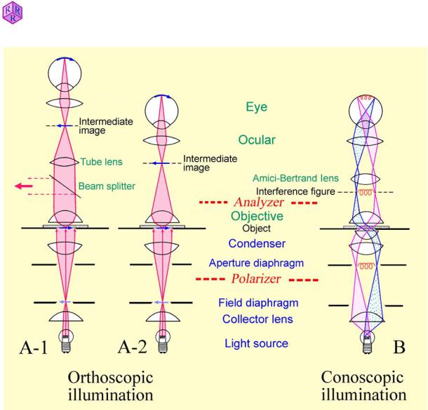
Figure 1.4-1: Orthoscopic and conoscopic ray paths in the microscope
A: Orthoscopic illumination mode. In finite tube-length microscopes, the objective produces a real inverted image (intermediate image) of the specimen which then is viewed with further enlargement through the ocular (A-2). In infinity-corrected microscopes, the objective projects the image of the specimen to infinity, and a second lens placed in the tube (tube lens) forms the intermediate image which then is viewed through the ocular (A-1). This
2011 |
imaging design allows to insert accessory components such as analyzer, compensators or |
|
|
||
January– |
beam splitters into the light path of parallel rays between the objective and the tube lens with |
|
only minor effects on the image quality. |
||
|
||
Reinhardt |
B: Conoscopic illumination mode. Parallel rays of the light cone which illuminates the |
|
specimen create an image in the upper focal plane of the objective (B). In the case of |
||
|
||
Raase, |
anisotropic crystals, an interference image is generated which can be viewed as an |
|
enlargement by inserting an auxiliary lens (Amici-Bertrand lens). The interference image can |
||
|
||
Raith, |
also be directly observed in the tube through a pinhole which replaces the ocular. |
|
|
13

Raith, Raase, Reinhardt – January 2011
Guide to Thin Section Microscopy |
Microscope |
1.4 Light paths in the microscope 1.4.1 Köhler illumination
The Köhler illumination is based on a specific geometry of light paths in the illuminating substage part of the microscope, and is achieved through a special arrangement of the light source, collector lens, field diaphragm, aperture diaphragm and condenser lens (Fig. 1.4.-1). This special illumination mode ensures an even illumination of the viewed object field (light field) and further allows to independently adjust the illumination aperture and the size of the light field.
1.The collector lens projects an enlarged image of the light source (filament of the halogen lamp) onto the front focal plane of the condenser where the aperture diaphragm resides. As a result, the illuminating light beam is leaving the condenser as a light cone consisting of bundles of parallel rays (Fig. 1.4-1). The aperture of the illuminating cone can be modified by varying the aperture of the iris diaphragm. As each point in the object field receives light rays from each point of the filament of the halogen lamp, an even illumination of the entire object field is achieved. Further images of the light source (filament) are generated in the upper focal plane of the objective (resp. the tube lens) and the upper focal plane of the ocular.
2.The condenser lens projects an image of the field diaphragm onto the specimen plane, and hence, superposed images of both object and field diaphragm are generated by the objective in the intermediate image plane where they are jointly observed through the ocular. The size of the illuminated field of the specimen (light field) can be adjusted by varying the aperture of the field diaphragm without affecting the illumination aperture (Fig. 1.4-1).
The microscope alignment for Köhler illumination is described in Chapter 1.5.
The Köhler illumination allows to examine optically anisotropic minerals in two different modes:
1.4.2 Orthoscopic mode
The divergent light rays emanating from each point of a specimen are focused in the intermediate image plane, thereby creating the real image of the specimen (Fig. 1.4-1A).
In an optically anisotropic mineral, along each direction of the illuminating cone (Ch. 4.1) light waves with different velocity (birefringence; Ch. 4.2.3) and in part also different amplitude (absorption) pass through the grain. The light waves are superposed at each point of the object image. Therefore, the image of an individual mineral grain, when viewed under strongly convergent illumination, does not provide information on the optical behaviour in different directions of the mineral.
However, when the aperture of the illumination cone is reduced by closing down the aperture diaphragm, the optical phenomena observed in the intermediate image are dominated by the properties of light waves that pass through the mineral grain at right angle to the viewing plane: orthoscopic mode (Ch. 4). It follows that direction-dependent optical properties of an anisotropic mineral in thin section must be deduced from examining several grains cut in different crystallographic orientations.
14