

Yang Fluidization, Solids Handling, and Processing
.pdfFluidized Bed Scale-up |
75 |
Di Felice et al. (1992b) evaluated the full set of scaling laws for three different Geldart powder categories (A, B, and D) in the bubbling and slugging fluidization regimes. Pressure fluctuations were used as the basis for the scaling comparisons. In the bubbling regime, the RMS and dominant frequencies of the pressure fluctuations showed good agreement for all three powder categories. Only Geldart groups B and D were considered in the slugging regime. They exhibited fair agreement in the RMS of their pressure fluctuations, but their dominant frequencies disagreed. They found that the full set of scaling laws are valid for bubbling beds fluidizing powders in Geldart groups A, B, and D. They also concluded that the full set of scaling laws is not sufficient for slugging beds where particle-particle interactions are also thought to be important.
8.3Verification of Scaling Laws for Spouting Beds
He et al. extended the scaling considerations to spouting beds. They showed that for spouting beds the full set of scaling relationships, Eq. 37, must be augmented with two new parameters, the internal friction angle and the loose packed voidage. By systematic tests in different sized cold beds as well as comparisons between hot and cold beds, they showed excellent agreement when the full set of scaling parameters augmented with the two spouting bed parameters were held constant. Close agreement was found for spout diameter, fountain height, longitudinal pressure profiles and dead zone boundary. Figure 33 shows a comparison of dimensionless spout diameter versus dimensionless height. Cases A and B differ in bed diameter by a factor of 2 but all of the dimensionless groups are maintained equal. In case C, the Reynolds numbers based on particle diameter and bed diameter are mismatched and in case D, the Froude number is mismatched. When the internal friction angle and sphericity were mismatched, there was a large disagreement in fountain height.
The internal friction angle is also important for slugging beds (Zenz and Othmer, 1960). DiFelice et al. (1992 a, b) did not report their values; it could be that the disagreement they found in their slugging bed tests was due to mismatches of the internal friction angle.

Fluidized Bed Scale-up |
77 |
hydrodynamic parameters. Three different bed materials were used in the cold bed: Olivine sand and two different size distributions of the hot-bed material, one properly scaled and one out of scale. The solid-to-gas density ratio of the sand was 17% higher than the ratio for the combustor while the scaled down hot bed material, when used in the cold bed, has a solid-to-gas density 14% lower than the ratio for the combustor. The sand also had a lower sphericity than the hot bed material. The out-of-scale hotbed material was also used to illustrate the sensitivity of the scaling to the D/dp parameter. The nondimensional form of the capacitance probe measurements agreed within 25% for the sand and the properly scaled hotbed material; the agreement was best in the upper part of the bed. The dimensionless bubble velocity disagreed by as much as 18%. The properly scaled hot-bed material showed only slightly better agreement than that for the sand, but the mismatch in the density ratio and the sphericity for the sand was small. The improperly scaled hot-bed material had a maximum deviation of 38% from the hydrodynamics of the hot-bed combustor. When the pressure or the superficial velocity of the cold bed was changed from the correct value based on the scaling parameters, the disagreement in bubble properties increased. Almstedt and Zakkay concluded that behavior which is hydrodynamically similar to that of a pressurized fluidized bed combustor can be achieved using a properly scaled cold model.
Glicksman and Farrell (1995) constructed a scale model of the Tidd 70 MWe pressurized fluidized bed combustor. The scale model was fluidized with air at atmospheric pressure and temperature. They used the simplified set of scaling relationships to construct a one-quarter length scale model of a section of the Tidd combustor shown in Fig. 34. Based on the results of Glicksman and McAndrews (1985), the bubble characteristics within a bank of horizontal tubes should be independent of wall effects at locations at least three to five bubble diameters away from the wall. Low density polyurethane beads were used to obtain a close fit with the solid-to-gas density ratio for the combustor as well as the particle sphericity and particle size distribution (Table 6).
Differential pressure measurements were made between several vertical elevations within the bed. The probability density function of the cold model and combustor gave very close agreement (Fig. 35). The solid fraction profiles were obtained from the vertical pressure profile with a hydrostatic assumption. The cold model solid fraction profile showed very close agreement with data taken from pressure taps in two different locations within the combustor (Fig. 36). The solid fraction shows a
78 Fluidization, Solids Handling, and Processing
somewhat unexpected behavior with a lower value near the distributor, possibly due to many small low velocity bubbles at that location which coalesce and increase in velocity until the tube bank is encountered. The power spectral density of the combustor exhibited several distinct peaks at increasingly higher frequencies. All but the first peak were not seen in the cold model. The peaks could be due to tube vibrations in the hot bed, fluctuations upstream or downstream of the bed or hydromechanical interactions between the bed and the internals. The long length of the pressure leads or the in-bed location of the taps could also have contributed to the peaks. Further measurements in the combustor are needed to resolve their origin.
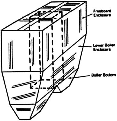
Figure 34. Tidd boiler enclosure with scaled section designated. (From Glicksman and Farrell, 1995.)

80 Fluidization, Solids Handling, and Processing
Farrell (1996) experimentally evaluated the importance of the solid-to-gas density ratio (ρS /ρf) for scaling the hydrodynamics of bubbling and slugging fluidized beds. Two bed materials, polyethylene plastic (ρs = 918 kg/m3) and a dolomite/limestone sorbent mixture (ρs = 2670 kg/m3), were used to create a mismatch in the density ratio. The size of the particles was chosen such that the remaining simplified scaling parameters were matched. Measurements showed that the internal angle of friction was similar between the two materials. A 10.2 cm diameter bed with a mock tube bundle was used to make bubbling regime comparisons, while a 5.1 cm diameter bed was used to compare the behavior of the two materials in the slugging regime. In addition, the character of the bub- bling-slugging transition was also explored.
Figure 37 compares the solid fraction profiles in the 10.2 cm bubbling bed for the two bed materials at uo /umf = 1.2. In this particular case, the solid fraction of the sorbent material is less than the plastic in the lower regions of the bed, with good agreement in the upper section of the bed. However, for the same conditions, the dimensionless standard deviation of the time-varying pressure drop showed the best agreement in the bottom of the bed with a large discrepancy in the upper portion of the bed. The bubbling-slugging transition behavior was evaluated in the 5.1 cm diameter bed. Horio et al. (1992) proposed using the inflection points in plots of the root-mean-square of the gauge pressure versus superficial velocity (uo) to identify flow regime boundaries. Figure 38 shows this behavior for the two bed materials. The plastic bed material has a much broader transition region between its fully bubbling and fully slugging regimes than the sorbent material and the nature of this transition is different between the two materials. Therefore the solid-to-gas density ratio influences both the hydrodynamics in the bubbling regime and the boundary at which the transition to slugging occurs. This is consistent with the conclusion of Glicksman et al. (1993b) where they found that it is essential to match the density ratio when scaling circulating fluidized bed hydrodynamics.
9.0APPLICATIONS OF SCALING TO COMMERCIAL BUBBLING FLUIDIZED BED UNITS
A substantial number of experimental demonstrations of the validity of scaling has increased awareness of the concept and confidence in its application. Although applications to commercial designs have been undertaken, unfortunately only a modest number have been documented in the open literature.


82 Fluidization, Solids Handling, and Processing
Scaling has many useful applications. The dynamic characteristics of different bed designs can be quickly compared. The influence of bed diameter on hydrodynamic behavior can be studied by the use of several different size models. The models allow easy experimental examination of existing operating characteristics. The beds also can be used to quickly confirm the influence of proposed modifications. Since the models usually operate at ambient conditions, it is possible to instrument them to observe detailed behavior. This allows a better understanding of the fundamental physics as well as the identification of hydrodynamic factors needed for proper correlation of performance.
The earliest scaling studies were directed at atmospheric bubbling bed combustors. To date, a rich variety of questions have been addressed. Jones and Glicksman (1986) constructed a model of the 20 MWe bubbling bed pilot plant jointly sponsored by the Tennessee Valley Authority and the Electric Power Research Institute (EPRI) at Paducah, Kentucky. Figure 39 shows a photograph of the in-bed tubes installed in the scale model. The model, which is roughly 100 by 120 cm in cross section, simulates twothirds of the entire 20 MW pilot plant. Care was taken to carefully match the pilot plant tube bundle geometry and distributor design. Steel grit particles with the same dimensionless size distribution and sphericity as the hot bed material were used. The full set of scaling parameters was matched in the model and the combustor. The largest discrepancy was in the solid-to-gas density ratio which was 18% smaller in the model than the pilot plant.
Figure 39. Model of 20 MW bubbling fluidized bed combustor showing tube arrangement. (From Jones and Glicksman, 1986.)

84 Fluidization, Solids Handling, and Processing
gas flow has a velocity much higher than the bubble rise velocity (Glicksman and Piper, 1987). This led to a mechanistic model for gas throughflow aided by the low resistance of the bubble cavity (Yule and Glicksman, 1988) and an accurate prediction of bubble volume flow rate and bed expansion (Glicksman et al. 1991b).
Commercial bubbling bed combustors must operate satisfactorily over a range of part-load conditions. While reducing the total combustion rate, it is necessary to keep bed operating temperature constant. This requires a reduction in the heat transfer to the water-filled tubes within the bed. One technique utilizes the contraction of the bed which accompanies a decrease in superficial velocity. As the bed contracts, some of the tube rows are uncovered, reducing the net heat transfer. The scale model allowed many different tube arrangements to be tested; six tube configurations were examined. Figure 41 shows three of the six different tube bank configurations which were tested. The validity of the scaling technique was confirmed by a comparison of the bed expansion measured for the pilot plant and that found in the model equipped with the same tube bank geometry (Fig. 42).
A second method to reduce load while maintaining constant bed temperature is to reduce the superficial velocity below umf to a portion of the bed. In this design, the bed does not contain vertical partitions above the distributor. The scale model was used to determine the rate of growth of the fixed bed in the defluidized zone along with the heat transfer to tubes in that region. Figure 43 shows a typical pattern of particle accumulation in a slumped zone adjacent to an actively fluidized zone. Heat transfer coefficients are also shown. Note that tubes near the upper surface of the defluidized zone, which experience a downflow of solids, have a very high heat transfer rate.
In a bubbling bed operating at high ratio of uo /umf , there is a considerable amount of solids present in the freeboard, particularly near the bed surface in the so-called “splash zone.” The high density of particles in the freeboard can cause substantial combustion and emission release in that zone as well as freeboard overheating if tubes are not present. The average density of solids was measured in the freeboard of the scale model of the 20 MW pilot plant (Glicksman and Piper, 1987). As shown in Fig. 44, the average density in the freeboard decreases exponentially with distance above the dense bed. Also shown on the figure is the predicted behavior based on a bubble eruption model (Glicksman and Yule, 1991).