

10.Control units
.pdfChapter 10 − Control Units |
Page 1 of 5 |
|
Table of Content |
|
|
Table of Content ........................................................................................................................................................... |
1 |
|
10 |
Control Units..................................................................................................................................................... |
2 |
10.1 |
Exercises ....................................................................................................................................................... |
3 |
10.2 |
Selected Answers .......................................................................................................................................... |
4 |
Index ............................................................................................................................................................................. |
|
5 |
Principles of Digital Logic Design |
Enoch Hwang |
Last updated 3/18/2003 7:54 PM |
Chapter 10 − Control Units |
Page 2 of 5 |
10 Control Units |
|
|
|
|
|
|
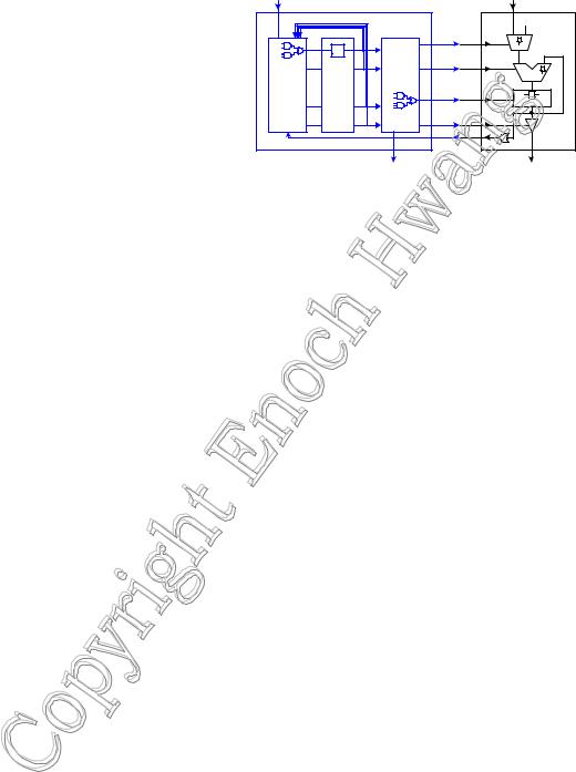
Chapter 9 described how a datapath is designed |
Control |
|
|
Data |
||
and how it is used to execute a particular algorithm by |
|
|
||||
Inputs |
|
|
Inputs |
|||
specifying the control words to manipulate the |
|
|
|
|
|
'0' Datapath |
datapath at each clock cycle. In that chapter, we tested |
|
|
Control unit |
|
|
|
the datapath by setting the control word signals |
|
|
|
1 |
0 |
|
|
ff |
|
s |
|
y |
|
manually. However, to actually have the datapath |
|
|
|
|
|
|
|
State |
Output |
|
|
|
|
automatically operate according to the control words, a |
Next- |
|
|
ALU |
||
Memory |
Logic |
Control |
|
|||
state |
|
|
||||
control unit circuit is needed that will generate these |
Logic |
register |
|
Signals |
|
ff |
control signals automatically at each clock cycle. |
|
|
|
|
|
register |
|
|
|
|
|
|
|
The control unit is a sequential circuit in which |
|
|
|
Status |
|
|
its outputs are dependent on both its current and past |
|
|
|
|
|
|
|
|
|
Signals |
|
|
|
inputs. This history of past inputs is stored in the state |
|
|
Control |
|
|
Data |
memory and is said to represent the state of the |
|
|
Outputs |
|
Outputs |
|
|
|
|
|
|
|
|
circuit. Thus, the circuit changes from one state to the next when the content of the memory changes. Depending on |
||||||
the current state of the circuit and the input signals, the next-state logic will determine what the next state ought to |
||||||
be by changing the content of the state memory. Hence, a sequential circuit executes by going through a sequence of |
||||||
states. Since the state memory is finite, therefore the total number of different states that the circuit can go to is also |
||||||
finite. This is not to be confused with the fact that the sequence length can be infinitely long. However, because of |
||||||
the reason of having only a finite number of states, a sequential circuit is also referred to as a finite-state machine |
||||||
(FSM). |
|
|
|
|
|
|
The control unit inside the microprocessor is thus an example of a finite-state machine. By stepping through a sequence of states, the control unit controls the operations of the datapath. For each state that the control unit is in, the output logic that is inside the control unit will generate all the appropriate control signals for the datapath to perform one operation.
The speed in which the finite-state machine sequences through the states is determined by the clock signal. At each active edge of the clock signal, the state memory register is enabled and the next state value is stored in. The limiting factor for the clock speed is whether all the operational units inside the datapath can finish their operations within one clock period.
In this chapter, we will look at the design of finite-state machines in general. In the next chapter, we will combine what we have learned about datapaths and finite-state machines together to construct a complete microprocessor.
Finite-state machines are classified into two main types: Moore and Mealy. A Moore type FSM is one where the output of the machine is dependent only on the current state, whereas a Mealy type FSM is one where the output is dependent on both the current state and the input signals.
Principles of Digital Logic Design |
Enoch Hwang |
Last updated 3/18/2003 7:54 PM |
Chapter 10 − Control Units |
Page 3 of 5 |
10.1 Exercises
Principles of Digital Logic Design |
Enoch Hwang |
Last updated 3/18/2003 7:54 PM |
Chapter 10 − Control Units |
Page 4 of 5 |
10.2 Selected Answers
Principles of Digital Logic Design |
Enoch Hwang |
Last updated 3/18/2003 7:54 PM |
Chapter 10 − Control Units
Index
C
Control unit, 2
F
Finite-state machine, 2
FSM. See Finite-state machine.
M
Mealy FSM, 2
Microprocessor control unit, 2 next-state logic, 2 output logic, 2
Page 5 of 5
state memory, 2 Moore FSM, 2
N
Next-state logic, 2
O
Output logic, 2
S
Sequential circuit, 2
State, 2
State memory, 2
Principles of Digital Logic Design |
Enoch Hwang |
Last updated 3/18/2003 7:54 PM |