

enhwm13e
.pdfEthernut Version 1.3
Hardware User`s Manual
Manual Revision: 1.8
Issue date: November 2005
Copyright 2001-2005 by egnite Software GmbH. All rights reserved.
egnite makes no warranty for the use of its products and assumes no responsibility for any errors which may appear in this document nor does it make a commitment to update the information contained herein.
egnite products are not intended for use in medical, life saving or life sustaining applications.
egnite retains the right to make changes to these specifications at any time, without notice.
All product names referenced herein are trademarks of their respective companies. Ethernut is a registered trademark of egnite Software GmbH.
Contents
About the Ethernut 1.3 Board . . . . . . . . . . . . . . . . . . . . . . . . . . . . . . . . . . . . . . .1 Ethernut Features . . . . . . . . . . . . . . . . . . . . . . . . . . . . . . . . . . . . . . . . . . . . . . .1 Block Diagram . . . . . . . . . . . . . . . . . . . . . . . . . . . . . . . . . . . . . . . . . . . . . . . . .2 LED Indicators . . . . . . . . . . . . . . . . . . . . . . . . . . . . . . . . . . . . . . . . . . . . . . . . .3 Serial Ports . . . . . . . . . . . . . . . . . . . . . . . . . . . . . . . . . . . . . . . . . . . . . . . . . . . .3 Ethernet Port . . . . . . . . . . . . . . . . . . . . . . . . . . . . . . . . . . . . . . . . . . . . . . . . . . .3 Expansion Port . . . . . . . . . . . . . . . . . . . . . . . . . . . . . . . . . . . . . . . . . . . . . . . . .3 Power Supply . . . . . . . . . . . . . . . . . . . . . . . . . . . . . . . . . . . . . . . . . . . . . . . . . .4 Watchdog Timer . . . . . . . . . . . . . . . . . . . . . . . . . . . . . . . . . . . . . . . . . . . . . . . .4 System Clock . . . . . . . . . . . . . . . . . . . . . . . . . . . . . . . . . . . . . . . . . . . . . . . . . .4 Flash ROM . . . . . . . . . . . . . . . . . . . . . . . . . . . . . . . . . . . . . . . . . . . . . . . . . . . .4 Static RAM . . . . . . . . . . . . . . . . . . . . . . . . . . . . . . . . . . . . . . . . . . . . . . . . . . . .5 EEPROM . . . . . . . . . . . . . . . . . . . . . . . . . . . . . . . . . . . . . . . . . . . . . . . . . . . . . .5 Configuration Jumpers . . . . . . . . . . . . . . . . . . . . . . . . . . . . . . . . . . . . . . . . . .5 Upgrading from Previous Ethernut Revisions . . . . . . . . . . . . . . . . . . . . . . .5
Quick Start . . . . . . . . . . . . . . . . . . . . . . . . . . . . . . . . . . . . . . . . . . . . . . . . . . . . . . .6
Prerequisites for Operation . . . . . . . . . . . . . . . . . . . . . . . . . . . . . . . . . . . . . . .6
Precautions . . . . . . . . . . . . . . . . . . . . . . . . . . . . . . . . . . . . . . . . . . . . . . . . . . . .6
Board Installation . . . . . . . . . . . . . . . . . . . . . . . . . . . . . . . . . . . . . . . . . . . . . . .7
Testing the Board . . . . . . . . . . . . . . . . . . . . . . . . . . . . . . . . . . . . . . . . . . . . . . . . .9 Ethernet Controller Read/Write Loop . . . . . . . . . . . . . . . . . . . . . . . . . . . . . .10 Jump to Bootloader . . . . . . . . . . . . . . . . . . . . . . . . . . . . . . . . . . . . . . . . . . . .10 SRAM Read/Write Loop . . . . . . . . . . . . . . . . . . . . . . . . . . . . . . . . . . . . . . . . .10 Send Broadcasts Loop . . . . . . . . . . . . . . . . . . . . . . . . . . . . . . . . . . . . . . . . . .10 Exit BaseMon . . . . . . . . . . . . . . . . . . . . . . . . . . . . . . . . . . . . . . . . . . . . . . . . .10
Network Configuration . . . . . . . . . . . . . . . . . . . . . . . . . . . . . . . . . . . . . . . . . . . .11
DHCP/BOOTP Method . . . . . . . . . . . . . . . . . . . . . . . . . . . . . . . . . . . . . . . . . .12
Fixed IP Address . . . . . . . . . . . . . . . . . . . . . . . . . . . . . . . . . . . . . . . . . . . . . .12
ARP Method . . . . . . . . . . . . . . . . . . . . . . . . . . . . . . . . . . . . . . . . . . . . . . . . . .12
Testing Network Operation . . . . . . . . . . . . . . . . . . . . . . . . . . . . . . . . . . . . . .13
Jumper Configuration . . . . . . . . . . . . . . . . . . . . . . . . . . . . . . . . . . . . . . . . . . . .14
Jumper Overview . . . . . . . . . . . . . . . . . . . . . . . . . . . . . . . . . . . . . . . . . . . . . .14
Hardware Expansion . . . . . . . . . . . . . . . . . . . . . . . . . . . . . . . . . . . . . . . . . . . . . .15
Expansion Port . . . . . . . . . . . . . . . . . . . . . . . . . . . . . . . . . . . . . . . . . . . . . . . .15
Analog Input Port . . . . . . . . . . . . . . . . . . . . . . . . . . . . . . . . . . . . . . . . . . . . . .16
Troubleshooting . . . . . . . . . . . . . . . . . . . . . . . . . . . . . . . . . . . . . . . . . . . . . . . . .17
Sick Ethernuts . . . . . . . . . . . . . . . . . . . . . . . . . . . . . . . . . . . . . . . . . . . . . . . . . . .20
Schematic . . . . . . . . . . . . . . . . . . . . . . . . . . . . . . . . . . . . . . . . . . . . . . . . . . . . . .21
About the Ethernut 1.3 Board
About the Ethernut 1.3 Board
Low-cost Ethernet capability can be added to many embedded applications.
Since its introduction in the year 2000, Ethernut boards have been used to develop some of the most innovative products. Using the hardware, firmware, software and tools, developers have everything they need to develop leading networked devices rapidly and affordably. The board is well suited for application development in a wide range of applications. Some areas are:
Networked sensors
Remote monitoring equipment
Alarm service providing
Remote diagnose and service
Industrial Ethernet applications
Home and building control
Ethernut Features
Ethernut 1.3 is a small (78 x 98 mm) board combining Atmel's ATmega128 RISC microcontroller with Realtek’s RTL8019AS Ethernet controller. The main features are:
ATmega 128 RISC microcontroller with up to 16 MIPS throughput
Full duplex IEEE 802.3 compliant 10 Mbps Ethernet controller with on-board RJ-45 connector
Two serial ports, one RS-232 at DB-9 connector
128 kByte in-system programmable Flash ROM
4 kByte in-system programmable EEPROM
32 kByte external SRAM
22 programmable digital I/O lines
8-channel, 10-bit analog/digital converter
Two 8-bit and two 16-bit timers/counters
Watchdog timer for enhanced reliability
LED indicators for power supply and Ethernet activity
Single power supply DC 9-12V
1
Ethernut Hardware Manual
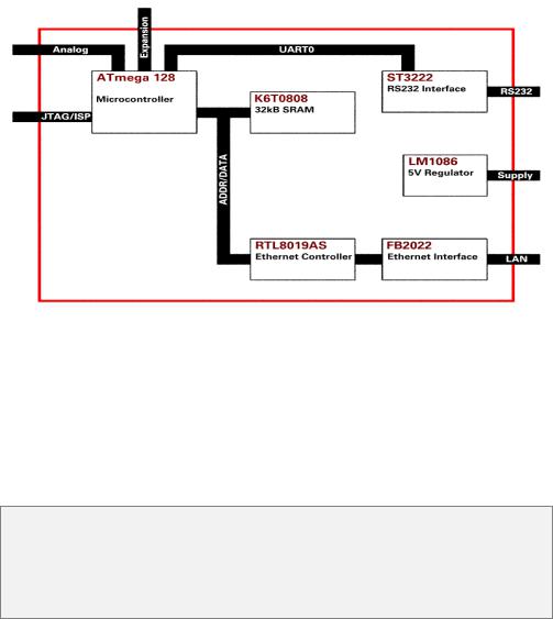
Block Diagram
The block diagram shows the main components.
Definitely the most important part is the ATmega 128 microcontroller. It’s a quite complex chip and described in detail in Atmel’s ATmega 128 data sheet. Almost all pins are routed to the Ethernut expansion port, a 64-pin connector, which can be used to add custom hardware like the Medianut MP3 decoder with LCD interface.
The microcontroller provides two UART channels, one is routed to the on-board RS-232 level shifters.
While Ethernut’s software offers serveral bootloader capabilities over RS-232 or Ethernet, program code is initially uploaded through the JTAG or SPI interface. The connector layouts conform to Atmel’s 10-pin JTAG interface. Unfortunately the same type of connector is used by Atmel for the SPI interface.
WARNING: Never plug an SPI programming adapter in to the Ethernut 1.3 JTAG connector or a JTAG adapter into the SPI connector. This will result in a power supply shortcut and will at least blow the fuse of your power supply.
2
About the Ethernut 1.3 Board
LED Indicators
The Ethernut 1.3 board is equipped with four LEDs, two red colored, a green and a yellow LED.
The first red LED1 is directly connected to the power supply. It is lit when power is applied to the board.
The second red LED2 is connected to the UART0 transmit line and is lit when serial data is transmitted.
A green and a yellow LED (LED3 and LED4 resp.) are used to indicate activity on the Ethernet port. The yellow LED indicates the network link status and is lit when the link status is OK. The green LED indicates receive and transmit activity from and to the network.
Serial Ports
Ethernut provides an on-board DB-9 connector for RS-232 serial communication. IC6 is used to convert the required voltage levels for RS-232 from the 5V power supply.
The second serial interface, UART1, is available on the expansion port at TTL level.
Ethernet Port
Ethernut provides an on-board modular RJ-45 connector for its twisted pair Ethernet port. This port is connected to the RTL8019AS Ethernet controller via a 10Base-T transformer/filter. The interface supports the maximum cable length of 100 meters between the Ethernet board and a hub.
Expansion Port
Add-on boards can be added to the expansion port. These boards may contain simple I/O circuits driven by the Ethernut board, or may be equipped with their own processor, using the Ethernut board as an Ethernet I/O processor only.
3

Ethernut Hardware Manual
Power Supply
The complete logic of the Ethernut board is driven by a 5V regulator, IC8. An unregulated power supply of DC 9-12V with a minimum current of 200 mA is sufficient to run the board.
Four different methods may be used to connect an external power supply.
1A standard 2.1 mm barrel connector. This input is protected by a rectifier bridge (D1, D2, D3 and D4).
2Using pins 4, 5 and pins 7, 8 of the Ethernet twisted pair connector. In this case pins 1 and 3 and pins 2 and 4 of jumper JP3 must be shortened. Like the barrel connector, this input is protected by a rectifyer bridge. A special power supply injector is required for the Ethernet cable. Do not set jumpers on JP3 without such an injector. You may destroy other equipment attached to the Ethernet cable.
3Pin 9 of the RS232 DB-9 connector can be used to supply the Ethernut board or draw power from it. To use this option, a 0 Ohm resistor R35 must be mounted on the back side of the board.
4The DC signal is routed to the Ethernut expansion connector to either supply add-on boards or to receive power supply from an add-on board.
As soon as power is attached to any of the inputs mentioned above, the red LED1 will lit.
Watchdog Timer
Software bugs, temporary hardware failures caused by electrical transients or interference and many other problems might cause the system to malfunction. The ATmega128 microcontroller (IC1) provides an on-chip watchdog timer, which forces a system reset, if the application program fails to periodically update this timer.
System Clock
The ATmega 128 microcontroller clock is generated by a 14.7456 MHz crystal (Y1), which may be replaced by a crystal of up to 16 MHz. An additional 32.768 kHz crystal (Y2) drives an on-chip asynchronous timer, which is typically used for a software realtime clock. The Ethernet controller is driven by a separate 20-MHz crystal (Y3).
WARNING: Note, that changing any crystal will alter the Ethernut board's EMC characteristics and require re-testing.
Flash ROM
The ATmega 128 provides 128 kBytes of on-chip, non-volatile flash memory space, which is used for program code and read-only data storage. This memory is organized as 64K x 16 bits and can be (re-)programmed through in-system programming.
4
About the Ethernut 1.3 Board
Static RAM
The Ethernut board provides 32 kByte SRAM (IC4), which is used as read/write data storage. The lower 4352 bytes of this external memory chip are overlayed by the internal ATmega128 register and SRAM space. The required address latch is provided by IC3.
EEPROM
The ATmega 128 provides 4 kBytes of on-chip, non-volatile, electrically erasable memory, typically used for configuration data storage. This memory provides read/write access under program control as well as through in-system programming. Note, that EEPROM write access is much slower (about 2.5 ms) than writing to SRAM.
Configuration Jumpers
The board is equipped with 2 jumper areas.
JP1 and JP2 configure the connection to the serial device (UART0).
JP3 enables power supply over Ethernet cable.
Upgrading from Previous Ethernut Revisions
Ethernut has undergone many changes since its initial release in the year 2000, but board dimensions and positions of main connectors remained unchanged.
Also, the software still supports all previous Ethernut Boards including revision 1.1 with the ATmega 103 microcontroller, which is no longer in production. However, there are a few things to consider.
The most important change to notice is the second programming connector for JTAG programming. Always plug the correct adapter cable into the specified connector.
Since board revision G, Ethernut 1.3 emulates an EEPROM for the Ethernet Controller. Upgrading from previous revisions of Ethernut 1 requires to link the application code with the latest Nut/OS libraries. Otherwise remove R7 (top) and stuff R37 (bottom) for full compatibility with previous revisions.
5
Ethernut Hardware Manual
Quick Start
This chapter will help you quickly set up and start using the Ethernut board.
Prerequisites for Operation
The following items are necessary to run the Ethernut board:
A standard PC equipped with Linux or Windows, an available serial COM port and a twisted pair Ethernet adapter card.
Terminal emulation software, such as TeraTerm or Hyperterminal.
An unregulated power supply matching your local mains. It should supply DC 9-12V, 200 mA minimum, on a standard 2.1 mm barrel connector.
Two straight-through twisted pair cables together with a hub or switch or a twisted pair cross cable, if you don't got a hub or switch.
The following items are included in the Ethernut Starter Kit:
Ethernut Board.
SP Duo JTAG and SPI compatible programming adapter.
A straight through serial communication cable with a DB-9 female on one end and a DB-9 male connector on the other.
A CD with all required software tools and documents. Additionally check www.ethernut.de for the latest releases.
This manual.
It is further assumed, that you got some basic knowledge about digital hardware and TCP/IP networking. This manual will not present any of these basics, but you can find excellent books or web resources about these topics.
Precautions
Born out of an Open Source Project, the Ethernut board is a commercial product, from which you expect some kind of fail safe operation. But also keep in mind, that a bare electronic circuit is a fragile product, which demands careful handling. In the first place learn how to avoid problems caused by electrostatic discharge.
Moreover, no limitations are applied to chip programming, which may guard you against accidents. In particular, the ATmega 128 microcontroller may be completely disabled by misprogramming its fuses. Thus we strictly recommend not to change the fuse settings, if you are not absolutely sure what you are doing.
The following fuses had been enabled (programmed to zero) before shipping the board: JTAGEN, SPIEN, EESAVE, BOOTSZ1, BODLEVEL, BODEN and CKOPT. All other fuses remain unprogrammed (erased to one).
6