7.2 MULTI-ACCESS PROCEDURES — ANTICOLLISION |
219 |
((X − 1) − 0) of their serial numbers. The transponders are informed of the number of subsequent bits by an additional parameter (NVB = number of valid bits) in the REQUEST command.
Let us now illustrate in more detail the sequence of a dynamic binary search algorithm on the basis of the example in Figure 7.25. We use the same transponder serial numbers as in the previous example. Since we are applying the rule (Table 7.6) unchanged, the sequence of individual iterations corresponds with that of the previous example. In contrast, however, the amount of data to be transferred — and thus the total time needed — can be reduced by up to 50%.
RFID Handbook: Fundamentals and Applications in Contactless Smart Cards and Identification, Second Edition
Klaus Finkenzeller Copyright 2003 John Wiley & Sons, Ltd.
ISBN: 0-470-84402-7
8
Data Security
RFID systems are increasingly being used in high security applications, such as access systems and systems for making payments or issuing tickets. However, the use of RFID systems in these applications necessitates the use of security measures to protect against attempted attacks, in which people try to trick the RFID system in order to gain unauthorised access to buildings or avail themselves of services (tickets) without paying. This is nothing new — we only have to look to myths and fairy stories to find examples of attempts to outsmart security systems. For example, Ali Baba was able to gain access to the supposedly secure hideout of the 40 thieves by discovering the secret password.
Modern authentication protocols also work by checking knowledge of a secret (i.e. a cryptographic key). However, suitable algorithms can be employed to prevent the secret key being cracked. High security RFID systems must have a defence against the following individual attacks:
•Unauthorised reading of a data carrier in order to duplicate and/or modify data.
•The placing of a foreign data carrier within the interrogation zone of a reader with the intention of gaining unauthorised access to a building or receiving services without payment.
•Eavesdropping into radio communications and replaying the data, in order to imitate a genuine data carrier (‘replay and fraud’).
When selecting a suitable RFID system, consideration should be given to cryptological functions. Applications that do not require a security function (e.g. industrial automation, tool recognition) would be made unnecessarily expensive by the incorporation of cryptological procedures. On the other hand, in high security applications (e.g. ticketing, payment systems) the omission of cryptological procedures can be a very expensive oversight if manipulated transponders are used to gain access to services without authorisation.
8.1Mutual Symmetrical Authentication
Mutual authentication between reader and transponder is based upon the principle of three-pass mutual authentication in accordance with ISO 9798-2, in which both

participants in the communication check the other party’s knowledge of a secret (secret cryptological key).
In this procedure, all the transponders and receivers that form part of an application are in possession of the same secret cryptological key K (→ symmetrical procedure). When a transponder first enters the interrogation zone of a reader it cannot be assumed that the two participants in the communication belong to the same application. From the point of view of the reader, there is a need to protect the application from manipulation using falsified data. Likewise, on the part of the transponder there is a need to protect the stored data from unauthorised reading or overwriting.
The mutual authentication procedure begins with the reader sending a GET CHALLENGE command to the transponder. A random number RA is then generated in the transponder and sent back to the reader (response → challenge–response procedure). The reader now generates a random number RB. Using the common secret key K and a common key algorithm ek, the reader calculates an encrypted data block (token 1), which contains both random numbers and additional control data, and sends this data block to the transponder.
Token 1 = eK(RB||RA||IDA||Text1)
The received token 1 is decrypted in the transponder and the random number RA contained in the plain text is compared to the previously transmitted RA. If the two figures correspond, then the transponder has confirmed that the two common keys correspond. Another random number RA2 is generated in the transponder and this is used to calculate an encrypted data block (token 2), which also contains RB and control data. Token 2 is sent from the transponder to the reader.
Token 2 = eK(RA2||RB||Text2)
The reader decrypts token 2 and checks whether RB, which was sent previously, corresponds with RB, which has just been received. If the two figures correspond, then the reader is satisfied that the common key has been proven. Transponder and reader have thus ascertained that they belong to the same system and further communication between the two parties is thus legitimised (Figure 8.1).
To sum up, the mutual authentication procedure has the following advantages:
•The secret keys are never transmitted over the airwaves, only encrypted random numbers are transmitted.
|
|
|
|
GET_CHALLENGE |
|
|
|
|
|
|
|
|
|
|
|
|
|
|
|
|
|
Random A |
|
|
|
|
Reader |
|
|
|
Transponder |
|
Token 1 |
|
|
|
|
|
|
|
|
|
|
|
|
|
|
|
|
|
|
|
|
|
|
Token 2 |
|
|
|
|
|
|
|
|
|
|
|
|
|
|
|
|
|
|
|
|
|
|
|
Key K |
|
|
|
|
|
Key K |
|
Figure 8.1 Mutual authentication procedure between transponder and reader
8.2 AUTHENTICATION USING DERIVED KEYS |
223 |
•Two random numbers are always encrypted simultaneously. This rules out the possibility of performing an inverse transformation using RA to obtain token 1, with the aim of calculating the secret key.
•The token can be encrypted using any algorithm.
•The strict use of random numbers from two independent sources (transponder, reader) means that recording an authentication sequence for playback at a later date (replay attack) would fail.
•A random key (session key) can be calculated from the random numbers generated, in order to cryptologically secure the subsequent data transmission.
8.2Authentication Using Derived Keys
One disadvantage of the authentication procedure described in Section 8.1 is that all transponders belonging to an application are secured using an identical cryptological key K . For applications that involve vast quantities of transponders (e.g. the ticketing system for the public transport network, which uses several million transponders) this represents a potential source of danger. Because such transponders are accessible to everyone in uncontrolled numbers, the small probability that the key for a transponder will be discovered must be taken into account. If this occurred, the procedure described above would be totally open to manipulation.
A significant improvement on the authentication procedure described can be achieved by securing each transponder with a different cryptological key. To achieve this, the serial number of each transponder is read out during its production. A key KX is calculated (→ derived) using a cryptological algorithm and a master key KM, and the transponder is thus initialised. Each transponder thus receives a key linked to its own ID number and the master key KM.
The mutual authentication begins by the reader requesting the ID number of the transponder (Figure 8.2). In a special security module in the reader, the SAM (security authentication module), the transponder’s specific key is calculated using the master key KM, so that this can be used to initiate the authentication procedure. The SAM
|
|
GET_ID |
|
Production |
|
Reader |
ID-Number |
time |
|
|
|
|
ID-Number |
|
|
|
|
GET_CHALLENGE |
|
|
|
Key KM |
Random A |
Transponder |
KM |
|
|
Token 1 |
|
|
|
Key KX |
Token 2 |
Key KX |
|
|
|
|
Figure 8.2 In an authentication procedure based upon derived keys, a key unique to the transponder is first calculated in the reader from the serial number (ID number) of the transponder. This key must then be used for authentication

normally takes the form of a smart card with contacts incorporating a cryptoprocessor, which means that the stored master key can never be read.
8.3Encrypted Data Transfer
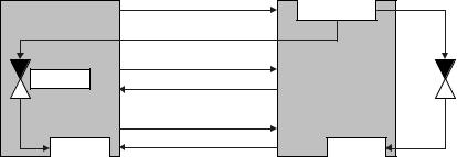
Chapter 7 described methods of dealing with interference caused by physical effects during data transmission. Let us now extend this model to a potential attacker. We can differentiate between two basic types of attack. Attacker 1 behaves passively and tries to eavesdrop into the transmission to discover confidential information for wrongful purposes. Attacker 2, on the other hand, behaves actively to manipulate the transmitted data and alter it to his benefit. See Figure 8.3.
Cryptological procedures are used to protect against both passive and active attacks. To achieve this, the transmitted data (plain text) can be altered (encrypted) prior to transmission so that a potential attacker can no longer draw conclusions about the actual content of the message (plain text).
Encrypted data transmission always takes place according to the same pattern. The transmission data (plain text) is transformed into cipher data (cipher text) (→ encryption, ciphering) using a secret key K and a secret algorithm. Without knowing the encryption algorithm and the secret key K a potential attacker is unable to interpret the recorded data. It is not possible to recreate the transmission data from the cipher data.
The cipher data is transformed back to its original form in the receiver using the secret key K and the secret algorithm (→ decryption, deciphering). See Figure 8.4.
If the keys K for ciphering and K for deciphering are identical (K = K ) or in a direct relationship to each other, the procedure is a symmetrical key procedure. If knowledge of the key K is irrelevant to the deciphering process, the procedure is an asymmetrical key procedure. RFID systems have for a long time used only symmetrical procedures, therefore we will not describe other procedures in further detail here.
If each character is individually encrypted prior to transmission, the procedure is known as sequential ciphering (or stream ciphering). If, on the other hand, several characters are incorporated into a block then we talk of a block cipher. Because block
|
|
|
|
|
|
|
|
|
|
Interference |
|
|
|
Transmission data |
|
|
|
|
|
|
Received data |
|
|
|
|
|
|
|
|
|
|
|
|
|
|
|
|
|
|
|
|
|
|
|
|
|
|
|
|
|
|
|
94 |
0E |
5F |
85 |
FF |
32 |
|
|
|
|
|
|
94 |
1E |
5F |
85 |
FF |
32 |
|
|
|
|
|
|
|
|
|
|
|
|
|
|
|
|
|
|
|
|
|
|
|
|
|
|
|
|
|
|
|
|
|
|
|
|
|
|
|
|
|
|
|
|
|
|
|
|
|
|
|
|
|
|
|
|
|
|
|
|
|
|
|
|
|
|
|
|
|
|
|
|
Attacker 1 |
|
|
|
Attacker 2 |
|
|
|
|
|
|
1E |
|
|
|
|
|
|
|
|
|
|
|
|
|
|
|
|
|
|
|
|
|
|
|
|
|
|
|
|
|
|
|
|
|
|
|
|
|
|
|
|
|
|
|
|
|
|
|
|
|
|
|
|
|
|
|
|
|
|
|
|
|
|
|
|
|
|
|
|
|
|
|
|
|
|
|
|
|
|
|
|
|
|
|
|
|
|
|
|
|
|
|
|
|
|
|
|
|
|
|
|
|
|
|
|
|
|
|
|
|
|
|
|
|
|
|
|
|
|
|
|
|
|
|
|
|
|
|
|
|
|
|
|
|
|
|
|
|
|
|
|
|
|
|
|
|
|
|
|
|
|
|
|
|
|
|
|
|
|
|
|
|
|
|
|
|
|
|
|
|
|
Figure 8.3 Attempted attacks on a data transmission. Attacker 1 attempts to eavesdrop, whereas attacker 2 maliciously alters the data
8.3 ENCRYPTED DATA TRANSFER |
225 |
Transmission data
94  0E 5F 85 FF
  32
32 
Key K
K |
K ′ |
Received data |
|
|
|
94 0E 5F 85 FF 32 |
|
Cipher data |
|
|
38 F0 17 33 05 62 |
|
???
Attacker
Figure 8.4 By encrypting the data to be transmitted, this data can be effectively protected from eavesdropping or modification
ciphers are generally very calculation intensive, they play a less important role in RFID systems. Therefore the emphasis is placed on sequential ciphers in what follows.
A fundamental problem of all cryptological procedures is the secure distribution of the secret key K , which must be known by the authorised communication participants prior to the start of the data transfer procedure.
8.3.1Stream cipher
Sequential ciphers or stream ciphers are encryption algorithms in which the sequence of plain text characters is encrypted sequentially using a different function for every step (Fumy, 1994). The ideal realisation of a stream cipher is the so-called one-time pad, also known as the Vernam cipher after its discoverer (Longo, 1993).
In this procedure a random key K is generated, for example using dice, prior to the transmission of encrypted data, and this key is made available to both parties (Figure 8.5). The key sequence is linked with the plain text sequence by the addition of characters or using XOR gating. The random sequence used as a key must be at least as long as the message to be encrypted, because periodic repetitions of a typically short key in relation to the plain text would permit cryptoanalysis and thus an attack on the transmission. Furthermore, the key may only be used once, which means that an extremely high level of security is required for the secure distribution of keys. Stream ciphering in this form is completely impractical for RFID systems.
To overcome the problem of key generation and distribution, systems have been created based upon the principle of the one-time pad stream cipher, that use a socalled pseudorandom sequence instead of an actual random sequence. Pseudorandom sequences are generated using so-called pseudorandom generators.
Figure 8.6 shows the fundamental principle of a sequential cipher using a pseudorandom generator: because the encryption function of a sequential cipher can change (at random) with every character, the function must be dependent not only upon the
|
|
Transmitted data |
|
|
|
Received data |
|
.... |
1 |
0 |
1 |
1 |
1 |
0 .... |
.... |
1 |
0 |
1 |
1 |
1 |
0 .... |
|
|
|
|
|
|
|
Cipher |
|
|
|
|
|
|
|
|
|
|
|
|
|
text |
|
|
|
|
|
|
.... |
0 |
0 |
1 |
0 |
1 |
0 .... |
.... |
0 |
0 |
1 |
0 |
1 |
0 .... |
|
|
|
Key |
|
|
|
|
|
Key |
|
|
Key destruction
Key generation
Figure 8.5 In the one-time pad, keys generated from random numbers (dice) are used only once and then destroyed (wastepaper basket). The problem here is the secure transmission of the key between sender and recipient
M
Pseudorandom generator
 g(K)
g(K)
 f(K)
f(K)
1 0 1 1 0 1
Transmission data
Figure 8.6 The principle underlying the generation of a secure key by a pseudorandom generator
current input character but also upon an additional feature, the internal state M . This internal state M is changed after every encryption step by the state transformation function g(K ). The pseudorandom generator is made up of the components M and g(K ). The security of the cipher depends principally upon the number of internal states M and the complexity of the transformation function g(K ). The study of sequential ciphers is thus primarily concerned with the analysis of pseudorandom generators.
The encryption function f (K ) itself, on the other hand, is generally very simple and can only comprise an addition or XOR logic gating (Fumy, 1994; Glogau, 1994).
From a circuitry point of view, pseudorandom generators are realised by state machines. These consist of binary storage cells, so-called flip-flops. If a state machine
8.3 ENCRYPTED DATA TRANSFER |
227 |
Shift register
 Timing pulse
Flip-flop 
Switching device (coder)
Figure 8.7 Basic circuit of a pseudorandom generator incorporating a linear feedback shift register (LFSR)
has n storage cells then it can take on 2n different internal M states. The state transformation function g(K ) is represented by combinatorial logic (a more detailed explanation of the functionality of state machines can be found in Chapter 10). The implementation and development of pseudorandom generators can be greatly simplified if we restrict ourselves to the use of linear feedback shift registers (Figure 8.7).
A shift register is realised by the serial connection of flip-flops (outputn is connected with inputn+1) and the parallel connection of all timing inputs. The content of the flipflop cell is shifted forwards by one position with every timing pulse. The content of the last flip-flop is output (Golomb, 1982; Rueppel, 1986).
RFID Handbook: Fundamentals and Applications in Contactless Smart Cards and Identification, Second Edition
Klaus Finkenzeller Copyright 2003 John Wiley & Sons, Ltd.
ISBN: 0-470-84402-7
9
Standardisation
The development of standards is the responsibility of the technical committee of the ISO. The ISO is the worldwide union of national standardisation institutions, such as DIN (Germany) and ANSI (USA).
The description of standards in this chapter merely serves to aid our technical understanding of the RFID applications dealt with in this book and no attempt has been made to describe the standards mentioned in their entirety. Furthermore, standards are updated from time to time and are thus subject to change. When working with the RFID applications in question the reader should not rely on the parameters specified in this chapter. We recommend that copies of the original versions in question are procured. The necessary addresses are listed in Section 14.2 at the end of this book.
9.1Animal Identification
ISO standards 11784, 11785 and 14223 deal with the identification of animals using RFID systems.
•ISO 11784: ‘Radio-frequency identification of animals — Code structure’
•ISO 11785: ‘Radio-frequency identification of animals — Technical concept’
•ISO 14223: ‘Radio-frequency identification of animals — Advanced transponders’: Part 1: Air interface
Part 2: Code and command structure Part 3: Applications
The constructional form of the transponder used is not specified in the standards and therefore the form can be designed to suit the animal in question. Small, sterile glass transponders that can be injected into the fatty tissues of the animal are normally used for the identification of cows, horses and sheep. Ear tags or collars are also possible.
9.1.1ISO 11784 – Code structure
The identification code for animals comprises a total of 64 bits (8 bytes). Table 9.1 shows the significance of the individual bits.

230 |
|
9 STANDARDISATION |
|
Table 9.1 Identification codes for animals |
|
|
|
Bit number |
Information |
Description |
|
|
|
1 |
Animal (1)/non-animal |
Specifies whether the transponder is used for |
|
application (0) |
animal identification or for other purposes |
2–15 |
Reserved |
Reserved for future applications |
16 |
Data block (1) follows/no data |
Specifies whether additional data will be |
|
block (0) |
transmitted after the identification code |
17–26 |
Country code as per ISO 3166 |
Specifies the country of use (the code 999 |
|
|
describes a test transponder) |
27–64 |
National identification code |
Unique, country-specific registration number |
|
|
|
The national identification code should be managed by the individual countries. Bits 27 to 64 may also be allocated to differentiate between different animal types, breeds, regions within the country, breeders etc., but this is not specified in this standard.
9.1.2ISO 11785 – Technical concept
This standard defines the transmission method for the transponder data and the reader specifications for activating the data carrier (transponder). A central aim in the development of this standard was to facilitate the interrogation of transponders from an extremely wide range of manufacturers using a common reader. A reader for animal identification in compliance with the standard recognises and differentiates between transponders that use a full/half duplex system (load modulation) and transponders that use a sequential system.
9.1.2.1Requirements
The standard specifies the operating frequency for the reader as 134.2 kHz ± 1.8 kHz. The emitted field provides a power supply for the transponder and is therefore termed the ‘activation field’.
The activation field is periodically switched on for 50 ms at a time and then switched off for 3 ms (1 in Figure 9.1). During the 50 ms period when it is switched on it waits
50 ms |
3 |
50 ms |
3 |
100 ms |
3 |
50 ms |
20 |
50 ms |
Activation field: |
|
|
|
|
|
|
|
|
Pause: |
|
|
|
|
|
|
|
|
Full duplex transponder: |
|
|
|
|
|
|
|
|
Sequential transponder: |
|
|
|
|
|
|
|
|
|
1 |
|
|
2 |
|
|
3 |
|
Figure 9.1 Path of the activation field of a reader over time: 1 no transponder in interrogation zone, 2 full/half duplex (= load modulated) transponder in interrogation zone, 3 sequential transponder in the interrogation zone of the reader


