

S.N.A.P. protocol specification V1.00
.pdfS.N.A.P
Scaleable Node Address Protocol
Protocol version |
1.00 |
Document revision |
1.03 |
|
|
© 19982002 HTH, Document revision 1.03

S.N.A.P - Scaleable Node Address Protocol
Preface.
Thanks for your interest in the S.N.A.P network protocol. Our goal was to define a simple and generic network protocol that could be used in many different types of microcontroller applications as well for educational purposes. We are not implying that S.N.A.P will solve all network problems in this universe because it won't! There may be other protocols that suit your specific application better. Never the less we think S.N.A.P is a great protocol for it's intended use and therefore we decided to share it with the rest of the community.
Our priority has been to keep it as simple as possible and our internal mantra has been KISS (Keep It Simple Stupid). It's harder than one can imagine balancing technical advanced functions with simplicity and we have had many ideas that we scraped due to the reason that it would increase the learning curve and make it harder to implement. The persons involved in the development of S.N.A.P all have many years background as teachers and knows how important it is to keep things simple for easy understanding. Something to remember is that you many times can build advanced functions even if you are using very simple tools!
One drawback with defining such a flexible network protocol is that it makes it almost impossible to define everything since many parameters (such as timing etc.) depends on what kind of media being used. We could have defined S.N.A.P to be used with our PLM-24 Power Line Modems only and with strict timing information but then it wouldn't be so versatile as we wanted it.
This document version specifies the S.N.A.P packet framing format. Consider S.N.A.P as an ongoing project that we will continue to work on and add more functionality to over time. We hope you find our work useful and welcome you to e-mail comments, suggestions and ideas. Due to the amount of e-mails received we are not always able to reply to you personally but we do read all e-mails.
Note that the purpose of this S.N.A.P documentation is not to be a complete book with answers on every question that may arise (we may eventually do something like that in the future). However, we have done our best in given time to provide enough information to get you started and the best way to learn how S.N.A.P works in reality is to start experiment with it and study the source code examples that is available on our web-site.
In short, if you find S.N.A.P useful then feel free to use it and all we ask is that you give credit where credit is due and if S.N.A.P doesn't suit your specific needs then you should consider using another network protocol.
Good luck with your projects!
Copyright © 1998-2002 HTH |
Document revision 1.03 |
- 1 -

S.N.A.P - Scaleable Node Address Protocol
1.0 Introduction.
Why yet another protocol? Because we at HTH needed a protocol for our PLM-24 based home automation system. After studying several other protocols available we decided to sit down and define a generic protocol that gave us the flexibility we was looking for. We wanted a protocol that could easily be implemented in small microcontrollers with very limited computing and memory resources. We also wanted to be able to use the same protocol in larger systems. The solution was to make the protocol scaleable.
S.N.A.P allows for different packet length and different protocol complexity. It can be used as a very simple protocol without any flags or error detection, or the programmer can use up to 24 flags and any of the defined error detection methods, depending on the current need (or personal skill). Since S.N.A.P is scaleable, both simple (read as cheap) and sophisticated nodes can communicate with each other in the network.
That is what makes S.N.A.P unique!
Features.
-Easy to learn, use and implement.
-Free and open network protocol.
-Free development tools available.
-Scaleable binary protocol with small overhead.
-Requires minimal MCU resources to implement.
-Up to 16.7 million node addresses.
-Up to 24 protocol specific flags.
-Optional ACK/NAK request.
-Optional command mode.
-8 different error detecting methods (Checksum, CRC, FEC etc.).
-Can be used in master/slave and/or peer-to-peer.
-Supports broadcast messages.
-Media independent (power line, RF, TP, IR etc.).
-Works with simplex, half-, fullduplex links.
-Header is scaleable from 3-12 bytes.
-User specified number of preamble bytes (0-n).
-Works with synchronous and asynchronous communication.
-Works with our free PLM-24 < > TCP/IP Gateway software.
Copyright © 1998-2002 HTH |
Document revision 1.03 |
- 2 -

S.N.A.P - Scaleable Node Address Protocol
1. 1 What can S.N.A.P be used for?
We developed S.N.A.P primarily for use in home automation and control systems but it is a generic protocol and not limited to this. S.N.A.P can be used in any type of applications where an easy to learn and flexible network protocol is needed.
1.2 How small MCU'scan be used?
S.N.A.P can be implemented in almost any MCU available today. Our first S.N.A.P testprogram ran on a BASIC Stamp I from Parallax Inc. It sent 1 Byte data and used 16-bit CRC as error detection method. This tiny microcontroller has only 14 Bytes of available RAM. As another node in the network we used a standard Pentium II PC and the nodes were communicating over the mains using PLM-24 Power Line Modems.
1.3 Is S.N.A.P easy to learn?
As mentioned before it can be scaled down and used as a very simple protocol and is therefore easy to learn. This also means it's great for educational purposes and for electronic hobbyists. And many of the professionals appreciate it, since it's easy to implement and a very flexible protocol.
1.4 Using S.N.A.P in commercial applications.
S.N.A.P is free for private and commercial (requires a vendor ID#) use. All that we ask in return is that you give credit where credit is due and that you enclose the latest version of this original PDF-file (or a link to our web-site) with your applications/products.
If you intend to use S.N.A.P in any commercial application you must request a vendor ID#. This
will not cost anything. For details on how to request your own vendor ID# see our web-site at...
http://www.hth.com/snap/
1.5 Support.
S.N.A.P is released "AS IS" and we are not able to provide any free support.
1.6 Future development of S.N.A.P.
We reserve us the right to change, modify or enhance the S.N.A.P network protocol without any prior notice. Our intention is to enhance S.N.A.P with more features in the future. To stay up-to-date with the development of S.N.A.P feel free to join our mailing list, details at the end of this document. We welcome any feedback and suggestions from users. We are aware about some missing information such as collision detection an recommended time-out values. This will be included in a future revision of this document.
Copyright © 1998-2002 HTH |
Document revision 1.03 |
- 3 -
S.N.A.P - Scaleable Node Address Protocol
2.0 Protocol description.
Below is the structure of S.N.A.P described. Before we begin a few words of explanation. All communication between network nodes, is in the form of packets. These packets can be of different length. The total packet length will depend on how many address bytes (0-6 Bytes) you decide to use, how many flags bytes (0-3 Bytes), how much data you want to send (0-512 Bytes) and what error detection method you use. All of this is defined in the header definition bytes (HDB2 and
HDB1).
Each packet could be preceded with optional preamble bytes (0-n). The packet starts with a unique byte (010101002). This byte is called the synchronization byte. Any type of preamble characters can be used as long as they are not the same as the synchronization byte.
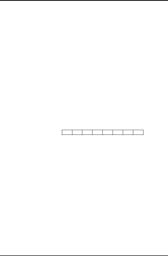
In the example below you see a small S.N.A.P packet with the following structure.
SYNC Synchronization byte
HDB2 Header Definition Byte 2
HDB1 Header Definition Byte 1
DAB1 Destination Address Byte
SAB1 Source Address Byte
DB1 Data Byte 1
CRC2 High byte of CRC-16
CRC1 Low byte of CRC-16
n bytes preamble SYNC HDB2 HDB1 DAB1 SAB1 DB1 CRC2 CRC1
The total length of this packet would be 8 Bytes (excluding the optional preamble bytes). All bytes within a group are positioned with the least significant byte to the right.
2.1 Synchronization byte - SYNC.
This byte is pre-defined to 010101002 and indicates the start of each packet.
Bit |
7 |
6 |
5 |
4 |
3 |
2 |
1 |
0 |
|
0 |
1 |
0 |
1 |
0 |
1 |
0 |
0 |
|
|
|
|
|
|
|
|
|
Copyright © 1998-2002 HTH |
Document revision 1.03 |
- 4 -
S.N.A.P - Scaleable Node Address Protocol
2.2 Overview of header definition bytes (HDB2 and HDB1).
The first two bytes after the synchronization byte are called header definition bytes, they are used to define the structure of the complete packet. The name on the fields are chosen to be easy to remember.
|
|
|
HDB2 |
|
|
|
|
HDB1 |
||
Bit 7 6 |
5 |
4 3 2 |
1 0 |
Bit 7 |
6 5 |
4 3 2 1 0 |
||||
|
|
|
|
|
|
|
|
|
||
|
D D |
S S |
P P |
A A |
|
C |
E E E |
N N N N |
||
|
|
|
|
|
|
|
|
|
|
|
|
D |
S |
|
P |
A |
|
C |
E |
|
N |
|
A |
A |
|
F |
C |
|
M |
D |
|
D |
|
B |
B |
|
B |
K |
|
D |
M |
|
B |
DAB = Number of Destination Address Bytes
SAB = Number of Source Address Bytes
PFB = Number of Protocol specific Flag Bytes
ACK = ACK/NAK bits
CMD = CoMmanD mode bit
EDM = Error Detection Method
NDB = Number of Data Bytes
2.3 Header Definition Byte 2 - HDB2.
Bit |
7 |
6 |
5 |
4 |
3 |
2 |
1 |
0 |
D D S S P P A A
Bit 7 and 6 - Destination Address Bytes (DAB)
These two bits defines number of destination address bytes in the packet. With the maximum size of 3 Bytes it gives a total of 16 777 215 different destination node addresses.
Bit 7 |
6 |
|
|
|
|
|
|
|
|
|
0 |
0 |
0 |
Byte destination address |
|
|
|
|
|
|
0 |
1 |
1 |
Byte destination address |
|
|
|
|
|
|
1 |
0 |
2 |
Bytes destination address |
|
|
|
|
|
|
1 |
1 |
3 |
Bytes destination address |
|
|
|
|
|
Copyright © 1998-2002 HTH |
Document revision 1.03 |
- 5 -

S.N.A.P - Scaleable Node Address Protocol
Bit 5 and 4 - Source Address Bytes (SAB)
These two bits defines the number of source address bytes in the packet. With the maximum size of 3 Bytes, it gives a total of 16 777 215 different source node addresses.
Bit 5 |
4 |
|
|
|
|
|
|
|
|
|
0 |
0 |
0 |
Byte source address |
|
|
|
|
|
|
0 |
1 |
1 |
Byte source address |
|
|
|
|
|
|
1 |
0 |
2 |
Bytes source address |
|
|
|
|
|
|
1 |
1 |
3 |
Bytes source address |
|
|
|
|
|
Bit 3 and 2 - Protocol specific Flag Bytes (PFB)
These two bits defines how many protocol specific flag bytes the packet includes, from 0-3 Bytes which give a total of 24 flags.
Bit 3 |
2 |
|
|
|
|
|
|
|
|
|
0 |
0 |
0 |
Byte flags |
|
|
|
|
|
|
0 |
1 |
1 |
Byte flags |
|
|
|
|
|
|
1 |
0 |
2 |
Bytes flags |
|
|
|
|
|
|
1 |
1 |
3 |
Bytes flags |
|
|
|
|
|
Bit 1 and 0 - ACK/NACK Bits (ACK)
These two bits defines if the sending node requests an ACK/NAK packet in return. These bits also acts as the actual ACK/NAK response sent from the receiving node.
Bit 1 |
0 |
|
|
|
|
|
|
|
0 |
0 |
No ACK request (Tx) |
|
|
|
|
|
0 |
1 |
ACK request (Tx) |
|
|
|
|
|
1 |
0 |
ACK response (Rx) |
|
|
|
|
|
1 |
1 |
NAK response (Rx) |
|
|
|
|
Copyright © 1998-2002 HTH |
Document revision 1.03 |
- 6 -

S.N.A.P - Scaleable Node Address Protocol
2.4 Header Definition Byte 1 - HDB1.
Bit |
7 |
6 |
5 |
4 |
3 |
2 |
1 |
0 |
|
C |
E |
E |
E |
N |
N |
N |
N |
|
|
|
|
|
|
|
|
|
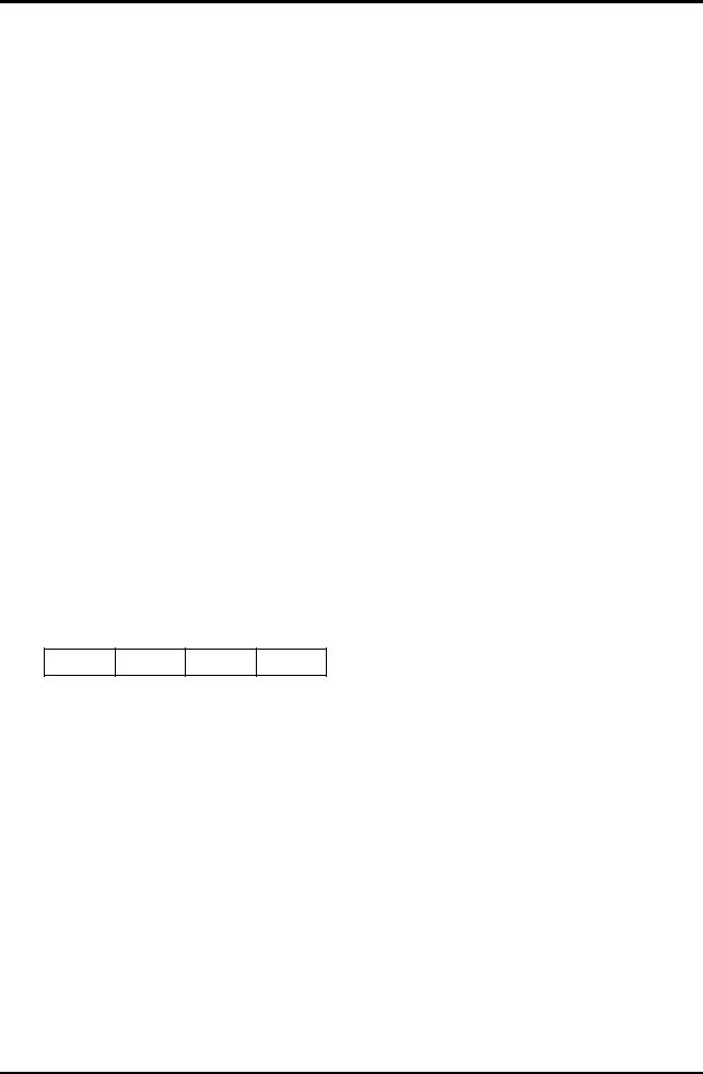
Bit 7 - Command mode bit
This bit indicates what's called command mode. This is an optional feature and if a node is not implementing it this bit should always be set to zero (CMD=0).
A node implementing this feature will be able to respond on queries from other nodes as well as send responses when for example the receiving node can't handle the packet structure in a received packet. It can be used to scan large networks for nodes and have them respond with their capabilities or for two nodes negotiating the right packet structure, among other things.
If this bit is set (CMD=1) it indicates that the data in DB1 contains a command (query or a response). This results in total 256 different commands.
The range is divided in two half's, commands between 1-127 are queries and commands between 128-255 are responses. The commands specified to date are the following. Note this is the value in DB1, not the actual CMD bit.
CMD |
Query |
CMD |
Response |
0 |
Command mode supported? |
128 |
Command mode supported |
|
|
|
|
1 |
Preferred packet structure? |
129 |
Preferred packet structure |
|
|
|
|
2 |
Reserved but not yet defined |
130 |
Reserved but not yet defined |
|
|
|
|
... |
... |
... |
... |
|
|
|
|
127 |
Reserved but not yet defined |
255 |
Reserved but not yet defined |
|
|
|
|
There are some things to think about for this to work properly. The sending node can not use an higher address range than the receiving node. This is not a problem if the receiving nodes that are implementing this feature are capable to handle all the address range (i.e. 1-16 777 215). Another solution is to assign all masters in the network (in a master/slave network) to the low address range (i.e. between 1-255).
Copyright © 1998-2002 HTH |
Document revision 1.03 |
- 7 -

S.N.A.P - Scaleable Node Address Protocol
Bit 6 to 4 - Error Detection Method (EDM)
These three bits defines what kind error detecting method is being used to validate the packet. A node does not need to support any error detection method at all (i.e. EDM = 0) or you can choose to implement a subset or all of them. For more information about this topic see section 2.6.
Bit 6 |
5 |
4 |
|
|
|
|
|
|
|
|
0 |
0 |
0 |
No error detection |
|
|
|
|
|
|
0 |
0 |
1 |
3 times re-transmission |
|
|
|
|
|
|
0 |
1 |
0 |
8-bit checksum |
|
|
|
|
|
|
0 |
1 |
1 |
8-bit CRC |
|
|
|
|
|
|
1 |
0 |
0 |
16-bit CRC |
|
|
|
|
|
|
1 |
0 |
1 |
32-bit CRC |
|
|
|
|
|
|
1 |
1 |
0 |
FEC (specific FEC standard TBD) |
|
|
|
|
|
|
1 |
1 |
1 |
User specified |
|
|
|
|
|
TBD = To Be Determined
Bit 3 to 0 - Number of Data Bytes (NDB)
These four bits defines how many bytes data there is in the packet (0-512 Bytes).
Bit 3 |
2 |
1 |
0 |
|
|
|
|
|
|
|
|
|
|
|
0 |
0 |
0 |
0 |
0 |
Byte |
|
|
|
|
|
|
|
|
0 |
0 |
0 |
1 |
1 |
Byte |
|
|
|
|
|
|
|
|
0 |
0 |
1 |
0 |
2 |
Bytes |
|
|
|
|
|
|
|
|
0 |
0 |
1 |
1 |
3 |
Bytes |
|
|
|
|
|
|
|
|
0 |
1 |
0 |
0 |
4 |
Bytes |
|
|
|
|
|
|
|
|
0 |
1 |
0 |
1 |
5 |
Bytes |
|
|
|
|
|
|
|
|
0 |
1 |
1 |
0 |
6 |
Bytes |
|
|
|
|
|
|
|
|
0 |
1 |
1 |
1 |
7 |
Bytes |
|
|
|
|
|
|
|
|
1 |
0 |
0 |
0 |
8 |
Bytes |
|
|
|
|
|
|
|
|
1 |
0 |
0 |
1 |
16 Bytes |
|
|
|
|
|
|
|
|
|
1 |
0 |
1 |
0 |
32 Bytes |
|
|
|
|
|
|
|
|
|
1 |
0 |
1 |
1 |
64 Bytes |
|
|
|
|
|
|
|
|
|
1 |
1 |
0 |
0 |
128 Bytes |
|
|
|
|
|
|
|
|
|
1 |
1 |
0 |
1 |
256 Bytes |
|
|
|
|
|
|
|
|
|
1 |
1 |
1 |
0 |
512 Bytes |
|
|
|
|
|
|
|
|
|
1 |
1 |
1 |
1 |
User specified |
|
|
|
|
|
|
|
|
Copyright © 1998-2002 HTH |
Document revision 1.03 |
- 8 -