

3. Fuselage
3.1. General
The design of the fuselage is based on payload requirements, aerodynamics, and structures. The overall dimensions of the fuselage affect the drag through several factors. Fuselages with smaller fineness ratios have less wetted area to enclose a given volume, but more wetted area when the diameter and length of the cabin are fixed. The higher Reynolds number and increased tail length generally lead to improved aerodynamics for long, thin fuselages, at the expense of structural weight.
The fuselages of all airplanes are similar in design and location. The main differences are the size and use for which the airplane is designed.
Most fuselage cross-sections are relatively circular in shape. This is done for two reasons:
1. By eliminating corners, the flow will not separate at moderate angles of attack or sideslip.
2. When the fuselage is pressurized, a circular fuselage can resist the loads with tension stresses, rather than the more severe bending loads that arise on non-circular shapes.
Many fuselages are not circular, however. Aircraft with unpressuried cabins often incorporate non-circular, even rectangular cabins in some cases, as dictated by cost constraints or volumetric efficiency.
Sometimes substantial amounts of space would be wasted with a circular fuselage when specific arrangements of passenger seats and cargo containers must be accommodated. In such cases, elliptical or double-bubble arrangements can be used. The double-bubble geometry uses intersecting circles, tied together by the fuselage floor, to achieve an efficient structure with less wasted space. The Fig. 3.1 shows a generic fuselage shape for a transport aircraft. The geometry is often divided into three parts: a tapered nose section in which the crew and various electronic components are housed, a constant section that contains the passenger cabin, and a mildly tapered tail cone.
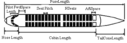
Fig. 3.1. Generic fuselage shape for a transport aircraft
Fuselages of most present-day airplanes are of all-metal construction, often of semi-monocoque design.
The trend today is to make a fuselage of fail-safe design wherein structural safety is provided by the multy-load path concept, and to achieve this for as low a weight penalty as possible.
Three main types of fuselage structures are truss, semimonocoque and monocoque.
The truss structures are formed with the spatial system of bars. Such structure is typical for old light aircraft.
A semimonocoque structure comprises a set of stressed members, namely: skin, frames or bulkheads, stringers, longitudinal beams. All mentioned members carry the part of loads. A semimonocoque structure is typical for majority of modern passenger aircraft.
In the case of monocoque fuselage, skin carries all loads, stringers, frames are absent. Such design of fuselage is rather seldom, but some units of structure may be made as a monocoque, for example aft fuselage structure, front portion of fuselage where an airborne radar is located.
3.2. Antonov -140 fuselage
The An-140 fuselage (Fig. 3.2) is a thin-wall framed shell with a cylindrical mid section and tapered double-curvature nose and tail sections. The pressurized fuselage area is bounded by frames 1 and 38. The fuselage framework made of aluminium alloys comprises stressed skin, longitudinal structural members (stringers and beams), transverse structural members (frames, bulkheads), and cabin floors.
The fuselage nose section accommodates a radome, the flight compartment with canopy, overhead emergency exit hatch, floor and bulkhead with a door. The nose gear wheel well and accessory compartments are arranged under the floor.
The radome is made of composite materials.
The canopy has a welded framework with attached electrically-heated windshields made of triplex silicate glass panels, and side windows comprising the forward and rear window panels made of organic glass. The forward left side window panel is attached to the direct vision window. Windshields are fitted with windshield wipers.
The nose portions of the fuselage shell and the flight compartment canopy are birdproof.
The flight compartment floor consists of the metal flooring panels which are hermetically sealed over the nose gear wheel bay, an access panel, and an easy-off panel provided for access to accessory compartments.
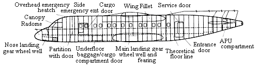
Fig. 3.2. Fuselage structural layout
The nose gear wheel well is a box covered from the outside with large and small doors made of composite materials.
The fuselage center section accommodates a passenger compartment fitted with floor and windows, a side emergency exit hatch, and a cargo door. The fuselage center section also includes the underfloor baggage/cargo compartment door and the structural center section where the wing center section and the main landing gear units attached. Outside the fuselage, the wing fillets used to accommodate equipment, and the fairing with the main landing gear wheel well are arranged.
The passenger compartment floor comprises the side panels and the easy-off panels made of composite materials, the transverse beams, side elbows, and longitudinal slotted rails.
The main landing gear wheel well is bounded on the ends by the sealed underfloor frames equipped with the landing gear unit attachment fittings, and on the top - by the sealed floor panel of the passenger compartment. From the outside of the fuselage, the well is partially covered with two doors made of composite materials and attached to the main landing gear unit struts.
The main landing gear wheel fairing comprises a shell divided into parts and reinforced with diaphragms. Arranged on the composite shell are the maintenance access doors and the equipment compartment door covers.
Wing fairings comprise the forward, side, and rear panels made of composite materials and attached to the fuselage and the diaphragms. Some of the panels are the easy-off panels, and the upper part of the side panel is deflectable downward to allow access to the systems equipment.
Provision is made in the aircraft for removal of the floor side panels in the passenger compartment, as well as of all the main gear well fairing components and the wing fillet panels together with their diaphragms to allow inspection of the fuselage and the wing center section structure.
The fuselage tail section accommodates the floor of the vestibule, lavatory and rear baggage/cargo compartment, the entrance and service doors, and the structural section for the empennage attachment (with maintenance access door), and the tip with the APU (auxiliary power unit) compartment. Outside the fuselage, the fin-to-stabilizer panel fillets are arranged. The fillets are made as composite-material skins reinforced with diaphragms.
The fuselage tip accommodates the APU compartment, the air inlet section door, the exhaust pipe fairing, and the five structural access doors. Attached to the framing are two composite-material door panels with locks.
The entrance door (stairs/door) is arranged on the fuselage port side and serves as an emergency exit. The door is equipped with built-in stairs with pivoting footsteps and handrails. The door is mounted below the floor level and opens outwards. In the closed position, the door rests with its side brackets on the door opening stops from inside the cabin with the footsteps and handrails compactly arranged in one plane on the door. The door is opened manually using either the inner or the outer handle. The door opens (is lowered) by the force of its own weight and, when close to the ground, the footsteps and handrails expand into operation position. The controls of the hydraulic system for the door closing are located on the electrical control panels inside the aircraft and on the outside, the control panels also accommodate the door closed position indication lights.
The service and cargo doors are arranged on the fuselage starboard side and serve as emergency exits. The service door is intended for the buffet/galley furnishings, and for loading baggage and cargoes into the rear baggage/cargo compartment. The cargo door is intended for loading cargoes in the mixed cargo/passenger conFig.uration version and for embarkation of a handicapped passenger in wheelchair directly into the passenger compartment. Both doors open outwards and, when closed, rest on the door opening on the inside similarly to the entrance door. The doors open manually from inside and from outside and lock open. The service door and the side emergency exit hatch each have a window, and the cargo door has two windows.
The overhead and side emergency exit hatches are supported on the inside of the fuselage by stops and locks; they open from inside the fuselage and from the outside, and are removed inside the cabin.
The service and cargo doors, and the side emergency exit hatch are blocked with special pins when the aircraft is parked, and the overhead emergency exit hatch has a lock latch. Outer handles of the entrance door and the baggage door are equipped with locks with special key inserts.
The door closed position sensors are installed in all the door and hatch openings, and the appropriate warning and caution system annunciators are provided in the flight compartment to warn about unclosed doors.