

Laboratory work № 1.3 Research of the one-tact guided and out of control rectifiers
1 Purpose of work
Research of principles of construction and functioning of the guided and out of control rectifying installations and features of their circuit technology realization.
Study of principles of construction and functioning of the guided and out of control однотактных monophase and three-phase rectifying installations. Experimental research of their basic descriptions and electromagnetic processes.
Mastering of methods of experimental determination of basic descriptions of the guided rectifiers.
2 Literature
2.1 Электропитание устройств связи: Учебник для вузов / А.А.Бокуняев, В.М. Бушуев, А.С. Жерненко, А.Ф. Кадацкий и др; Под ред. Ю.Д. Козляева. – М.: Радио и связь, 1998. – C. 69–106.
2.2 Электропитание устройств связи. Учебник для вузов / А.А.Бокуняев и др; Под ред. В.Е.Китаева. – М.: Радио и связь, 1988.– С. 87–128.
2.3 Электропитание устройств связи: Учебник для вузов / О.А. Доморацкий и др; – М.: Радио и связь, 1981. – С. 79–120.
2.4 Китаев В.Е. и др; – Электропитание устройств связи. – М.: Связь, 1975. – С. 129–160.
2.5 Иванов-Цыганов А.И. Электропреобразовательные устройства РЭС: Учебник для вузов. – М.: Высшая школа, 1991. – С. 65-143.
3 Description of laboratory model
This laboratory model (fig. 3.1) is intended for research of the guided single-phase and three-phase thyristor rectifiers of - single-phase one-tact at active (k = 1) and inductive(with the additional diode of VD1 and without him) character of loading and three-phase one-tact at active (k = 3) and inductive(with the additional diode of VD1 and without him) character of loading.
Short description of the investigated charts is driven to the table. 3.1.
A laboratory model contains:
source of G1 of three-phase sinewave tension;

Picture 3.1 - the Laboratory model
three-phase transformer of ТV1;
three-phase block of straightening of БВ, formed by the thyristors of VS1.VS3;
smoothed filter, formed by the throttle of L1;
additional diode of VD1;
resistance of loading of Rн;
quadriradiate oscillograph;
voltmeter of PV1 of tension of Ua of secondary puttee of transformer of TV1 of phase and;
ammeter of PA1 of current of Ia of secondary puttee of transformer of TV1 of phase and;
a voltmeter of PV2 of tension of Uн is in the chain of loading of rectifier;
ammeter of PA2 of current of Iн of loading;
control СУ unit by a thyristor rectifier.
A laboratory model consists of source of primary power supply of G1, transformer of ТV1, providing a concordance tension of source of primary power supply with necessary tension of loading, thyristor выпрямительного block of VS1.VS3 (or only VS1, in dependence at charts) of the smoothed filter of L1 (or without him, depending on the investigated chart), locking diode of VD1 and resistances of loading of Rн. Resistance of loading of Rн and locking diode of VD1 can become disconnected by means of switches of SW1 and SW2.
Table 3.1 is Description of the investigated charts |
|||
k |
Denotation of charts is in a model |
Description |
№ fig. |
1 |
Monophase (active loading - k = 1) |
Monophase thyristor rectifier, working on the active loading. |
3.2, and |
2 |
Monophase (inductive loading - k = 2) |
Monophase thyristor rectifier, working on the inductive loading. There is possibility of work with a locking diode (VD1). |
3.2, б |
3 |
Three-phase (active loading - k = 3) |
Three-phase thyristor rectifier, working only on the active loading. |
3.3, and |
4 |
Three-phase (inductive loading - k = 4) |
Three-phase thyristor rectifier, working on the inductive loading. There is possibility of work and with a locking diode (VD1) |
3.3, б |
A rectifier block is managed by means of chart of management СУ. A management chart produces impulses, necessary for opening of thyristors, taking into account the specific of work of the guided rectifiers. The list of model elements is presented in a table. 3.2. On the panel of operative regulations the corner of adjusting α of chart of management СУ and resistance of resistor of loading of Rн is shown out.
Virtual values of tension and current of secondary puttee of phase and transformer of ТV1 controlled accordingly by the voltmeter of PV1 and ammeter of PА1. Mean values of tension of Uн = U0 and current of Iн = I0 loading of Rн is measured accordingly by the voltmeter of PV2 and ammeter of PA2.
a) |
|
b) |
|
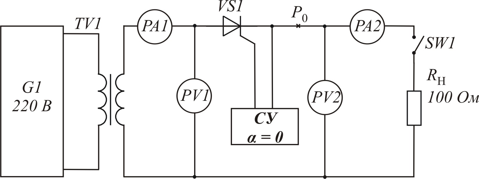

Picture 3.2 is the Monophase chart with active - k = 1 (а), inductive k = 2 (b) loading
а) |
|
b) |
|


Picture 3.3 is the Three-phase chart with active - k = 3 (а), inductive k = 4 (b) loading
Table 3.2 is Composition of laboratory model |
||||||
№ Pos. |
Type of element |
Managed parameters |
Note |
|||
parameter |
min |
max |
value |
|||
G1 |
Three-phase generator |
phase tension |
198 |
242 |
В |
Virtual value |
frequency |
50 |
400 |
Hz |
|
||
TV1 |
Three-phase transformer |
coefficient of transformation |
5 |
15 |
|
|
resistance of secondary puttee |
0,1 |
1,5 |
Ohm |
Pure resistance |
||
VS1 |
Thyristor |
|
|
|
|
|
VS2 |
Thyristor |
|
|
|
|
For the charts of k = 3 and 4 |
VS3 |
Thyristor |
|
|
|
|
For the charts of k = 3 and 4 |
VD1 |
Diode |
|
|
|
|
For the charts of k = 2 and 4 |
L1 |
Throttle |
inductance |
0,01 |
10 |
H |
For the charts of k = 2 and 4 |
Rн |
Resistor |
resistance |
5 |
200 |
Ohm |
Operative regulation |
SW1 |
Switch |
state |
Выкл. |
Вкл. |
|
Load-break |
SW2 |
Switch |
state |
Выкл. |
Вкл. |
|
Switch of blackout diode, only for charts 1, 3 |
PV1 |
Voltmeter |
|
|
|
|
Virtual value |
PV2 |
Voltmeter |
|
|
|
|
Mean value |
PA1 |
Ammeter |
|
|
|
|
Virtual value |
PA2 |
Ammeter |
|
|
|
|
Mean value |
P0 |
Control point |
|
|
|
|
|
СУ |
|
adjusting ( |
|
180 |
|
For monophase charts |
|
150 |
|
For three-phase charts |
|||
output and |
off |
on |
|
|
||
output of b |
off |
on |
|
|
||
output with |
off |
on |
|
|
||
Table 3.3 are the Investigated parameters
Denotation |
Oscillograms of electric processes |
СУ, Output and |
Tension of uya(t) on the output of control of phase а |
СУ, Output of b |
Tension of uyb(t) on the output of control of phase b |
СУ, Output with |
Tension of uyc(t) on the output of control of phase unit with |
ТV1, Ua |
Tension of ua(t) of secondary puttee of transformer of ТV1 of phase and |
ТV1, Ia |
Current of ia(t) of secondary puttee of transformer of ТV1 of phase of a |
ТV1, Ub |
Tension of ub(t) of secondary puttee of transformer of ТV1 of phase of b |
ТV1, Ib |
Current of ib(t) of secondary puttee of transformer of ТV1 of phase of b |
ТV1, Uc |
Tension of uс(t) of secondary puttee of transformer of ТV1 of phase with |
ТV1, Ic |
Current of iс(t) of secondary puttee of transformer of ТV1 of phase with |
VS1, Uка |
Tension of uVS1(t) between a cathode and anode of thyristor of VS1 |
VS1, Iа |
Current of iVS1(t) anode of thyristor of VS1 |
VS2, Uка |
Tension of uVS2(t) between a cathode and anode of thyristor of VS2 |
VS2, Iа |
Current iVS2(t) anode of thyristor of VS2 |
VS3, Uка |
Tension of uVS3(t) between a cathode and anode of thyristor of VS3 |
VS3, Iа |
Current iVS3(t) anode of thyristor of VS3 |
VD1, U |
Tension of uVD1(t) on the diode of VD1 |
VD1, I |
Current of iVD1(t) diode of VD1 |
P0, U |
Tension of u0(t) on the output of block of straightening of БВ |
P0, I |
Current of i0(t) on the output of block of straightening of БВ |
L1, U |
Tension of uL1(t) on the throttle of L1 |
L1, I |
Current of iL1(t) throttle of L1 |
Rн, U |
Tension of uн(t) on loading of Rн |
Rн, I |
Current of the iн(t) loading of Rн |
A fourchannel oscillograph, allowing to look after the form of tensions and currents in the different points of chart, enters in the set of control and measuring devices also. Synchronization of oscillograph takes place automatically in accordance with work of generator of G1. Therefore duration of involute проградуирована in the stakes of period of this generator and a screen makes 0,1.100 periods /. The list of control points of oscillograph is driven to the table. 3.3. Internal memory of oscillograph is enough for maintenance of the last period of design.