

Detlef Brumbi. "Level Measurement."
Copyright 2000 CRC Press LLC. <http://www.engnetbase.com>.

Level Measurement
Detlef Brumbi
Krohne Messtechnik GmbH
11.1 Measurements Using the Effects of Density
Displacer • Float • Pressure Gages • Balance Method
11.2 Time-of-Flight Measurements
Basic Principle • Ultrasonic • Microwaves • Laser/Light • Commonly Used Evaluation Methods
11.3 Level Measurements by Detecting Physical Properties
Electrical Properties • Radiation Attenuation • Thermal and Mechanical
11.4 Instruments
Level is defined as the filling height of a liquid or bulk material, for example, in a tank or reservoir. Generally, the position of the surface is measured relative to a reference plane, usually the tank bottom. If the product’s surface is not flat (e.g., with foam, waves, turbulences, or with coarse-grained bulk material) level usually is defined as the average height of a bounded area.
Various classic and modern methods exist to measure product level in process and storage tanks in the chemical, petrochemical, pharmaceutical, water, and food industries, in mobile tanks on vehicles and ships, but also in natural reservoirs like seas, dams, lakes, and oceans. Typical tank heights are approximately between 0.5 m and 40 m.
Two different tasks can be distinguished: (1) continuous level measurements (level indication, LI), and (2) level switches (LS) (e.g., to detect an alarm limit to prevent overfilling). Figure 11.1 shows the principal operational modes of level measurement. Every continuous system can also be used as a programmable switch. Many level devices are mounted on top of the tank and measure primarily the distance d between their mounting position and the product’s surface. The level L is then calculated, defining the tank height h as constant, as shown in Figure 11.1 and expressed as:
L = h − d |
(11.1) |
The following examples describe primarily the measurement of liquids, but most of the methods can also be applied to solids (bulk material). The emphasis of this chapter will be general information about the measurement principles. The focus of the descriptions is on the methods most commonly practiced; other principles are mentioned less comprehensively. Readers interested in more detailed discussions may refer to [1–5].
© 1999 by CRC Press LLC
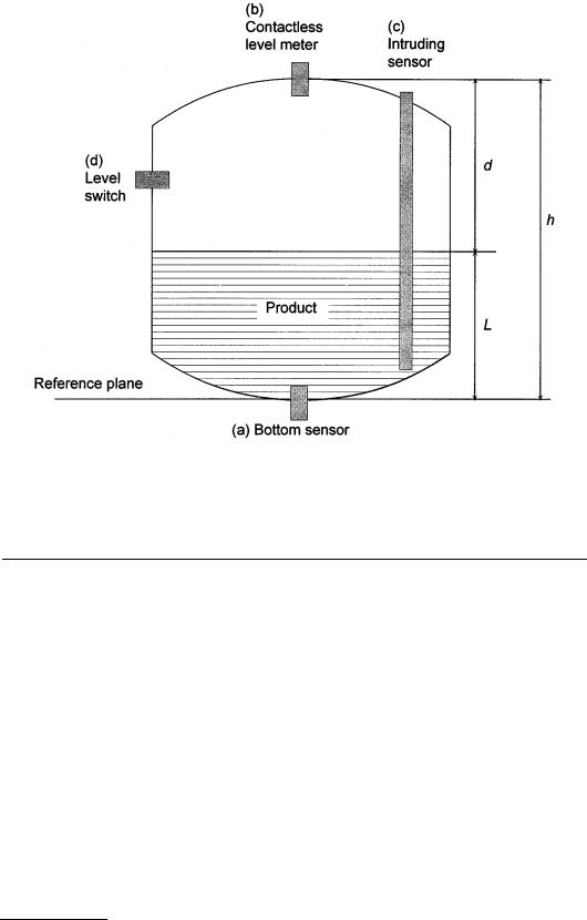
FIGURE 11.1 Representation of a tank with a liquid or solid material (hatched area), the product to be measured. The level sensor can be mounted (a) contacting product at the bottom, (b) as a contactless instrument on top, (c) as an intrusive sensor, or (d) at the sides as a level switch.
11.1 Measurements Using the Effects of Density
All methods described in this chapter have in common that the product in the tank has an effect due to its density ρ, (1) producing buoyancy to a solid submerged into the liquid, or (2) executing a force due to its weight.
Displacer
Displacers measure the buoyancy of a solid body that is partially submerged in the liquid. The change in weight is measured. Figure 11.2 illustrates the parameters used for these calculations. The cross section A of the body is assumed to be constant over its length b. The weight of force FG due to gravity g and mass m is:
FG = g m = g AbρD |
(11.2) |
The buoyant force FB accounts for the partial length Ld that is submerged with the remainder of the body in the atmosphere:
FB = g A Ld ρL + g A(b − Ld ) ρA |
(11.3) |
© 1999 by CRC Press LLC

FIGURE 11.2 Quantities of a solid body immersed into a liquid. The forces F can be calculated from Equations 2, 3, and 4. ρ = density; b = length of the body; Ld = dipped length.
Combining Equations 11.2 and 11.3 gives the resulting force to be measured by an appropriate method (see Chapter 23 of this handbook):
FR = FG − FB |
(11.4) |
The result for level Ld, related to the lower edge of the displacer is:
|
|
b(ρD |
− ρA )− |
FR |
|
|
Ld |
= |
gA |
|
(11.5) |
||
|
|
|
||||
ρL − ρA |
|
|||||
|
|
|
|
|||
The density of the body should be higher than the density of the liquid; otherwise, the measurement operating range is limited (until the displacer floats on the liquid). In another version, a servo-gage moves the displacer up and down to detect the interface between the atmosphere and a liquid, or between two different liquids, by measuring the change in buoyancy. Figure 11.3 shows a special configuration, in which a small ball with volume V is mounted to a thin wire driven by a stepping motor and put into resonant vibration. The resulting force F can be measured from the resonating frequency f of the wire between points A and B:
F = ρ |
W |
A 4 f 2 l2 |
(11.6) |
|
W |
|
where l = length of the wire between the points A and B ρw = density of the wire
Aw = cross-sectional area of the wire
© 1999 by CRC Press LLC

FIGURE 11.3 Level, interface and density sensor using the effects of buoyancy. A stepping motor drives the small ball attached to the thin wire to different heights in the liquid or to the interfaces. The resulting force F as a difference between weight force and buoyant force is measured from the resonant frequency of the wire-ball system. The lever arm excites the wire into oscillation and a sensor coil coupled to the lever arm measures its frequency. The signal converter controls the stepping motor and calculates the measured values [6].
And the surrounding density ρL can be calculated: |
|
|
|
|
|
F = g V (ρD − ρL ) ρL |
= ρD |
− |
F |
(11.7) |
|
g V |
|||||
|
|
|
|
Float
Floats are similar to displacers, but are swimming on the liquid’s surface due to the buoyancy. Hence, the density of the float must be lower than the density of the liquid. Figure 11.4(a) shows the principle
© 1999 by CRC Press LLC

FIGURE 11.4 Principle of operation for float level meters. (a) A counter weight balances the float that swims on the liquid’s surface. Its position represents the level. (b) The float contains a magnet that contacts a reed switch inside a guide tube. Using a bistable relay, this system is used as a level switch. One can also insert multiple relays into the tube to achieve different switching points for quasicontinuous operation.
of operation. The position of the float is (1) observed visually, or (2) transferred to an external display or to an angle transmitter. In general, the float is coupled to the transmitter magnetically. Figure 11.4(b) shows a level switch, using a reed relay magnetically coupled with the float. Also, a magnetostrictive linear sensor may determine the position of the float. For more information about this, refer to Chapter 6, Section 9 of this handbook.
If the float is very flat, it is called a “sensing plate”. This plate is mechanically guided, e.g., by a servo control, on the surface until uplift is detected. For solids, specially shaped perpendicular floats are helpful.
Pressure Gages
A hydrostatic pressure p, caused by the weight of the product, is present at the bottom of a tank, in addition to the atmospheric pressure p0:
p = p0 + g ρL L L = |
p − p0 |
(11.8) |
|
g ρL |
|||
|
|
Pressure gages at the bottom of the tank measure this pressure. In process tanks with varying atmospheric pressure, a differential pressure measurement is achieved by measuring the difference between the pressure at the bottom and that at the top of the tank, above the liquid. Figure 11.5(a) shows such a configuration with a differential pressure sensor. For techniques of pressure measurement, refer to Chapter 26, Section 1 of this handbook. Because measurement by hydrostatic pressure is proportional to the density, level errors result if density changes; see Equation 11.8. Primary pressure gaging is a mass measurement. Figure 11.5(b) shows a vertical arrangement with three sensors; the measurements of p1 and p2 are used to compensate for the influence of density ρL, and to calculate the level:
© 1999 by CRC Press LLC