

Surround
The surround loudspeakers in the plan are located at ±110° ±10° from front center, that is, between 100° and 120° from front center. This angle was determined from experiments into reproduction of sound images all around versus producing best envelopment of the listener. More widely spaced (further from the front) surrounds produced better rearward sound images at some expense in envelopment, while further forward surrounds produce better envelopment at the expense of rearward imaging. Also, 110° reportedly better represents the likely home listening situation where the principal listening position is close to a rear wall of the space, rather than in the middle of the space if the loudspeakers were more widely placed.
Surround loudspeakers height is often elevated to avoid control room equipment, doors, and so forth, and this is permissible for many kinds of surround presentations. In cinema usage and in many home systems, surrounds are elevated with respect to the audience. However, in certain types of presentations, such as music with a "middle of the band" perspective, the elevated surround may cause a curious tilt in the resulting sound field, so may not be as well liked. Applause reproduced with some kinds of live programming is also anomalous as it does not correspond to what is actually found in halls. Thus surround elevation is a question the answer to which depends largely on the program material being made in a particular studio destined for a particular reproduction situation.
37
Subwoofer
The subwoofer in a bass managed system carries the low-frequency content of all 5 channels, plus the 0.1 LFE channel content; this is a consideration in the placement. Among the others are:
• Placement in a corner produces the most output at low frequencies, because the floor and two walls serve as reflectors, increasing the output through "loading"; the subwoofer may be designed for this position and thus reduce the cone motion necessary to get flat response and this improves low-frequency headroom.
• Making an acoustical splice between the subwoofer and each of the channels is a factor that can be manipulated by moving the subwoofer around while measuring the response.
• The placement of the subwoofer and the listener determine how the sound will be affected by standing waves in the room; moving the subwoofer around for this effect may help smooth the response as well.
• Multiple subwoofers placed differently with respect to room boundaries can help smooth the modal response through multiple driving points and thus differing transfer functions between each of them and the listener. Where a room may produce ±12dB variations in response measured with high-frequency resolution equipment, that variation can be reduced with multiple subs,
Setting Up the Loudspeaker Locations with Two Pieces of String
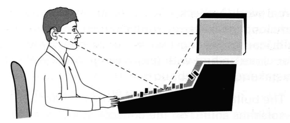
Many times a trigonometry book is not at hand, and you have to set up a surround monitor system. Here is how:
• Determine the distance from each of the left and right loudspeakers to the principal listening position to be used. Home listening is typically done at 10ft (3m), but professional listening is over a wide range due to differing requirements from a large scoring stage control room to a minimum sized booth in a location truck.
• Cut a piece of string to the length of the listening distance, or use a marked XLR extension, and make the distance between the left and right loudspeakers equal to the distance between each of them and the prime listening location. This sets up an equilateral triangle, with a 60° subtended angle between left and right loudspeakers.
• Place the center speaker on the centerline between left and right speakers. Use the full string length again to set the distance from the
38
listener to the center speaker, putting the front three loudspeakers on an arc, unless an electronic time delay compensation is available (discussed below).
• Use two strings equal in length to the listening distance. Place one from the listener to the left loudspeaker, and the other perpendicular to the first from the listener's location and to the outside of the front loudspeakers. Temporarily place a surround loudspeaker at this location, which is 90° from the left loudspeaker; 90° plus the 30° that the left is from center makes 120°. This angle is within the tolerance of the standard, but to get it right on, swing the loudspeaker along an arc towards the front by one-third of the distance between the left and center loudspeaker. This places it 110° from center front, assuming all the loudspeakers are at a constant distance from the listener.
• Repeat in a mirror image for the right surround channel (Fig. 2-5).

Fig. 2-5 The speaker layout from AES TD1001 and ITU Recommendation 775.
39
Setup Compromises
Frequently, equipment, windows, or doors are just where the loudspeakers need to be placed. Following are compromises that can be made if necessary:
• Generally, in front hearing is about three times less sensitive to errors in elevation than to horizontal errors, while at the sides and back these listening errors become much larger and therefore freedom in placement is greater. Therefore, it is permissible to elevate loudspeakers above obstructions if necessary. It is best to elevate the loudspeakers only enough to clear obstructions, since if they are too high, strong reflections of sound will occur off control surfaces at levels that have been found to be audible.
• The tolerance on surround loudspeaker placement angles is wide. Probably both surround loudspeakers should use close to the same angle from center, although the range is ±10° from the ±110° angle. Also, surround loudspeaker placement is often a compromise, because if the producer sits behind the engineer, then the surround angles for the producer are significantly less than for the engineer, especially in smaller rooms. With this in mind, it may be useful to use a somewhat wider angle from the engineer's seat than 110° to get the producer to lie within the surrounds, instead of behind them.
• With a sufficiently low crossover frequency and steep filter, along with low distortion from the subwoofer, placement of the subwoofer(s) becomes non-critical for localization. Thus, it or they may be placed where the smoothes! response is achieved. This often winds up in a front corner, or if two are used, one in a front corner and one halfway down a side wall, or centered along the two side walls, to distribute the driving points of the room and "fill in" the standing wave patterns.
Center
In many listening situations it may be impossible to place the center loudspeaker at 0° (straight ahead) and 0° elevation. There is probably other equipment that needs to be placed there in many cases. The choices, when confronted with practical situations involving displays or controls, are:
• above the display/control surfaces,
• below the display/control surfaces,
• behind the display.
Placement above the display/control surface is common in many professional facilities, but such placement can carry a penalty in many
40
instances the sound splash off the control surface is strongly above audibility. Recommended placement for monitor loudspeakers is to set them up so that the principal listener can see the whole speaker, just over the highest obstruction. This makes the sound diffract over the obstruction, with the obstruction, say a video monitor, providing an acoustic shadow so far as the sound control surface is concerned. The top of the obstruction can be covered in thin absorbing material to absorb the high frequencies that would otherwise reflect off the obstruction.
Another reason not to elevate the center speaker too much is that most professional monitor loudspeakers are built with their drivers along a vertical line, when used with the long dimension of the box vertically. This means that their most uniform coverage will be horizontal, and vertically they will be worse, due to the crossover effects between the drivers. Thus, if a speaker is highly elevated and tipped down to aim at the principal mixer's location, the producer's seat behind the mixer is not well covered—there are likely to be mid-frequency dips in the direct-field frequency response. (The producer's seat also may be up against the back wall in tight spaces, and this leads to more bass there than at the mixer's seat.)
A third reason not to elevate the studio monitor loudspeaker too much is that we listen with a different frequency response versus vertical angle. Called head-related transfer functions (HRTFs), this effect is easily observed. Playing pink noise over a monitor you are facing, tip your head up and down; you will hear a distinct response change. Since most listeners will not have highly elevated speakers, we should use similar angles as the end user in order to get a similar response.
A position below the display/control surface is not usable in most professional applications, for obvious reasons, but it may be useful in screening rooms with direct view or rear-projection monitors. The reason that this position may work is that people tend to locate themselves so they can see the screen.This makes listeners that are further away elevated compared to those closer. The problem with vertical coverage of the loudspeaker then is lessened, because the listeners tend to be in line with each other, viewed from the loudspeaker, occupying a smaller vertical angle, with consequently better frequency response.
When it is possible, the best solution may well be front projection with loudspeakers behind the screen using special perforated screens. Normally perforated motion picture theater screens have too much high-frequency sound attenuation to be useful in video applications, but in the last few years several manufacturers have brought out screens
41
with much smaller perforations that pass high-frequency sound with near transparency, and that are less visible than the standard perforations. However, perforation patterns may interact with the pixel pattern in modern projectors and produce moire patterns. For such cases, the woven and acoustically transparent screens become a necessity, such as those of Screen Research.
By the way, it is not recommended that the center loudspeaker be placed "off center" to accommodate a video monitor. Instead, change the loudspeaker elevation, raising it above the monitor, and moving it back as shown in the Fig. 2-6, creating an "acoustic shadow" so the effect of the direct reflection off the console is reduced.This is permissible since listening is more sensitive to errors in the horizontal plane than in the vertical one.
A "top and bottom" approach to the center channel to try to center a vertical phantom image on the screen may have some initial appeal, but it has two major problems. The first is that at your eardrum these two have different responses, because of the different HRTFs at the two angles. The second is that then you become supremely sensitive to seated ear height, as the change of an inch off the optimum could bring about an audible comb filter notch at high frequencies.
Left and Right
One problem that occurs when using sound accompanying a picture with the ±30° angle for left and right speakers is that they are unlikely to be placed inside the picture image area using such a wide angle. Film sound relies on speakers just inside the left and right extremities of the screen to make front stereo images that fit within the boundaries of screen. The reason for this is so that left sound images match left picture images and so forth across the front sound field. But when film is translated to video, and the loudspeakers are outside instead of inside the boundaries of the screen, some problems can arise. Professional listeners notice displacement between picture and sound images in the horizontal plane of about 4°, and 50% of the public becomes annoyed when the displacement reaches 15°. So, in instances where the picture is much smaller than 60°, there may need to be a compromise between what is best for sound (±30°), and what is best for sound plus picture (not much wider than 4° outside the limits of the picture). For those mixing program content with no picture, this is no consideration, and there are programs even with a picture where picture-sound placement is not so important as it is with many movies. Thus for a 32° total horizontal subtended angle
42
Fig. 2-6 When an associated video picture or a computer monitor are needed, the alternatives for
center are above, below, or behind the associated picture, each of which has pros and cons.

high-definition screen,3 speakers at ±30° are seen as too wide, and they would normally be brought in to be just outside the picture (or just within it if front projection and perforated screens are in use). This does limit auditory source width of direct channels and so is a compromise for sound, but is necessary for conditions where picture and sound must match localization.
Surround
Even if the surround loudspeakers are the same model as the fronts, there will still be a perceived frequency response difference. This is due to the HRTFs, the fact that the frequency response in your ear canal determines the spectrum that you hear, not the frequency response measured with a microphone. Your head has a different response for sound originating in front compared to the rear quadrant, and even when the sound fields are perfectly matched at the position of the head, they will sound different. A figure in Chapter 6 shows the frequency response difference in terms of what equalization has to be applied to the surround loudspeaker to get it to match spectrum with the center front. (This response considers only the direct sound field, and not the effects of reflections and reverberation, so practical situations may differ.)
The surrounds may be elevated compared to the fronts without causing much trouble. As they get more overhead, however, they may become less distinguishable from one another and thus more like a single monophonic channel, so too high an angle is not desirable. Experiments into surround height reveal little difference from 0° elevation to 45° elevation for most program material. Some mixers complain, however, about elevated monitors if the program contains audience sound like applause: they don't like the effect that the listeners seem located below the audience in these cases.
Subwoofer
In one case, for FCC mandated listening tests to low-bit-rate codecs for Digital Television, I first set up two subwoofers in between the left and center, and center and right loudspeakers. Since we had no means to adjust the time delay to any of the channels (discussed below), I felt that this would produce the best splice between the main channels and the subwoofer. Unfortunately, these positions of driving the room with the subwoofers, which were set up symmetrically in the room, produced lumpy frequency response. I found that by moving one of
3~^'\^'ls angle is set by noting HDTV has 1920 pixels horizontally, and that 20/20 vision corresponds to an acutance of 1/60° of arc. Dividing 1920 by 60 yields 32°.
44
the subs one-half way between the front and surround loudspeakers, the response was much smoother. This process is called "placement equalization," and although it requires a spectrum analyzer to do, it is effective in finding placements that work well.
The use of a common bass subwoofer for the 5 channels is based on psychoacoustics. In general, low-frequency sound is difficult to localize, because the long wavelengths of the sound produce little difference at the two ears. Long-wavelength sound flows freely around the head through diffraction, and little level difference between the ears is created. There is a time difference, which is perceptible, but decreasingly so at lower frequencies. This is why most systems employ five limited bandwidth speakers, and one subwoofer doing six jobs, extending the 5 channels to the lowest audible frequencies, and doing the work of the 0.1 channel.The choice of crossover frequency based on finding the most sensitive listener among a group of professionals, then finding the most sensitive program material, and then setting the frequency at two standard deviations below the mean found by experiment, resulted in the choice of 80 Hz for high-quality consumer systems.
Another factor to consider when it comes to localizing subwoofers is the steepness of the filters employed, especially the low-pass filter limiting the amount of mid-range sound that reaches the subwoofer. If this filter is not sufficiently steep, such as 24dB/octave, even if it is set to a low-frequency, higher-frequency components of the sound will come through the filter, albeit attenuated, and still permit the subwoofer to be localized. The subwoofer may also be localized in two accidental ways: through distortion components and through noise of air moving through ports. Both of these have higher-frequency components, outside the band of the subwoofer, and may localize the loudspeaker. Careful design for distortion, and locating the speaker so that port noise is directed away from direct listening path, are helpful.
No one has suggested that each of the 5 channels must be extended down to 20 Hz individually.The problem with doing this in any real room is that the low frequency response would vary dramatically from channel to channel, due to the different driving points of the room. Remember that even "full-range" professional monitors have a cutoff of 40-50 Hz, so using bass management below this frequency is still valuable. With very large PMC monitors at CES some years ago, I found the best splice to theWhise 616 subwoofer (a 5-ft cube with 4 15-in. drivers which had a low-frequency rolloff of -1 dB at 16Hz), to be at 25 Hz! And switching on and off the subwoofer for the 16-25 Hz content was audible on some of the concert hall recorded program material! But the marketplace remains practical, and the best cinema subs usually are down 1 dB at around 24-26Hz.
45
Setup variations
Use of Surround Arrays
In motion picture use, surround arrays are commonplace, having been developed over the history of surround sound from the Fantasia onwards.The AES/ITU recommendation recognizes possible advantages in the use of more than two surround loudspeakers, in producing a wider listening area and greater envelopment than available from a pair of direct radiators. The recommendation is made that if they are used, there should be an even number disposed in left and right halves in an array that occupies the region between ±60° and ±150° divided evenly and symmetrically placed. Thus if there are four surround loudspeakers, the pairs would be placed at ±60° and ±150° from center; with six speakers, the pairs would be placed at ±60°, ±105°, ±150°, etc.
However, use of this rather sparse array, with just four or six speakers depends on something vital: uncorrelated signals available for each of them. The original experiment on which the recommendation was made used four surround channels, all the way from different diffuse-field dominant microphones to the loudspeakers. I have found that an array of four surround speakers, with two driven in parallel on each side as one would do with 5.1-channel sources, is particularly poor at coloration because the comb filter fingerprint is so very audible. In small low-reverberation-time rooms for film sound mixing I prefer to use a large number of smaller loudspeakers. In one installation we have 16 surround loudspeakers, six on a side and four across the back, and this works well. These are quite small two-way designs you can hold in your hand, but the array of them sounds better, and the sound is more uniform from front to back, than any point source large surround speaker would be.
Surround arrays have some advantages and disadvantages but are commonplace in large theater spaces. Since they are used there, they also appear in dubbing stages for film, and also for television work that is done on the scale of film, such as high-end television post-production for entertainment programming. The advantages and disadvantages are:
• In large rooms, an array of loudspeakers can be designed to cover an audience area more uniformly, both in sound pressure level and in frequency response, than a pair of discrete loudspeakers in the rear corners of the auditorium.This principle may also apply to smaller control rooms, some of which use arrays.
• In addition it is possible to taper the output of the array so that the ratio of the front channel sound to surround sound stays more
46
constant from front to back of the listening area (i.e., putting more sound level into the front of the listening space than the back, in the same proportion that the front loudspeakers fall off from front to back helps uniformity of surround impression, the fall off being on the order of 4dB in well-designed theatrical installations). This is an important consideration in making the surround experience uniform throughout a listening space since it is the ratio of front to surround sound that is more important than the absolute level of each.
• In the context of sound accompanying a picture, it is harder to localize an array than discrete loudspeakers due to the large number of competing sources, thus reducing the exit sign effect. This effect is due to the fact that when our attention is drawn off the screen by a surround effect, what we are left looking at is not a continuation of the picture, but rather, the exit sign.
• A drawback is that the surround sound is colored by the strong comb filters that occur due to the multiple times of arrival of each of the loudspeakers at listener's locations.This results in a timbral signature rather like speaking in a barrel that affects the surround sound portion of the program material, but not the screen sound part. Noise-like signals take on a different timbre as they are panned from front to surround array. It turns out to be impossible to find an equalization that makes timbre constant as a sound is panned from the screen to the surrounds.
• Another drawback is that pans from the front to the surrounds seem to move from the front to the sides, and not beyond the sides to behind. Discrete rear loudspeakers or 7.1-10.2 channel systems can do this better.
The standards referred to above were written before either matixed 6.1 or discrete 6.1-channel systems separating the back from side surrounds was conceived. However, it is worth noting that in Cinerama, the surround array switch between the two available tracks between left-right surround and front-back surround. This was done manually by the theater projectionist, presumably between the segments in travelogues like This Is Cinerama. Surround arrays in cinemas today are divided into four groups: left, right, left back, and right back. The left and left back are driven together for 5.1, as are the right and right back, and the back is separated out for those mixes that have a back channel so that the array becomes left, back, right. The advantage this has is particularly in pans from screen to off screen. With conventional left-right only surround and an array the mixer will find that the sound only images from the screen to the sides of the listener; it can't go behind him.
47
Surround Loudspeaker Directivity
Depending on the program material and desires of the producer, an alternate to either a pair of discrete direct radiators, or to surround arrays, is to use special radiation pattern surround loudspeakers. A pair of dipole loudspeakers arranged in the AES/ITU configuration, but with the null of the radiation pattern pointed at the listening area, may prove useful. The idea is to enhance envelopment of the surround channel content, as opposed to the experience of imaging in the rear. These work well in the rooms for which they were designed: consumer homes without particular acoustic treatment. In lower-reverberation-time environments for their volume, such as small professional rooms, these are clearly not what is intended. Pros and cons of conventional direct radiators compared to multiradiator surrounds is as follows:
Pros for direct radiators for surround:
• rear quadrant imaging is better (side quadrant imaging is poor with both systems for reasons explained in Chapter 6);
• localization at the surround loudspeaker is easily possible if required;
• somewhat less dependence on room acoustics of the control room.
Cons for direct radiators for surround:
• too often the location of the loudspeakers is easily perceived as the source of the "surround" sound;
• pans from front to surround first snap part of the spectrum to the surround speaker, then as the pan progresses, produces strongly the sound of two separate events, then snaps to the surround; this occurs due to the different HRTFs for the two angles of the loudspeakers to the head, the different frequency response that appears in the ear canal of listeners even if the loudspeakers are matched.
Pros for multidirectional radiators for surround:
• delivers the envelopment portion of the program content (usually reverberation, spatial ambience) in a way that is more "natural" for such sound, that is, from a multiplicity of angles through reflection, not just two primary locations;
• produces more uniform balance between front channel sound and surround sound throughout a listening area; in a conventiona\ system moving off center changes the left-right surround balance much more quickly than with the dipole approach;
• makes more natural sounding pans from front to surround sound, which seem to "snap" from one to the other less than with the direct-radiator approach.
48
Cons for multidirectional radiators for surround:
• not as good at rear quadrant imaging from behind you as direct radiators;
• localization at the surround loudspeaker location is difficult (this can also be viewed as a pro, depending on point of view—should you really be able to localize a surround loudspeaker?);
• greater dependence on room acoustics of the control room, which is relied upon to be the source of useful reflections and reverberation.
There has been a great deal of hand-wringing and downright misinformation in the marketplace over the choice between direct radiator and multidirectional radiators for surround. In the end, it has to be said that both types produce both direct sound and reflected sound, so the differences have probably been exaggerated (Fig. 2-7). (Multidirectional radiators produce "direct sound" not so much by a lack of a good null in the direction of the listener as from discrete reflections.)

Fig. 2-7
Multidirectional radiators used as surrounds with the minimum output pointed at the principal listening location delivers an increased surround effect through interaction with the room acoustics of typical home listening rooms by reflecting the surround sound component of the sound field from many surfaces in the room.
Same angles as ITU, only with diffuse-field dominant dipolar radiating surrounds
Square Array
This places left and right at ±45° and surrounds at ±135°. The use of the center channel is generally minimized by these producers in their
49
work. The surround loudspeaker angle of ±110° for the AES/ITU setup was based on research that showed it to be the best trade-off between envelopment (i.e., best at ±90° when only 2 channels are available for surround) and rear quadrant imaging (which is better at ±135° than ± n0°). A square array was thoroughly studied during the quad era as a means of producing sound alf around, and information about the studies appears in Chapter 6. Nevertheless, it is true that increasing the surround angle from ±110° to ±135° improves rear phantom imaging, at the expense of envelopment.
One rationale given for the square array is the construction of four "sound fields," complete with phantom imaging capability, in each of the four quadrants front, back, left, and right. This thought does not consider the fact that human hearing is very different on the sides than in the front and back, due to the fact that our two ears are on the two sides of our heads. For instance, there is a strongly different frequency response in the ear canal for left front and left surround loudspeakers as we face forward, even if the loudspeakers are perfectly matched and the room acoustics are completely symmetrical. For best imaging all around, GuntherTheile has shown that a hexagon of symmetrically spaced loudspeakers, located at ±30°, ±90°, and ±150°, would work well. So the current 5.1-channel system may be seen as somewhat compromised in the ability to produce sound images from all around. After all is said and done, the 5.1-channel system was developed for use in accompanying a picture, where there was a premium placed on frontal sound images and surround sound envelopment, not on producing sound images all round.
Close-Field Monitoring
An idea that sounds immediately plausible is "near-field monitoring," perhaps better termed close-field monitoring. The idea is that small loudspeakers, located close to the listener, put the listener in a sound field where direct sound predominates over reflected sound and reverberation. Thus such loudspeakers and positioning are allegedly affected less by the room acoustics than are conventional loudspeakers at a greater distance, and have special qualities to offer, such as flatter response (Fig. 2-8).
Unfortunately, in real-world situations, most of the advantages of the theory of near-field listening are unavailable, sotheterm close-field monitoring is probably more apt.The loudspeakers used are small compared to the range of wavelengths being radiated, and thus broadly radiate sound. The broadly radiating sound interacts with nearby surfaces strongly. For instance, "near-field" monitors on top of a console meter
50
Fig. 2-8 So
called "near-field" monitoring suffers from the same problem as the elevated monitor, splashing excessive sound off the control surface. Moving the speaker to behind the console can be an improvement.
Near-field monitor also splashes sound off the control surface

Loudspeaker mounted behind console uses it as a barrier, though sound diffracts over this console and still reflects, it is at a lower level than when mounted on the top
bridge reflect sound strongly off the console's operating surface, at levels well above audibility. Also, the console surfaces act to extend the baffle face of the monitor loudspeaker placed on top of the meter bridge, and this changes the mid-bass response. At mid-bass frequencies, the idea that the near-field monitor gets us out of trouble from interaction with the room is wrong. There is still just one transfer function (frequency response) associated with one source location (the loudspeaker) and one receiver location (the listener's head). The effects of standing waves occur at the speed of sound, which produces effects quickly in small rooms, so the theory that we are out of trouble because the speaker is close to the listener is wrong.
Another difficulty is with the crossover region between woofer and tweeter. When used at close spacing to the listener, the exact listening position can become highly critical in many designs, as the crossover strongly affects the output of the loudspeaker spatially. Only a 6 in. move on the part of the listener located a few feet away can make a dramatic shift in the monitor's direct sound frequency response, and be audible.
The close-field monitor arose as a replacement for the simple, cheap loudspeakers, usually located on top of the console that provided
51
a "real-world" check on the large and professional built-in control room loudspeakers. In multichannel monitoring, the same theories could lead to having two systems, one huge and powerful, and the other close up and with lesser range and level capacity. This would be a mistake:
• The built-in type of control room monitors are often too high, which splashes sound off the console at levels above audibility.
• Close-field monitors suffer from the problems discussed above. They may not play loudly enough to operate at reference levels.
The best system is probably one somewhere in between the two extremes, that can play loudly enough without audible distortion to achieve reference level calibration and adequate headroom to handle the headroom on the source medium, with smooth and wide frequency range response, and otherwise meets the requirements shown inTable 2-2.
Time Adjustment of the Loudspeaker Feeds
Some high-end home controllers provide a function that is very useful when loudspeakers cannot be set up perfectly. They have adjustable time controls for each of the channels so that, for example, if the center loudspeaker has to be in line with the left and right ones for mounting reasons, then the center can be delayed by a small amount to place the loudspeaker effectively at the same distance from the listener as left and right, despite being physically closer.
The main advantage of getting the timing matched among the channels has to do with the phantom images that lie between the channels. If you pan a sound precisely halfway between left and center, and if the center loudspeaker is closer to you than the left one, you will hear the sound closer to the center than in the chosen panned position midway between left and center. The stereo sound field seems to flatten out around the center; that is, as the sound is just panned off left towards center, it will snap rather quickly to center then stay there as the pan continues through center until it is panned nearly to the right extreme, when it will snap to the right loudspeaker. The reason for this is the precedence effect. The earlier arriving center sound has precedence over the later left and right loudspeakers.This may be one reason that some music producers have problems with the center channel. Setting the timing correctly solves this problem.
Sound travels 1128 ft/s at room temperature and sea level. If the center is 1 ft closer to you than left and right, the center time will be 1.1 ms early. Some controllers allow you to delay center in 1 ms steps, and
52
1 ms is sufficiently close to 1.1 ms to be effective. A similar circumstance occurs with the surround loudspeakers, which are often farther away than the fronts, in many practical situations. Although less critical than for imaging across the front, setting delay on the fronts to match up to the surrounds, and applying the same principle to the subwoofer, can be useful.
The amounts of such delay are much smaller typically than the amounts necessary to have an effect on lip sync for dialog, for which errors of 20ms are visible for the most sensitive listener/viewers. Note, however, that video pictures are often delayed through signal processing of the video, without a corresponding delay applied to the audio. It is best if audio-video timing can be kept to within 20ms. Note that motion pictures are deliberately printed so that the sound is emitted by the screen speakers one frame (42ms) early, and the sound is actually in sync 47 ft from the screen, a typical viewing distance.
Low-Frequency Enhancement—The 0.1 Channel
The 0.1 or LFE channel is completely different from any other sound channel that has ever existed before. It provides for more low-frequency headroom than on traditional media, just at those frequencies where the ear is less sensitive to absolute level, but more sensitive to changes in level.The production and monitoring problems associated with this channel potentially include the end user not hearing some low-frequency content at all, up through giving him so much bass that his subwoofers blow up.
With adoption by film, television, and digital video media already, the 0.1 channel has come into prominence over the past few years. With music-only formats, how will it affect them? Just what is the "0.1" channel? How do we get just part of a channel? Where did it come from, and where is it going? And most importantly of all, how does a professional apply the standards that have been established to their application, from film through television to music and games?
Film Roots
The beginnings of the idea came up in 1977 from the requirements of Gary Kurtz, producer of a then little-known film called Star Wars. At the time, it seemed likely that there would be inadequate low-frequency headroom in the three front channels in theaters to produce the amount of bass that seemed right for a war in outer space (waged in a vacuum!). A problem grew out of the fact that by the middle 1970s, multichannel film production used only three front channels—left, center, and
53
right (two "extra" loudspeaker channels called left extra and right extra, in between left and center, and center and right, were used in the 1950s Todd AO and Cinerama formats). The loudspeakers employed in most theaters were various models of Altec-Lansing Voice of the Theater. A problem with these loudspeakers was that although they use horn-loaded operation across much of the woofer's operating range for high efficiency, and thus high-level capability, below about 80 Hz the small size of the short horn became ineffective, and the speaker reverted to "bass reflex" operation with lower efficiency. In addition, the stiff-suspension, short-excursion drivers could not produce much level at lowerfrequencies, and the "wing walls" surrounding the loudspeakers that supported the bass had often been removed in theaters. For this combination of reasons, both low frequency response and headroom were quite limited.
loan Alien and Steve Katz of Dolby Labs knew that many older theaters were still equipped with five-front channels, left over from the original 70mm format. So, their idea was to put the "unused" channels back into service just to carry added low-frequency content, something that would help distinguish the 70 mm theater experience from the more ordinary one expected of a 35 mm release at the time. Gary Kurtz asked for a reel of Capricorn! to be prepared in several formats and played at the Academy theater. The format using left extra and right extra loudspeakers for added low-frequency level capability won. Thus was invented the "Baby Boom" channel, as it was affectionately named, born of necessity. Just 6 months after Star Wars, Close Encounters of the Third Kind was the first picture to use dedicated subwoofers, installed just for the purpose of playing the Baby Boom channel.
Headroom on the Medium
Another idea emerged along with that of using more speakers for low frequencies. The headroom of the magnetic oxide stripe on the 70mm film used in 1977 was the same as it was before 1960 because the last striping plant that remained was still putting on the same oxide! Since the headroom on the print was limited to 1960s performance by the old oxide, it was easy to turn down the level recorded on the film by WdB, and turn the gain back up in the cinema processor by 10dB, thus improving low-frequency headroom on the film in the boom channel, although also suffering from a greater susceptibility to hum, but that could be looked after. At first, a 250 Hz low-pass filter stripped off the higher frequencies, so hiss was no problem. Within a few films, the frequency of the low-pass filter on the boom channel was lowered to 125 Hz. This was done so that if speech was applied to the boom channel, it would not get thick-sounding, because the usual boom channel content was just the sum of the other channels low-pass filtered. Even for Star Wars, special
54
content for the boom channel was being recorded that did not appear in the main channels, so a whole new expressive range was exercised for high-level low-frequency sounds. In fact at Lucasfilm about 1982 Ben Burtt asked me for a "boom sting" button, a button that when pressed just upped the gain temporarily by 6dB—faster than using a fader.
The idea of having more low-frequency than mid-range head room proved to be a propitious one. Modern day psychoacoustics tells us that human listeners need more low-frequency sound pressure level to sound equally as loud as a given mid-range level.This is known from the equal loud-ness contours of hearing, often called the Fletcher-Munson curves, but modernized and published as ISO 226:2003. (The 1930s Fletcher-Munson curves show the equal loudness curve corresponding to 100dB sound pressure level at 1 kHz to be nearly flat in the bass, but all later experimenters find you need more bass to keep up with the loudness of the mid-range.) Observing these curves demonstrates the need for more low-frequency level capability than mid-range capability, so that a system will sound as though it overloads at the same perceived level versus frequency (Fig. 2-9).

Fig. 2-9 Equal loudness contours of hearing, sound pressure level in dB re 20[ilM/m2 (OdB SPL is about the threshold of hearing) versus frequency in Hz, from ISO 226. These curves show that at no level is the sensation of loudness flat with frequency;
more energy is required in the bass to sound equally as loud as the mid-range.
By the way, I found out about this in a completely practical way. Jabba the Hutt's voice in Jed'i started out with a talker with a very deep voice (a then-marketing guy from Dolby, Scott Schumann) recorded on a directional microphone used up close, thus boosting the bass through the proximity effect.
55
Then the voice was processed by having its frequency lowered by a pitch shifter, and a sub-harmonic synthesizer was used to provide frequencies at one-half the speech fundamental, adding content between 25 and 50 Hz corresponding to the frequencies in the speech between 50 and WOHz. All of these techniques produce ever greater levels of low bass. When I looked at the finished optical sound track of a Jabba conversation, I found that he used up virtually 100% of the available area of the track. Yet Jabba's voice is not particularly loud. Thus, really low bass program content can "eat up" the available headroom of a system quickly. This lesson surely is known to engineers who mix for CDs.
Digital Film Sound Enters the Picture
When digital sound on film came along as the first digital multichannel format, laid out in 1987 and commercially important by 1993, the 0.1 channel was added to the other five in order to have a low-frequency channel capable of greater headroom than the main channels, following the theory developed for 70mm film. Note that the five main channels have full frequency range capability extending downwards into the infrasonic region on the medium, whether film, DVD, DigitalTelevision, or any other, so the 0.1 channel provides an added headroom capability, and does not detract from the possibility of "stereo bass."
I proposed the name "5.1" in a Society of Motion Picture andTelevision Engineers (SMPTE) meeting of a short-lived subcommittee called Digital Sound on Film in October 1987. The question as to the number of channels was going around the room, and answers were heard from four through eight. When I said 5.1, they all looked at me as though I were crazy. What I was getting at was that this added channel worth of information, with great benefits for low-frequency headroom, only took up a narrow fraction of one of the main channels. In fact, the amount is really only 1/200th of a channel, because the sample rate can be made 1/200th of the main channel's sample rate (240Hz sampling, and 120HZ bandwidth for a 48kHz sampled system), but the number 5.005 just didn't quite roll off the tongue the way 5.1 did. Call the name "marketplace rounding error," if you will.
Bass Management or Redirection
In theater practice, routing of the signals from the source medium into the loudspeakers is simple. The main loudspeaker channels are "full range" and, thus, each of the five main channels on the medium is routed to the respective loudspeakers, and the 0.1 channel is routed to one or more subwoofers.This seemed like such an elegant system,
56
but it did have a flaw. When I played Laser Discs at home, made from film masters, I noticed that my wide-range home stereo system went lower in the bass than the main channel systems we used in dubbing. So what constitutes a "full-range" channel? Is it essentially flat to 40 Hz and rolled off steeply below there like modern direct-radiator, vented-box main channel theater systems installed in large, flat baffle walls? Or is it the 25 Hz range or below of the best home systems?This was disturbing, because my home system revealed rumbles that were inaudible, or barely audible when you knew where they were, on the dubbing stage system, even though it had the most bass extension of any such professional system.
During this time, I decided to use a technique from satellite-subwoofer home systems, and sum the lowest bass (below 40 Hz) from the five main channels and send it to the subwoofer, along with the 0.1-channel content,Thus, the subwoofer could do double duty, extending the main channels downwards infrequency, as well as adding the extra 0.1 -channel content with high potential headroom. All this so the re-recording mixers could hear all of the bass content being recorded on the master.
This sounds like a small matter at first thought. Does a difference in bass extension from 40 to 25 Hz really count? As it turns out, we have to look back at psychoacoustics, and there we find an answer for why these differences are more audible than expected from just the numbers. Human hearing is more sensitive to changes in the bass than changes in the mid-range.
The equal loudness contour curves are not only rising in the bass, but they are converging as well.This means that a level change of the lowest frequencies is magnified, compared to the same change at mid-range frequencies. Think of it this way: as you go up 10dB at 1kHz, you cross 10dB worth of equal loudness contours, but as you go up 10dB at 25Hz, you cross more of the contour lines—the bass change counts more than the mid-range one. This does not perhaps correspond to everyday experience of operating equalizers, because most signal sources contain more mid-range content compared to very low frequencies, so this point may seem counterintuitive, but it is nonetheless true. So, since extending the bass downwards in frequency by just 15Hz (from 40 to 25Hz) changes the level at the lower frequency by a considerable amount, the difference is audibly great.
Digital Television Comes Along
When the 5.1-channel system was adopted for DigitalTelevision, a question arose from the set manufacturers: What to do with the 0.1 channel?
57
Surely not all televisions were going to be equipped with subwoofers, yet it was important that the most sophisticated home theaters have the channel available to them. After all, it was going to be available from DVD, so why not from Digital Television? A change in the definition of how the 0.1 channel is thought of occurred. The name "Low-Frequency Enhancement" (LFE) was chosen to describe what had been called the Baby Boom or 0.1 channel up until that time. The LFE name was meant to alert program providers that reproduction of the 0.1-channel content over television is optional on the part of the end user set. In theatrical release, having digital playback in a theater ensures that there will be a subwoofer present to reproduce the channel. Since this condition is not necessarily true for television, the nature of the program content that is to be recorded in the channel changes. To quote from ATSC Standard A/54, "Decoding of the LFE channel is receiver optional. The LFE channel provides non-essential low-frequency effects enhancement, but at levels up to 10dB higher than the other audio channels. Reproduction of this channel is not essential to enjoyment of the program, and can be perilous if the reproduction equipment cannot handle high levels of low-frequency sound energy. Typical receivers may thus only decode and provide five audio channels from the selected main audio service, not six (counting the 0.1 as one)."
This leads to a most important recommendation: Do not record essential story-telling sound content only in the LFE channel for digital television. For existing films to be transferred to DTV, an examination should be made of the content of LFE to be certain that the essential story-telling elements are present in some combination of the five main channels, or else it may be lost to many viewers. If a particular recording exists only in the LFE channel, say the sound effect of the Batmobile, then the master needs remixing for television release. Such a remix has been called a "Consumer 5.1" mix.
Bass management brings with it an overhead on the headroom capacity of subwoofers and associated amplifiers. Since bass management sums together 5 channels with the LFE channel at +10dB gain (which is what gives the LFE channel 10dB more headroom), the sum can reach rather surprisingly high values. For instance, if a room is calibrated for 85 dB (C-weighted, slow) with -20dBFS noise (see level calibration at the end of this chapter), then the subwoofer should be able to produce a sound pressure level of 121 dB SPL in its passband! That is because 5 channels plus the LFE, with the same signal in phase on all the channels, can add to such a high value. Film mixers have understood for a long time that to produce the highest level of bass, the signal is put in phase in all of the channels, and this is what they sometimes do, significantly "raising the bar" for bass managed systems.
58
Home Reproduction
When it comes to home theater, a version of the satellite-subwoofer system is in widespread use, like what we had been doing in dubbing stages for years, but with higher crossover frequencies. Called bass management, this is a system of high-pass filtering the signals to the five main channels, in parallel with summing the 5 channels together and low-pass filtering the sum to send to the subwoofer. Here, psycho-acoustics is useful too, because it has been shown that the very lowest frequencies have minimally audible stereophonic effect, and thus may be reproduced monophonically with little trouble. Work on this was reported in two important papers: "Perceptibility of Direction and Time Delay Errors in Subwoofer Reproduction," by Juhani Borenius, AES Preprint 2290, and "Loudspeaker Reproduction: Study on the Subwoofer Concept," byChristoph Kuglerand GuntherTheile.AES Preprint 3335.
Many people call the LFE channel the "subwoofer channel."This idea is a carry over from cinema practice, where each channel on the medium gets sent to its associated loudspeaker. Surely many others outside of cinema practice are doing the same thing. They run the risk that their "full-range" main channel loudspeakers are not reproducing the very lowest frequencies, and home theater listeners using a bass management system may hear lower frequencies than the producer! This could include air conditioning rumble, thumps from the conductor stomping on the podium, nearby subways, and analog tape punch-in thumps, to mention just a few of many other undesired noises. Of course desirable low-frequency sound may also be lost in monitoring.
In fact, the LFE channel is the space on the medium for the 0.1 channel, whereas the "subwoofer channel" is the output of the bass management process, after the lowest frequencies from the five main channels have been summed with the 0.1-channel content.