

E. A juncture of the terminals of two devices, …a path formed by tracing through a sequence of devices without passing through any node more than once.
Solution:
A node is an electrical juncture of the terminals of two or more devices, but loop is a path formed by tracing through a sequence of devices without passing through any node more than once.
Answer: C.
2. Circuit consists of two parallel branches. Current through the branch, whose resistance equals to
5 Ω is 3A. What is the second branch current, whose resistance is 2 Ω?
A. 7.5A B.5A C. 10A D.9A E. 4A
Solution:
T he
voltage across the upper branch is V=3*5=15V.
he
voltage across the upper branch is V=3*5=15V.
The same voltage is applied to the lower branch, so the current in it can be found by Ohm’s Law: I=V/R=15/2=7.5A
Answer: A.
3. Circuit consists of two parallel branches. Current through the branch, whose resistance equals to
5 Ω is 3A. What power is absorbed by the second branch, whose resistance is 2 Ω?
A. 175.5W B.155W C. 100W D.112.5W E. 144W
Solution:
T he voltage across the upper branch is V=3*5=15V.
The voltage across the lower branch is the same (parallel arrangement), so the power is P=VI=V2/R=225/2=112.5W
Answer: D.
4. Current of the current source is equal to 3mA. Resistance, connected in parallel with the source, is equal to 10 kΩ. In process of source transformation we defined that voltage of the equivalent voltage source is equal to ____ V.
A. 20 B. 30 C. 40 D. 50 E. 60
Solution:
V=IR=3*10-3*10*103=30V
Answer: B.
5. Conversion of sinusoid v(t)= - 20sin100t in rectangular form gives us
A. 10 – j17.3 B. 20 – j17.3 C. 0 + j20 D. 20 + j17.3 E. 10 – j15.3
Solution:
v(t)= – 20sin100t = – 20cos(100t – 90°)
1st way: we rotate vector of length 20 by –90 from starting point on 180 degrees on 90° clockwise.
We get vector of length 20 on imaginary axis.
W
Im
Im


-20
20
Re
Re

2nd way: V= –20∟–90°
V= –20cos(–90) –j20sin(–90)=0–j20(–1)=0+j20.
Answer: C.
6. Conversion of phasor 169∟- 45° at f=60Hz to sinusoid gives us
A. 169cos(150t-45°) B. 169cos(377t-45°) C. 169cos(377t+45°)
D. 169cos(233t-45°) E. 169cos(155t-45°)
Solution:
ω=2πf=2*3.14*60=377
169∟- 45° = 169cos(377t-45°)
Answer: B.
7. Convert the complex number ( -12+j16) to polar form
A. 18∟-126.8° B. 20∟126.8° C. 20∟-126.8° D. 22∟-56.8° E. 32∟56.8°
Solution:
![]()
![]() Vector is situated in the second quadrant.
Vector is situated in the second quadrant.
V=20∟126.8°
Answer: B.
8. Convert the complex number 100∟-120° to rectangular form.
A. 50- j86.6 B. -50-j86.6 C. –50+j86.6 D.33-j75 E. –33-j75
Solution:
VA=100.
v(t)=100cos(ωt - 120°)
V = 100cos(-120°) + j100sin(- 120)= -50-j86.6
Answer: B.
9. Complex number is 20+j11. What quadrant is the phase in?
A. 1 B. 2 C.3 D.4 E.1 or 2
Solution:
Im
Re
20
11
II
III
I

IV
Answer: A.
10. Convert the complex number 100∟-120° to rectangular form.
A. 50- j86.6 B. -50-j86.6 C. –50+j86.6 D.33-j75 E. –33-j75
Solution:
VA=100.
v(t)=100cos(ωt - 120°)
V = 100cos(-120°) + j100sin(- 120)= -50-j86.6
Answer: B.
11. Cyclic frequency for the function v(t)= 5cos(1000t+30°) is equal to
A.1000 Hz B.100Hz C.500Hz D. 318Hz E.159.2Hz
Solution:
ω=2πf; f=ω/2π = 1000/2π = 159.2Hz
Answer: E.
12. Cyclic frequency f is equal to
A. 2πT B. 1/2πT C. ω/2π D. 2πω E. 2π/ω
Solution:
Angular frequency: ω=2πf;
Cyclic frequency: f= ω/2π;
Answer: C.
13. Define VA for the circuit in Fig.3. VA=
A.VS*R4/(R1+R4) B. VS*R2/(R1+R4) C. VS*R3/(R1+R4) D. VS*R3/(R1+R3) E. VS*R4/(R1+R3)
S olution:
By Voltage Division Rule:
![]()
Answer: D.
14. Driving function is __________ produced by ______ because it represents an input that causes a circuit ______.
A. voltage…source…output. B.current …source…output.
C. voltage or current…ideal source…response. D. voltage…ideal source…output
E. current …ideal source…output
Solution:
Driving function is voltage or current produced by ideal source because it represents an input that causes a circuit response.
Answer: C.
1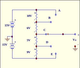 5.
Define Vo for the circuit to the right.
5.
Define Vo for the circuit to the right.
A.1V B. – 1V C. 6V D. 5V E. – 5V
Solution:
Equivalent circuit is
By KVL: 10 + 6 + v0 – 15 = 0; v0 = –1V
Answer: B.
16. Define Thevenin voltage for the circuit in Fig.9.
A.9V B. 8V C. 6V D. 5V E. 3V
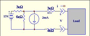
Fig. 9
Solution:
E quivalent
current source will be 15/3*103=5mA
quivalent
current source will be 15/3*103=5mA
E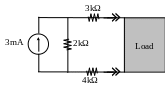 quivalent
current source and resistors in parallel will be 5–2=3mA and
6*3/9=2kΩ
quivalent
current source and resistors in parallel will be 5–2=3mA and
6*3/9=2kΩ
Equivalent voltage source and resistors in series will be 3*2=6 and 4+2+3=9kΩ
Load


Answer: C.
17.Equivalent resistance of parallel arrangement is equal to 6 Ω. Two resistors are connected in a parallel, one of them is 10 Ω. What is the second one?
A.15 Ω B.20 Ω C. 10 Ω D. 12 Ω E. 8 Ω
Solution:
REQ for two
parallel branches is
![]() .
We know that REQ=6
and one of the resistors equals 10.
Let the second one will be X.
Substituting these values gives equation
.
We know that REQ=6
and one of the resistors equals 10.
Let the second one will be X.
Substituting these values gives equation
![]() .
Solving for X gives us X=15.
.
Solving for X gives us X=15.
Answer: A.
18. Find the correct formula for p. p=
A. vi B. dw/dq C.dq/dt D. dq/dv E. di/dt
Solution: p=dw/dt=vi.
Answer: A.
19. The parameters of the Thevenin and Norton equivalent circuits at a given interface can be found as
A. vT=vSC iN=iOC RN=RT=vOC/iSC B. vT=vOC iN=iSC RN=RT=vOC/iOC
C. vT=vSC iN=iOC RN=RT=vSC/iSC
D. vT=vSC iN=iOC RN=RT=vOC/iOC E. vT=vOC iN=iSC RN=RT=vOC/iSC
Solution:
vT=vOC iN=iSC RN=RT=vOC/iSC
Answer: E.
Fig.3
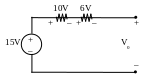
8. For the circuit in Fig.4 define V0. Fig.4
A .
12V B.6V C.4V D.3V E. 10V
.
12V B.6V C.4V D.3V E. 10V
Solution:
Equivalent circuit will be
Now by Voltage Division Rule we have
![]() V
V
Answer: B.
20. For the circuit below RA=RB=100Ω, RC=50 Ω. What is the value of R1?
A. 10 Ω B. 20 Ω C. 30 Ω D. 40 Ω E. 50 Ω

Solution:
![]()
![]()
![]()
Answer: B.
21. Formulate mesh-current equation for mesh A for the circuit in Fig.8.
A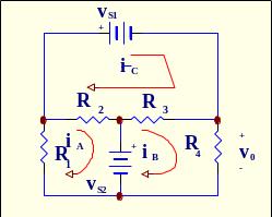 .
(R3+R4)iB-R3iC=
vS2 B. (R1+R2)iA-R2iC=
vS2
.
(R3+R4)iB-R3iC=
vS2 B. (R1+R2)iA-R2iC=
vS2
C. (R3+R2)iC-R3iC- R2iA= vS1
D. (R3+R2)iC-R3iC- R2iA= -vS1 E. (R1+R2)iA-R2iC= - vS2
Solution:
iA(R1+R2) – iCR2= –VS2 Fig.8
Answer: E.
22. For the circuit in Fig.9 resistance of the Thevenin equivalent RT is equal to _____
A. 3Ω B. 5kΩ C. 6kΩ D. 8kΩ E. 9kΩ
Answer: E.
23. For ideal open circuit we have got i =_____, R= ____, for ideal short circuit we have got v =_____, R=_____.
A.0, 0, 0, 0 B. ∞, 0, 0, 0 C.0, ∞, 0, 0 D. 0, 0, ∞, 0 E. 0, 0,0, ∞
Solution:
i=0 when R=∞. It’s an open circuit. v=0 when R=0. It’s a short circuit.
Answer: C.
24. For inductor the i-v-relationship is:
A.iL(t)=(dvC(t)/dt) B. iL(t)= L (dvC(t)/dt) C. vL(t) =L(diL(t)/dt)
D. vL(t) =(diL(t)/dt) E. vL(t) =RL(diL(t)/dt)
Answer: C.
25. For series RLC circuit for solution of differential equation the characteristic equation is:
A. RCs2+LC+1=0 B. LCs2+RC+1=0 C. LRCs2+LC+1=0
D. LCs2+RTCs+1=0 E. LCs2+RTC+1=0
Solution:
Differential equation for series RLC circuit is
![]()
The characteristic equation is
LCs2+RTCs+1=0
Answer: D.