

5. Means and methods of electronic reproduction
5.1 Device components
5.1.1 Optical elements
5.1.2 Light sources
5.1.3 Photoelectric transducers
5.2 Image capturing devices
5.2.1 Electrooptical analysis
5.2.2 Scan spot size, sampling frequency, image file volume
5.2.3 Scanning by the CCD array
5.2.4 Four channel scanner
5.2.5 Spectral sensitivities of a capturing device
5.3 Output
5.3.1 Methods and means of an image output
5.3.2 Electromechanical recording
5.3.3 Gravure cylinders preparation
5.3.4 Laser engraving
5.3.5 Digital printing
5.4 Films and plates recording
5.4.1 General characteristics
5.4.2 Capstan devices
5.4.3 On-drum and in-drum recording
5.4.4 “Hard” and “soft” dots
Key summary issues
Tests
5. Means and methods of electronic reproduction
5.1 Device components
5.1.1 Optical elements
Optical elements of image capturing and recording systems are filters, diaphragms, diffraction gratings, prisms, lenses, optical fibers, mirrors.... The latter are made of special optical glass with high uniformity of properties, without foreign inclusions, sweeps, bubbles, etc.
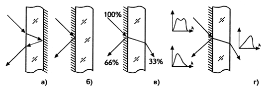
The main purpose of mirrors is to change the light flux direction. Unlike a household mirror the reflecting surface of its optical analogue is not internal, but external, facing the incident light (Figure 5.1,a, b). Losses and distortions caused by scattering, multiple internal reflection and refraction of light in the glass thickness are thereby reduced.
|
Figure 5.1 Usual (a) and optical: direction changing (b), beam-splitting (c) and dichroic (d) mirrors
The translucent mirror not only changes the light beam direction, but also divides its energy in a given ratio (Figure 5.1, c). Its kind is a dichroic mirror with a colored layer separating the beam also by its spectral content. In figure 5.1 (d) this property is schematically indicated by the differences in the spectral characteristics of the incident, reflected and transmitted light. Dichroic mirrors, along with prisms, diffraction gratings and color filters, are also used for color separation. Of all these elements, the latter has the lowest energy efficiency, since the absorbed part of the light is irreversibly lost and is not used to form other color-separated signals in the image capturing. Neutral or "gray" filters are used to calibrate the intensity of light without changing its color. To smoothly adjust the light intensity, an optical wedge is used, the transmission of which is determined by the thickness of its portion placed in the optical channel, or a glass disk with a translucent track of variable optical density. Diaphragms are primarily used to set the sampling element in the scanning system. If it is necessary to use scan spots of different sizes, variable (iris) diaphragms or a set of diaphragms of fixed size are used. The aperture, the size of which takes into account the print screen ruling and the image magnification, is set in the optical channel manually or automatically. Glass optical fibers allow:
Biconvex lens (Figure 5.2) is mainly used to build an image of the illuminated area of an original in the plane of the diaphragm, which specifies the sampling area, or on the sensitive layer of the photoelectrical transducer (PET). In geometric optics, the image is understood as the place of the points at which the rays reflected by the corresponding points of the imaged object converge. In this application, such piece of glass serves as a lens. It is also called a condenser, when, for example, to achieve maximum intensity, the radiation transmitted through it is fixed in the plane of its rays greatest concentration at the point F (Figure 5.2), where all rays parallel to the optical axis before entering the lens meet. |
|
Fig. 5.2 Imaging and concentration of the light energy by the lens |

Important optical element of a graphic scanner is the original carrying transparent drum. The scan spot size is measured in units of microns. So, with significant dimensions, the accuracy with which the drum thickness and diameter are maintained in the manufacture and operation is also units of microns.