

Solas_consolidated_2009
.pdfPart A-l: Structure of ships
Regulation 3-6
Regulation 3-4
Emergency towing arrangements on tankers
1 Emergency towing arrangements shall be fitted at both ends on board every tanker of not less than 20,000 tonnes deadweight.
2For tankers constructed on or after 1 July 2002:
.1 the arrangements shall, at all times, be capable of rapid deployment in the absence of main power on the ship to be towed and easy connection to the towing ship. At least one of the emergency towing arrangements shall be pre-rigged ready for rapid deployment; and
.2 emergency towing arrangements at both ends shall be of adequate strength, taking into account the size and deadweight of the ship and the expected forces during bad weather conditions. The design and construction and prototype testing of the emergency towing arrangements shall be approved by the Administration, based on the Guidelines developed by the Organization.
3 For tankers constructed before 1 July 2002, the design and construction of emergency towing arrangements shall be approved by the Administration, based on the Guidelines developed by the Organization.*
Regulation 3-5
New installation of materials containing asbestos
1 This regulation shall apply to materials used for the structure, machinery, electrical installations and equipment covered by the present Convention.
2 For all ships, new installation of materials which contain asbestos shall be prohibited except for:
.1 vanes used in rotary vane compressors and rotary vane vacuum pumps;
.2 watertight joints and linings used for the circulation of fluids when, at high temperature (in excess of 350°C) or pressure (in excess of 7 x 10 Pa), there is a risk of fire, corrosion or toxicity; and
.3 supple and flexible thermal insulation assemblies used for temperatures above 1,000°C.
Regulation 3-6
Access to and within spaces in, and forward of, the cargo area of oil tankers and bulk carriers
1Application
1.1Except as provided for in paragraph 1.2, this regulation applies to oil tankers of 500 gross tonnage and
over and bulk carriers, as defined in regulation I X / 1 , of 20,000 gross tonnage and over, constructed on or after 1 January 2006 .
1.2 Oil tankers of 500 gross tonnage and over constructed on or after 1 October 1994 but before 1 January 2005 shall comply with the provisions of regulation II-1/12-2 adopted by resolution MSC . 27(61) .
2 Means of access to cargo and other spaces
2.1 Each space shall be provided with means of access to enable, throughout the life of a ship, overall and close-up inspections and thickness measurements of the ship's structures to be carried out by the Administration, the Company, as defined in regulation IX/1 , and the ship's personnel and others as necessary. Such means of access shall comply with the requirements of paragraph 5 and with the Technical provisions for means of access for inspections, adopted by the Maritime Safety Committee by resolution MSC.133(76), as may be amended by the Organization, provided that such amendments are adopted, brought into force and
* Refer to the Guidelines on emergency towing arrangements for tankers adopted by the Maritime Safety Committee by resolution MSC.35(63), as may be amended.
37
Chapter ll-l: |
Construction |
- structure, |
stability, |
installations |
Regulation 3-6 |
|
|
|
|
take effect in accordance with the provisions of article VIII of the present Convention concerning the amendment procedures applicable to the Annex other than chapter I.
2.2Where a permanent means of access may be susceptible to damage during normal cargo loading and unloading operations or where it is impracticable to fit permanent means of access, the Administration may allow, in lieu thereof, the provision of movable or portable means of access, as specified in the Technical provisions, provided that the means of attaching, rigging, suspending or supporting the portable means of access forms a permanent part of the ship's structure. All portable equipment shall be capable of being readily erected or deployed by ship's personnel.
2.3The construction and materials of all means of access and their attachment to the ship's structure shall be to the satisfaction of the Administration. The means of access shall be subject to survey prior to, or in conjunction with, its use in carrying out surveys in accordance with regulation 1/10.
3 Safe access to cargo holds, cargo tanks, ballast tanks and other spaces
3.1 Safe access* to cargo holds, cofferdams, ballast tanks, cargo tanks and other spaces in the cargo area shall be direct from the open deck and such as to ensure their complete inspection. Safe access to double bottom spaces or to forward ballast tanks may be from a pump-room, deep cofferdam, pipe tunnel, cargo hold, double hull space or similar compartment not intended for the carriage of oil or hazardous cargoes.
3.2 Tanks, and subdivisions of tanks, having a length of 35 m or more, shall be fitted with at least two access hatchways and ladders, as far apart as practicable. Tanks less than 35 m in length shall be served by at least one_ access hatchway and ladder. When a tank is subdivided by one or more swash bulkheads or similar obstructions which do not allow ready means of access to the other parts of the tank, at least two hatchways and ladders shall be fitted.
3.3 Each cargo hold shall be provided with at least two means of access as far apart as practicable. In general, these accesses should be arranged diagonally, for example one access near the forward bulkhead on the port side, the other one near the aft bulkhead on the starboard side.
4 Ship Structure Access Manual
4.1 A ship's means of access to carry out overall and close-up inspections and thickness measurements shall be described in a Ship Structure Access Manual approved by the Administration, an updated copy of which shall be kept on board. The Ship Structure Access Manual shall include the following for each space:
.1 plans showing the means of access to the space, with appropriate technical specifications and dimensions;
.2 plans showing the means of access within each space to enable an overall inspection to be carried out, with appropriate technical specifications and dimensions. The plans shall indicate from where each area in the space can be inspected;
.3 |
plans showing the means of access within the space to enable close-up inspections to be carried |
|
out, with appropriate technical specifications and dimensions. The plans shall indicate the |
|
positions of critical structural areas, whether the means of access is permanent or portable and |
|
from where each area can be inspected; |
.4 |
instructions for inspecting and maintaining the structural strength of all means of access and |
|
means of attachment, taking into account any corrosive atmosphere that may be within the |
|
space; |
.5 |
instructions for safety guidance when rafting is used for close-up inspections and thickness |
|
measurements; |
.6 |
instructions for the rigging and use of any portable means of access in a safe manner; |
.7 |
an inventory of all portable means of access; and |
.8 |
records of periodical inspections and maintenance of the ship's means of access. |
* Refer to the Recommendations for entering enclosed spaces aboard ships, adopted by the Organization by resolution A.864(20).
38
Part A-l: Structure oj ships
Regulation 3-8
4.2For the purpose of this regulation "critical structural areas" are locations which have been identified
from calculations to require monitoring or from the service history of similar or sister ships to be sensitive to cracking, buckling, deformation or corrosion which would impair the structural integrity of the ship.
5 General technical specifications
5.1 For access through horizontal openings, hatches or manholes, the dimensions shall be sufficient to allow a person wearing a self-contained air-breathing apparatus and protective equipment to ascend or descend any ladder without obstruction and also provide a clear opening to facilitate the hoisting of an injured person from the bottom of the space. The minimum clear opening shall not be less than 600 mm x 600 mm. When access to a cargo hold is arranged through the cargo hatch, the top of the ladder shall be placed as close as possible to the hatch coaming. Access hatch coamings having a height greater than 900 mm shall also have steps on the outside in conjunction with the ladder.
5.2 For access through vertical openings, or manholes, in swash bulkheads, floors, girders and web frames providing passage through the length and breadth of the space, the minimum opening shall be not less than 600 mm x 800 mm at a height of not more than 600 mm from the bottom shell plating unless gratings or other footholds are provided.
5.3 For oil tankers of less than 5,000 tonnes deadweight, the Administration may approve, in special circumstances, smaller dimensions for the openings referred to in paragraphs 5.1 and 5.2, if the ability to traverse such openings or to remove an injured person can be proved to the satisfaction of the Administration.
Regulation 3-7
Construction drawings maintained on board and ashore
1 A set of as-built construction drawings* and other plans showing any subsequent structural alterations shall be kept on board a ship constructed on or after 1 January 2007.
2 An additional set of such drawings shall be kept ashore by the Company, as defined in regulation IX/1.2.
Regulation 3-8
Towing and mooring equipment
1 This regulation applies to ships constructed on or after 1 January 2007, but does not apply to emergency towing arrangements provided in accordance with regulation 3-4.
2Ships shall be provided with arrangements, equipment and fittings of sufficient safe working load to enable the safe conduct of all towing and mooring operations associated with the normal operation of the ship.
3Arrangements, equipment and fittings provided in accordance with paragraph 2 shall meet the appropriate requirements of the Administration or an organization recognized by the Administration under regulation 1/6.f
4Each fitting or item of equipment provided under this regulation shall be clearly marked with any restrictions associated with its safe operation, taking into account the strength of its attachment to the ship's structure.
* Refer to MSC/Circ.l 135 on As-built construction drawings to be maintained on board the ship and ashore, t Refer to MSC/Circ.l 175 on Guidance on shipboard towing and mooring equipment.
39
Chapter II-l: Construction - structure, stability, |
installations |
Regulation 4
Part B
Subdivision and stability
Regulation 4
General
1 The damage stability requirements in Parts B - l through B - 4 shall apply to cargo ships of 80 m in length (L) and upwards and to all passenger ships regardless of length but shall exclude those cargo ships which are shown to comply with subdivision and damage stability regulations in other instruments* developed by the Organization.
2 The Administration may, for a particular ship or group of ships, accept alternative methodologies if it is satisfied that at least the same degree of safety as represented by these regulations is achieved. Any Administration which allows such alternative methodologies shall communicate to the Organization particulars thereof.
3 Ships shall be as efficiently subdivided as is possible having regard to the nature of the service for which they are intended. The degree of subdivision shall vary with the subdivision length (Ls ) of the ship and with the service, in such manner that the highest degree of subdivision corresponds with the ships of greatest subdivision length (L s ) , primarily engaged in the carriage of passengers.
4 Where it is proposed to fit decks, inner skins or longitudinal bulkheads of sufficient tightness to seriously restrict the flow of water, the Administration shall be satisfied that proper consideration is given to beneficial or adverse effects of such structures in the calculations.
Cargo ships shown to comply with the following regulations may be excluded from the application of part B - l :
.1 Annex I to MARPOL 73/78, except combination carriers (as defined in regulation II-2/3.14) with type B freeboards are not excluded;
.2 International Bulk Chemical Code;
.3 International Gas Carrier Code;
.4 Guidelines for the design and construction of offshore supply vessels (resolution A.469(XII));
.5 Code of Safety for Special Purpose Ships (resolution A.534(13), as amended);
.6 Damage stability requirements of regulation 27 of the 1966 Load Lines Convention as applied in compliance with resolutions A.320(IX) and A.514(13), provided that in the case of cargo ships to which regulation 27(9) applies, main transverse watertight bulkheads, to be considered effective, are spaced according to paragraph (12)(f) of resolution A.320(IX), except ships intended for the carriage of deck cargo; and
.7 Damage stability requirements of regulation 27 of the 1988 Load Lines Protocol, except ships intended for the carriage of deck cargo.
40
Part B-l: Stability
Regulation 5-1
Part B-l
Stability
Regulation 5
Intact stability information*
1 Every passenger ship regardless of size and every cargo ship having a length (L) of 24 m and upwards shall be inclined upon its completion and the elements of its stability determined.
2 The Administration may allow the inclining test of an individual cargo ship to be dispensed with, provided basic stability data are available from the inclining test of a sister ship and it is shown to the satisfaction of the Administration that reliable stability information for the exempted ship can be obtained from such basic data, as required by regulation 5 - 1 . A weight survey shall be carried out upon completion and the ship shall be inclined whenever, in comparison with the data derived from the sister ship, a deviation from the lightship displacement exceeding 1% for ships of 160 m or more in length and 2% for ships of 50 m or less in length and as determined by linear interpolation for intermediate lengths or a deviation from the lightship longitudinal centre of gravity exceeding 0 . 5 % of Ls is found.
3 The Administration may also allow the inclining test of an individual ship or class of ships especially designed for the carriage of liquids or ore in bulk to be dispensed with when reference to existing data for similar ships clearly indicates that, due to the ship's proportions and arrangements, more than sufficient metacentric height will be available in all probable loading conditions.
4 Where any alterations are made to a ship so as to materially affect the stability information supplied to the master, amended stability information shall be provided. If necessary, the ship shall be re-inclined. The ship shall be re-inclined if anticipated deviations exceed one of the values specified in paragraph 5.
5 At periodical intervals not exceeding five years, a lightweight survey shall be carried out on all passenger ships to verify any changes in lightship displacement and longitudinal centre of gravity. The ship shall be re-inclined whenever, in comparison with the approved stability information, a deviation from the lightship displacement exceeding 2% or a deviation of the longitudinal centre of gravity exceeding 1% of Ls is found or anticipated.
6 Every ship shall have scales of draughts marked clearly at the bow and stern. In the case where the draught marks are not located where they are easily readable, or operational constraints for a particular trade make it difficult to read the draught marks, then the ship shall also be fitted with a reliable draught indicating system by which the bow and stern draughts can be determined.
Regulation 5-1
Stability information to be supplied to the master^
1 The master shall be supplied with such information satisfactory to the Administration as is necessary to enable him by rapid and simple processes to obtain accurate guidance as to the stability of the ship under varying conditions of service. A copy of the stability information shall be furnished to the Administration.
2 The information should include:
.1 curves or tables of minimum operational metacentric height (GM) versus draught which assures compliance with the relevant intact and damage stability requirements, alternatively
*Refer to the Code on Intact Stability for All Types of Ships covered by IMO Instruments, adopted by the Organization by resolution A.749(18), as amended. From 1 July 2010, the International Code on Intact Stability, 2008, adopted by resolution MSC.267(85), is expected to enter into force.
*Refer also to the Guidelines for the preparation of intact stability information (MSC/Circ.456); Guidance on the intact stability of existing tankers during transfer operations (MSC/Circ.706); and the Revised Guidance to the master for avoiding dangerous situations in adverse weather and sea conditions (MSC.1/Circ.1228).
41
Chapter 11-1: Construction - structure, stability, |
installations |
Regulation 6 |
|
corresponding curves or tables of the maximum allowable vertical centre of gravity (KG) versus draught, or with the equivalents of either of these curves;
.2 instructions concerning the operation of cross-flooding arrangements; and
.3 all other data and aids which might be necessary to maintain the required intact stability and stability after damage.
3 The stability information shall show the influence of various trims in cases where the operational trim range exceeds ± 0 . 5 % of L s .
4For ships which have to fulfil the stability requirements of part B - l , information referred to in paragraph 2 is determined from considerations related to the subdivision index, in the following manner: Minimum required GM (or maximum permissible vertical position of centre of gravity KG) for the three draughts ds, dp and d\ are equal to the GM (or KG values) of corresponding loading cases used for the calculation of survival factor st. For intermediate draughts, values to be used shall be obtained by linear interpolation applied to the GM value only between the deepest subdivision draught and the partial subdivision draught and between the partial load line and the light service draught respectively. Intact stability criteria will also be taken into account by retaining for each draft the maximum among minimum required GM values or the minimum of maximum permissible KG values for both criteria. If the subdivision index is calculated for different trims, several required GM curves will be established in the same way.
5When curves or tables of minimum operational metacentric height (GM) versus draught are not appropriate, the master should ensure that the operating condition does not deviate from a studied loading - condition, or verify by calculation that the stability criteria are satisfied for this loading condition.
Regulation 6
Required subdivision index R*
1 The subdivision of a ship is considered sufficient if the attained subdivision index A, determined in accordance with regulation 7, is not less than the required subdivision index R calculated in accordance with this regulation and if, in addition, the partial indices As, Ap and A[ are not less than 0 . 9R for passenger ships and 0.5-R for cargo ships.
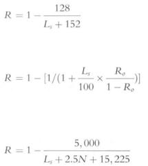
2 For all ships to which the damage stability requirements of this chapter apply, the degree of subdivision to be provided shall be determined by the required subdivision index R, as follows:
.1 In the case of cargo ships greater than 100 m in length (Ls):
.2 In the case of cargo ships not less than 80 m in length (Ls) and not greater than 100 m in length
(Ls):
where R0 is the value of R as calculated in accordance with the formula in subparagraph . 1 .
.3 In the case of passenger ships:
* The Maritime Safety Committee, in adopting the regulations contained in parts B to B - 4, invited Administrations to note that the regulations should be applied in conjunction with the explanatory notes developed by the Organization in order to ensure their uniform application.
42
Part B-l: Stability
Regulation 7
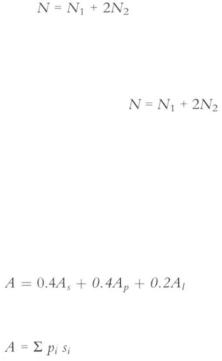
where:
 = number of persons for whom lifeboats are provided
 = number of persons (including officers and crew) the ship is permitted to carry in excess o f N\.
.4 Where the conditions of service are such that compliance with paragraph 2.3 of this regulation on the basis of is impracticable and where the Administration considers that a suitably reduced degree of hazard exists, a lesser value of N may be taken but in no case less than 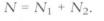
Regulation 7
Attained subdivision index A
1 The attained subdivision index A is obtained by the summation of the partial indices As, Ap and A[,
(weighted as shown) calculated for the draughts ds, dp and d\ defined in regulation 2 in accordance with the following formula:
Each partial index is a summation of contributions from all damage cases taken in consideration, using the following formula:
Where:
i represents each compartment or group of compartments under consideration,
Pi accounts for the probability that only the compartment or group of compartments under consideration may be flooded, disregarding any horizontal subdivision, as defined in regulation 7 - 1 ,
Si accounts for the probability of survival after flooding the compartment or group of compartments under consideration, and includes the effect of any horizontal subdivision, as defined in regulation 7 - 2 .
2 In the calculation of A, the level trim shall be used for the deepest subdivision draught and the partial subdivision draught. Th e actual service trim shall be used for the light service draught. If, in any service condition, the trim variation in comparison with the calculated trim is greater than 0 . 5 % of Ls, one or more additional calculations of A are to be submitted for the same draughts but different trims so that, for all service conditions, the difference in trim in comparison with the reference trim used for one calculation will be less than 0 . 5 % of Ls.
3When determining the positive righting lever (GZ) of the residual stability curve, the displacement used should be that of the intact condition. That is, the constant-displacement method of calculation should be used.
4The summation indicated by the above formula shall be taken over the ship's subdivision length (L,) for all cases of flooding in which a single compartment or two or more adjacent compartments are involved. In the case of unsymmetrical arrangements, the calculated A value should be the mean value obtained from calculations involving both sides. Alternatively, it should be taken as that corresponding to the side which evidently gives the least favourable result.
5Wherever wing compartments are fitted, contribution to the summation indicated by the formula shall be taken for all cases of flooding in which wing compartments are involved. Additionally, cases of simultaneous flooding of a wing compartment or group of compartments and the adjacent inboard compartment or group of compartments, but excluding damage of transverse extent greater than one half of the ship breadth B, may be added. For the purpose of this regulation, transverse extent is measured
inboard from ship's side, at right angles to the centreline at the level of the deepest subdivision draught.
6 In the flooding calculations carried out according to the regulations, only one breach of the hull and only one free surface need to be assumed. The assumed vertical extent of damage is to extend from the
43

Chapter ll-l: |
Construction |
- |
structure, |
stability, |
installations |
Regulation 7-1 |
|
|
|
|
|
baseline upwards to any watertight horizontal subdivision above the waterline or higher. However, if a lesser extent of damage will give a more severe result, such extent is to be assumed.
7 If pipes, ducts or tunnels are situated within the assumed extent of damage, arrangements are to be made to ensure that progressive flooding cannot thereby extend to compartments other than those assumed flooded. However, the Administration may permit minor progressive flooding if it is demonstrated that its effects can be easily controlled and the safety of the ship is not impaired.
Regulation 7-1
Calculation of the factor pi
1 The factory, for a compartment or group of compartments shall be calculated in accordance with paragraphs 1.1 and 1.2 using the following notations:
j |
= |
the aftmost damage zone number involved in the damage starting with No . l at the stern; |
|
n |
= |
the number of adjacent damage zones involved in the damage; |
|
k |
= |
the number of a particular longitudinal bulkhead as barrier for transverse penetration in a |
|
|
|
damage zone counted from shell towards the centreline. Th e shell has k = 0; |
|
x\ |
= |
the distance from the aft terminal of Ls to |
the aft end of the zone in question; |
x2 = |
the distance from the aft terminal of Ls to |
the forward end of the zone in question; |
|
b |
= |
the mean transverse distance in metres measured at right angles to the centreline at the " |
|
|
|
deepest subdivision load line between the shell and an assumed vertical plane extended |
|
|
|
between the longitudinal limits used in calculating the factory, and which is a tangent to, or |
|
|
|
common with, all or part of the outermost portion of the longitudinal bulkhead under |
|
|
|
consideration. This vertical plane shall be so orientated that the mean transverse distance to |
|
|
|
the shell is a maximum, but not more than twice the least distance between the plane and |
|
|
|
the shell. If the upper part of a longitudinal bulkhead is below the deepest subdivision load |
|
|
|
line the vertical plane used for determination of b is assumed to extend upwards to the |
|
|
|
deepest subdivision waterline. In any case, |
b is not to be taken greater than B/2. |
If the damage involves a single zone only:
If the damage involves two adjacent zones:
If the damage involves three or more adjacent zones:
and where 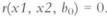
1.1 The factor p(xl, x2) is to be calculated according to the following formulae:
44
Overall normalized max damage length: MaximumProbabilityLengthKnuckleCumulativwherpoinprobabilitabsolutedensitnormalizeytheatydamagdistribuJ e^ nlength::ributionion: ends:
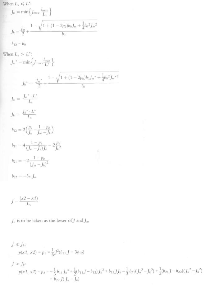
The non-dimensional damage length:
The normalized length of a compartment or group of compartments:
1.1.1 Where neither limit of the compartment or group of compartments under consideration coincides with the aft or forward terminals:

Chapter 11-1: |
Construction - structure, stability, installations |
Regulation 7-2 |
|
1.1.2 Where |
the aft limit of the compartment or group of compartments under consideration coincides |
with the aft terminal or the forward limit of the compartment or group of compartments under consideration coincides with the forward terminal:
1.1.3 Where the compartment or groups of compartments considered extends over the entire subdivision length (L s ):
1.2The factor r{xi, x2, b) shall be determined by the following formulae:
G
where:
1.2.1Where the compartment or groups of compartments considered extends over the entire subdivision length (L<):
1.2.2Where neither limit of the compartment or group of compartments under consideration coincides with the aft or forward terminals:
1.2.3 Where |
the aft limit of the compartment or group of compartments under consideration coincides |
with |
the forward limit of the compartment or group of compartments under |
|
h the forward terminal: |
Regulation 7-2
Calculation of the factor s,
1 The factor 5,- shall be determined for each case of assumed flooding, involving a compartment or group of compartments, in accordance with the following notations and the provisions in this regulation.
0(, is the equilibrium heel angle in any stage of flooding, in degrees;
0„ is the angle, in any stage of flooding, where the righting lever becomes negative, or the angle at which an opening incapable of being closed weathertight becomes submerged;
G Z n i a x is the maximum positive righting lever, in metres, up to the angle 0„;
Range is the range of positive righting levers, in degrees, measured from the angle 0( > . Th e positive range is to be taken up to the angle 0„;
46