


Station design an^.Jayo'ut-^
2.17. Consideration is being given to adopting a central control room location adjacent to the mechanical annexe for the future 2 x 900 MW stations.
Vertical communication must also be given adequate
consideration and |
stairways and lifts need to be |
correctly integrated |
with horizontal access facilities. |
For larger items of equipment and infrequent major plant movements, hoisting wells should be provided at strategic locations throughout the station, again being co-ordinated with horizontal access routes.
6Station layout
6.1General
Station layout is concerned with the logical and econ omic use of space and the relationship of one piece of plant with another.
Chapter 2
An efficient layout of plant and systems minimises losses and therefore running costs. Ideally, plant items should be located as close as practical, but the designer has to ensure that adequate access for operation and maintenance is provided. The best overall design there fore is one which strikes the correct balance between lowest cost and the best arrangement from both con structional and operational points of view.
Given that the overall station design is a compromise of the various factors, it is still the aim on the grounds of economy to keep the overall main building dimen sions to a minimum, and it is left to the ingenuity of the designer and the utility experience to determine the correct balance to accept between the competing variables.
Over the years, the basic layout of stations in the CEGB has developed into a general standard pattern, irrespective of the number of generating units installed. However, the overall plant 'arrangement within the
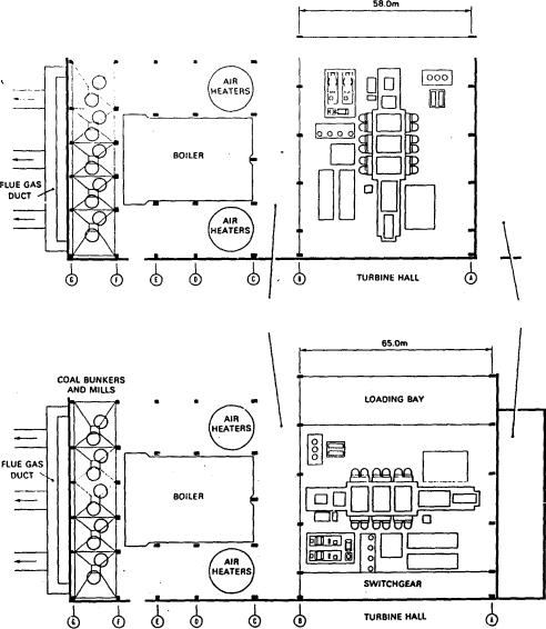
Fig. 2.17 Typical main buildings plant layout 4 x 500 MW transverse sets
78
building envelope has varied depending upon the design and manufacture of the main plant items, particularly boiler and turbine.
This basic pattern consists of an integrated building structure with boiler and turbine houses arranged in parallel but usually separated by an annexe containing mechanical and electrical auxiliary plant items and systems. To the rear of the boiler house are located the precipitators and chimney, whilst on the open side of the turbine hall are usually located the transformers and some auxiliary switchgear. Figures 2.18 to 2.21 inclusive show a number of station arrangements illus trating these principles.
6.2 Main plant orientation
The single most important decision which influences overall station layout is perhaps the choice of the
Station layout
relationship between the turbine-generator and the boiler, since both the boiler centreline spacing and dimensions of the turbine hall can be significantly influenced by this decision. It is not a simple decision.
Traditional practices, |
the |
choice of |
plant supplier, |
plant specification, |
the |
relationship |
between civil |
and electrical and mechanical engineering costs, the scope of supply of particular contractors, site re straints and perhaps even the engineers’ likes and dislikes may influence the final outcome. The overall number of permutations which can be developed
considering |
all |
the |
potentially variable |
factors is |
|
large, |
but in |
practice |
the decision often comes down |
||
to the |
choice |
of a |
few options which |
experience |
|
within a utility has shown to provide economic and practical solutions. These are illustrated in Fig 2.18 to 2.21.
COAL BUNKERS
AND MILLS
MECHANICAL |
TRANSFORMERS |
|
ANNEXE |
||
|
Fig* 2.18 Longitudinal and transverse arrangements of 6-flow LP turbine-generators
79
Station design aT!$ layout |
|
|
|
|
|
|
|
|
|
|
|
|
|
|
Chapter 2 |
|||||||
6.2.1 |
Turbine-generator plant |
|
|
|
|
|
|
|
also be made for adequate access and loading bays and |
|||||||||||||
With |
fossil-fired plant, |
the |
initial |
determination |
is |
for the |
provision of |
laydown areas for |
machine |
parts |
||||||||||||
during overhaul. |
|
|
|
|
|
|
||||||||||||||||
between |
transverse, |
longitudinal |
or |
angled |
layout |
of |
|
|
|
|
|
|
||||||||||
The 660 MW unit plan in Fig 2.19 shows that with |
||||||||||||||||||||||
the turbine-generator. With 4-flow |
low |
pressure (LP) |
||||||||||||||||||||
4-flow |
LP turbines, |
the |
turbine hall |
dimensions |
are |
|||||||||||||||||
turbines, |
the |
overall |
dimensions |
of |
the turbine |
with |
the |
|||||||||||||||
little affected whether a |
longitudinal |
or |
transverse |
|||||||||||||||||||
condensing, |
feedheating |
and |
general |
turbine |
auxiliary |
arrangement is adopted. Generator rotor withdrawal |
||||||||||||||||
plant alongside produces a plan area approximately |
||||||||||||||||||||||
space may marginally increase the width needed for a |
||||||||||||||||||||||
square. With a 6-flow LP turbine, a similar arrange |
transverse arrangement and |
so requires |
a |
slightly larger |
||||||||||||||||||
ment |
of |
auxiliary |
equipment |
produces |
a |
rectangular |
, crane span, but the advantage of the shortest possible |
|||||||||||||||
area. |
|
|
|
|
|
|
|
|
|
|
|
|
|
symmetrical main steam and reheat pipework routes |
||||||||
These areas must be covered by the main overhead |
•'offsets this feature. |
|
|
|
|
|
|
|||||||||||||||
cranes or have individual facilities, so the plan area of |
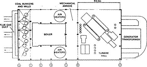
An angled 660 MW 6-flow LP turbine-generator can |
|||||||||||||||||||||
the turbine hall follows from the alignment of the |
produce a compact turbine hall arrangement |
as shown |
||||||||||||||||||||
approximate |
number |
of |
units |
installed. Provision must |
in Fig 2.20. Complications can arise in utilising the |
|
||||||||||||||||
|
|
|
|
|
|
|
|
|
|
|
|
|
|
|
58.0m |
|
|
|
|
|
|
|
|
|
|
|
|
|
|
|
|
|
|
|
|
|
|
--------------------------------------------I |
|
|
|
|
|||
COAL BUNKERS
ANO MILLS
LOADING BAY
MECHANICAL
Fig. 2.19 Longitudinal and transverse arrangements of 4-flow LP turbine-gcncralors
80
Station layout
Fig. 2.20 Diagonal layout arrangement of 6-flow LP turbine generators
remaining triangular areas to give a good layout of auxiliary plant and in the control of the crane motions.
The 6-l'low LP turbine arranged longitudinally pro duces a narrower turbine hall with minimum span main cranes. Against this is the disadvantage of longer, asymmetrical main steam and reheat pipework and generally tin increase in boiler centreline splicing.
With a 660 MW 6-flow LP turbine arranged trans versely, a wider turbine hall is required necessitating • a larger span crane, but again this is offset by gains in main steampipe layout. The long crane span can be split by providing two cranes on separate parallel longitudinal rails, but the complication of the support ing columns splitting the turbine hall and the conse quent associated blind spots, not approachable by the cranes, must be considered.
The same disadvantage applies if, in a transverse arrangement of turbine-generator sets, separate cranes are provided longitudinally over each set. Erection and maintenance requirements are likely to demand a minimum of four independent cranes.
6.2.2Boiler plant
The minimum boiler spacing or centreline distance is normally controlled by the layout of auxiliary plant items such as long lance sootblowers, mills, bunkers, fans, ducting and airheaters which often extend beyond the net furnace width. These minimum dimensions can only usually be achieved when utilising a trans verse turbine-generator layout and boiler spacing is often increased when using longitudinal turbine
arrangements.
It is also necessary to consider which way the boilers will face relative to the turbine hall; whether the firing wall (or the furnace in the case of corner-fired boilers) is to be on the turbine side or the remote side, as
illustrated in Fig 2.21.
If the firing wall is to be on the turbine side, then front-firing favours the positioning of coal bunkers,
feeders and pulverised fuel (PF) mills between the boiler and turbine for economic pulverised fuel pipe routing. A possible disadvantage with this arrangement is the introduction of noise and potential dust problems into the centre of the station and lengthening of main steam and reheat pipes through housing to cross the bunker bay. This arrangement however minimises flue duct lengths to the precipitators.
Turning the complete boiler plant through 180° to locate the coal bunkers and mills at the rear of the boiler house, reduces some of the potential problems of the turbine side arrangement, but the gas flows are now remote from the precipitators. Additional ducting is required to carry flue gas around the boiler and the boiler width overall is then increased.
With oil-fired boilers, a longitudinal arrangement of 6-flow LP turbines requires the boilers to be opened out from minimum centres. With a 4-flow LP turbine the transverse arrangement with boilers on minimum centres gives a compact overall station layout.
An alternative arrangement of boiler plant is possible where the coal bunkers, feeders and pulverised fuel mills are located on either side of the boiler. Such an arrangement extends considerably the spacing or centreline distances of the boilers and therefore is most suited to a station design utilising longitudinal turbine
arrangements.
The CEGB has only adopted this layout practice when corner-fired boilers have been installed and the furnace is located towards the turbine hall.
The boiler is the largest single item of plant in the power station and in conjunction with its auxiliary plant, such as pulverising mills, fans, airheaters, soot blowers, etc., presents a major layout exercise to ensure the often conflicting requirements of minimum capital cost and adequate access for erection and maintenance are correctly evaluated.
Many utilities prepare reference designs for overall power station designs, but it is usually in the boiler area where such a philosophy cannot always be applied due
81