


btauon design |
Chapter 2 |
|
58.0m |
|
COAL BUNKERS |
|
AND MILLS |
Fig. 2.21 Layouts showing alternative boiler orientations
to the influence that the choice of fuel and its properties exert on the plant design.
Figures 2.22, 2.23 and 2.24 show how such factors influence both the boiler design and also the choice and layout of auxiliary plant. Such variations can obviously have a major impact on overall station design directly by the addition or omission of equipment, or by the relationship of weight and size of the boiler to the supporting structure and enclosure envelope. Second ary areas such as the storage volume of coal bunkers and the type and capacity rating of auxiliary plant such as coal pulverising mills, fans, etc., are also determined by these factors and can influence some of the principal
overall dimensions of the station layout, particularly the minimum boiler centreline spacing.
6.3 Layout conventions
In reviewing the basic layout concepts outlined, the reader should have identified a number of layout practices which are consistent between all the options discussed. These practices have evolved over the years within the CEGB and have been demonstrated to provide economic and practical designs in a UK situa tion. Such practices are regularly reviewed in relation
82
Station layout
I-'ig. 2.22 500 MW oil-fired boiler and auxiliary plant
to new plant designs and operational procedures and amended accordingly, but represent the knowledge gained by years of experience within the CEGB on station design, construction and operation of large fossil-fired units.
6.3.1 The unit principle
The unit principle is the association of a single turbine generator and boiler, together with its immediate auxiliary services, to form a complete, virtually selfcontained generating unit.
Many power station engineers will be familiar with ‘range’ stations where all boilers steam into a common receiver and from which individual turbine-generators take their supplies. Feedwater is similarly returned to a common receiver from which individual boilers draw their supplies, This arrangement gives the maximum flexibility in relation to overall boiler and turbine availability, but CEGB experience is that the reliability of large modern units makes such a provision unecon
omic. It has therefore been CEGB practice for many years to build completely integrated units where the boiler and turbine are matched in capacity.
Many services however remain as station-based systems, e.g., cooling water system, town water ser vices, fuel handling and storage systems, etc., but this does not invalidate the unit concept.
6.3.2Mirror imaging
‘Mirror imaging’ is the complete or partial handling of plant and systems between pairs of boiler/turbine units to give a symmetrical layout about their common centreline. Such a concept is shown in Fig 2.25.
A mirrored design gives an attractive layout but CEGB experience suggests it has many practical dis advantages. It requires the production of two sets of engineering and design details, encourages manufactur ing and construction errors and it potentially precipi tates operator error.
_____ ......... |
83 |

Station desigtf and layout |
Chapter 2 |
COLUMN
CENTRE
LINES
KEY |
|
|
|
1 |
STEAM DRUM |
24 COAL BUNKER |
|
2 |
FO FAN SUCTION DUCT |
2$ PA FAN |
|
3 |
SECONDARY REHEATER ELEMENTS |
26 |
PA FAN DISCHARGE DUCT |
4 |
PRIMARY REHEATER ELEMENTS |
27 |
PA FAN SUCTION DUCT |
5 |
REAR WALL BURNER AREA VENTILATION DUCT |
28 |
FURNACE HOPPER |
6 |
FD DISCHARGE ANO CROSS OVER DUCT |
20 COLD AIR BUS MAIN |
|
7 |
SOOTBLOWER AIR CONNECTION |
30 |
HOT AIR TO MILLS DUCT |
8 |
PRIMARY SUPERHEATER ELEMENTS |
31 |
MAIN AIRHEATER AIR BY-PASS DUCT |
0 FURNACE GAS EXIT HOPPER |
32 |
HOT AIR RECIRCULATION |
|
10 |
SECONDARY SUPERHEATER ELEMENTS |
33 |
MAIN AIRHEATER AIR OUTLET DUCT |
11 |
PLATEN SUPERHEATER ELEMENTS |
34 |
GAS TO MAIN AIRHEATER |
12 |
RADIANT SUPERHEATER |
35 |
SECONDARY AIR BUS MAIN |
13 |
DESUPERHEATERS |
36 |
SECONDARY AIR TO PLENUM CHAMBER |
14 |
PULVERISED FUEL PIPES |
37 |
TERTIARY AIR DUCTS |
15 |
HORIZONTAL CYCLONES |
38 |
PLENUM CHAMBER |
16 |
THREE * WAY DISTRIBUTORS |
30 BUNKER OUTLET VALVE |
|
17 MAIN AIRHEATER AIR INLET DUCT |
40 |
COAL FEEDERS |
|
18 |
MAIN AIRHEATER GAS OUTLET DUCT |
41 |
BALL MILL |
10 MAIN AIRHEATER |
42 |
MAIN STEAM PIPES |
|
20 MILL AIRHEATER GAS OUTLET DUCT |
43 |
DUST PIPES |
|
21 |
HOT GAS TAP |
44 |
OUST VALVES |
22 MILL AIRHEATER GAS INLET DUCT |
45 |
ECONOMISER |
|
23 |
MILL AIRHEATER |
|
|
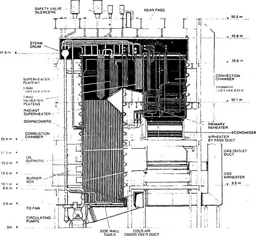
Fig. 2.23 500 MW coat-fired boiler designed for downshot firing and low volatile fuel
84

Station layout
KEY |
|
|
|
|
|
1 |
STEAM DRUM |
15 PRIMARY REHEATER |
28 VENTURI |
||
2 |
DOWNCOMER A |
15 SECONDARY REHEATER |
» FORCED DRAUGHT FAN |
||
3 |
DOWNCOMERS |
17 |
STEAM PARTITION WALL |
30 |
PRIMARY AIR FAN SUCTION DUCT |
4 |
DOWNCOMER C |
18 |
REAR ENCLOSURE DIVISION WALL |
31 |
PRIMARY AIR FAN |
9 DOWNCOMER 0 |
10 SAFETY VALVE SILENCERS |
32 |
PRIMARY AIR FAN DISCHARGE DUCT |
||
8 FURNACE SIDEWALL |
20 |
COAL BUNKER |
33 |
MILL AIRHEATER |
|
7 |
WATER SEAL |
21 |
BUNKER OUTLET VALVE |
34 |
HOT AIR BUS MAIN |
8 |
ASH HOPPER |
22 |
COAL FEEDER |
35 |
MAIN AIRHEATER |
9 |
DESUPERHEATER |
23 |
PULVERISING MILL |
38 |
GAS OUTLET TO PRECIPITATORS |
10 |
ECONOMISER |
24 |
FOUR - WAY DISTRIBUTOR |
37 |
COAL CONVEYORS |
11 |
PRIMARY SUPERHEATER |
25 |
BURNER |
38 |
DEAERATOR |
12 |
STEAM DIVISION WALL |
28 FORCED DRAUGHT FAN AIR INLET |
39 |
DEAERATOR STORAGE TANK |
|
13 |
PLATEN SUPERHEATER |
27 COMBUSTORS |
40 RESERVE FEED WATER TANKS |
||
14 |
SECONDARY SUPERHEATER |
|
|
|
|
Fig. 2.24 500 MW coal-fired boiler designed for frontwall firing and UK bituminous fuel
85

Station design and layout |
Chapter 2 |
Current station layout practice within the CEGB does not favour mirror imaging plant layout but is based on replication of complete boiler/turbine packages.
6.3.3Turbine island concept
It is conventional practice for turbine-generators to.be supported by foundation blocks which are elevated above the basement or ground floor level of the power station. The height at which the turbine-generator is located is termed the operating floor and the designer has to decide whether to install a complete floor throughout the turbine house at this level or just to elevate the turbine-generator and its immediate walk ways and local laydown areas for small turbine com ponents. The latter concept is shown in Fig 2.26.
Elevation to operating floor level of the turbine
generator alone is termed an island |
layout |
and has |
been adopted by the CEGB as its |
preferred |
option. |
This preference is based on the need to provide clear and unhindered access to main plant items. The layout allows direct crane access to all parts of the turbine hall, good maintenance access and efficient lighting and
ventilation to all areas. Defined laydown areas for heavy plant are provided at basement level as are clearways for personnel and equipment movement.
A continuous operating floor level throughout the turbine hall requires that the supporting structure be designed to accommodate plant loads imposed when the unit is dismantled for maintenance. Additionally, separate provisions for plant maintenance, ventilation and lighting arc required for the basement area or any intermediate floor levels.
The benefits claimed for the continuous operating floor are the opportunities for equipment location in intermediate floor levels, better facilities for turbine maintenance, ample laydown space local to the turbine and the generally pleasing and uncluttered appearance of the turbine hall.
Overall, the CEGB considers that the island concept provides the most economic and practical plant layout, and gives the best access and facilities for plant maintenance.
, The appearance of the turbine hall is a question of preference to be exercised by an individual utility, but the CEGB approach is that the station should be seen
86

' v U.5U eotour photograph between pp 66 and pp 67)
layout Station