

- •MODERN
- •POWER STATION PRACTICE
- •PERGAMON PRESS
- •Contents
- •Foreword
- •G. A. W. Blackman, CBE, FEng
- •Preface
- •Chapters 1 and 2
- •Chapter 3
- •Contents of All Volumes
- •CHAPTER 1
- •Power station siting and site layout
- •1 Planning for new power stations
- •1.1 Introduction
- •1.2 Capacity considerations
- •1.3 Economic considerations
- •1.4 Future requirement predictions
- •1.5 System planning studies
- •1.6 Authority to build a new power station
- •2 Site selection and investigation
- •2.1 Basic site requirements
- •2.3 Detailed site investigation
- •2.4 Environmental considerations
- •2.5 Site selection
- •3 Site layout — thermal power stations
- •3.1 General
- •3.2 Foundations
- •3.3 Site and station levels
- •3.4 Main buildings and orientation
- •3.5 Ancillary buildings
- •3.6 Main access and on-site roads
- •3.7 Station operation considerations
- •3.8 Cooling water system
- •3.9 Fuel supplies and storage
- •3.10 Ash and dust disposal
- •3.11 Flue gas desulphurisation plant materials
- •3.12 Transmission requirements
- •3.13 Construction requirements
- •3.14 Amenity considerations
- •3.15 Typical site layouts
- •4 Pumped storage
- •4.1 Introduction.
- •4.2 Suitable topology
- •4.3 Ground conditions
- •4.4 Site capacity
- •4.5 System and transmission requirements
- •4.7 Heavy load access
- •4.9 Environmental impact
- •5 Gas turbines
- •5.1 Introduction
- •5.2 The role of gas turbines
- •4.7 Heavy load access
- •Station design and layout
- •1 Introduction
- •2.1 Fossil-fired stations
- •2.2 Nuclear stations
- •2.3 Hydro-electric and pumped storage stations
- •2.4 Gas turbine stations
- •3 Future development options
- •3.1 Fossil-fired plant
- •3.2 Nuclear stations
- •3.3 Combined cycle gas turbines
- •3.4 Wind power
- •3.5 Tidal power
- •3.6 Geothermal energy
- •3.7 Combined heat and power
- •4 Station design concepts
- •4.1 Basic considerations
- •4.2 Design objectives
- •5 Plant operation
- •6 Station layout
- •6.1 General
- •6.2 Main plant orientation
- •6.3 Layout conventions
- •.7 Turbine-generator systems
- •7.1 Feedheating plant
- •7.2 Condenser and auxiliary plant
- •7.3 Erection and maintenance
- •8 Boiler systems
- •8.1 Pulverised fuel system
- •8.2 Draught system
- •8.3 Oil firing system
- •8.4 Boiler fittings
- •8.5 Dust extraction plant
- •8.6 Flue gas desulphurisation plant
- •9 Main steam pipework
- •10 Low pressure pipework and valves
- •11 Water storage tanks
- •12 Cranes
- •13 Fire protection
- •13.1 Introduction
- •13.2 Prevention of fires
- •13.3 Limiting the consequences of a fire
- •13.4 Reducing the severity of fires
- •14 Electrical plant layout
- •14.1 Introduction
- •14.2 Auxiliary switchgear
- •14.3 Turbine-generator auxiliaries
- •14.4 Main connections
- •14.5 Transformers
- •14.6 Cables
- •14.7 Batteries and charging equipment
- •14.8 Control rooms
- •15 Heating, ventilation and air conditioning
- •15.1 Introduction
- •15.2 Ventilation of nuclear stations
- •15.3 Smoke and fire control
- •15.4 General layout of HVAC plant
- •16 Air services
- •17 Water treatment plant
- •18 Cooling water plant
- •18.1 General design considerations
- •18.2 Cooling water pumphouse
- •18.3 Main cooling water pumps
- •18.4 Screening plant
- •18.5 Pump discharge valves
- •18.6 Section valves
- •18.7 Discharge pipework
- •18.8 Auxiliary systems
- •19 Chlorination plant
- •20 Coal handling plant
- •20.2 Water-borne reception and discharging
- •20.3 Road-borne reception and discharging
- •20.4 Coal storage
- •20.5 Conveyance from unloading point to station bunkers or coal store
- •20.6 Plant control
- •21 Ash and dust handling plant
- •21.1 Ash handling plant
- •21.2 Dust handling plant
- •21.3 Ash and dust disposal
- •22 Auxiliary boilers
- •23 Gas generation and storage
- •23.1 Hydrogen
- •23.2 Carbon dioxide
- •23.3 Nitrogen
- •23.4 Miscellaneous gases
- •24 Pumped storage plant
- •24.1 Hydraulic machines
- •24.2 Generator-motors
- •24.3 Main inlet valves
- •24.4 Draft tube valves
- •24.5 Gates
- •24.6 High integrity pipework
- •25 Gas turbine plant
- •25.1 Introduction
- •25.2 Operational requirements
- •25.3 Aero-engine-derivative gas turbines
- •25.4 Industrial gas turbines
- •25.5 Gas turbine power station layout
- •26 References
- •CHAPTER 3
- •Civil engineering and building works
- •Introduction
- •2 Geotechnical investigations
- •2.1 General and desk studies
- •2.2 Geophysical investigations
- •2.3 Trial excavations and boreholes
- •2.3 Trial excavations and boreholes
- •2.4 In-situ tests
- •2.5 Groundwater investigations
- •2.6 Ground description and classification
- •2.7 Laboratory tests
- •2.8 Factual reports
- •2.9 Interpretation of site investigations
- •3 Seismic hazard assessment
- •3.1 Geology
- •3.2 Earthquakes
- •3.3 Crustal dynamics
- •3.4 Ground motion hazard
- •3.5 Ground rupture hazard
- •4 Types of foundations
- •4.1 Isolated column foundations
- •4.2 Strip foundations
- •4.5 Piled foundations
- •4.5 Piled foundations
- •4.6 Caisson foundations
- •4.7 Anti-seismic foundations
- •5 Foundations design and construction
- •5.1 Concrete
- •5.2 Bearing pressures and settlement
- •5.3 Test piling
- •6 Foundations for main and secondary structures
- •6.1 Boiler house foundations
- •6.2 Turbine hall foundations
- •6.3 Turbine-generator blocks
- •6.4 Basement of ground floor
- •6.5 Track hoppers
- •6.6 Chimney foundations
- •6.7 Cooling tower foundations
- •6.8 Reactor foundations
- •7 General site works
- •7.1 Flood embankments
- •7.2 Roads
- •7.3 Drainage
- •7.4 Railways
- •7.5 Coal storage
- •7.3 Oil tank compounds
- •7.7 Ash disposal areas
- •8 Methods of construction
- •8.1 Site clearance, access roads and construction offices
- •8.2 Underground construction
- •8.3 Groundwater lowering
- •8.4 Excavating machinery
- •8.6 Formwork and reinforcement
- •8.7 Mixing and placing of concrete
- •9 Direct cooled circulating water systems
- •9.1 Civil engineering structures in direct cooling systems
- •9.2 Culverts
- •3.3 Pumphouse and screen chamber intake
- •9.4 Cooling water tunnels
- •9.5 Submersible cooling water structures
- •9.6' Maintenance considerations
- •10 Harbours and jetties
- •10.1 General
- •10.2 Types of harbours and jetties
- •10.3 Construction of harbours and jetties
- •11 Loadings
- •11.1 Definitions
- •11.2 Imposed loads due <o plant
- •11.3 Distributed imposed loads
- •II. 6 Reduced loadings in main beams and columns
- •11.4 Cranes
- •11.5 Wind and snow loads
- •12 Steel frames
- •12.1 Steelwork
- •13 Reinforced concrete
- •13.1 General
- •13.2 Formwork
- •13.3 Reinforcement
- •1^.4 Design of reinforced concrete
- •12.2 Design of members
- •12.3 Connections
- •12.4 Protection of steelwork
- •13.5 Movement joints
- •13.6 Curing
- •13.7 Precast concrete
- •14 Prestressed concrete
- •14.1 Prestressing
- •14.2 Prestressed piling
- •14.2 Prestressed piling
- •14.3 Prestressed concrete pressure vessels and containments
- •15 Brickwork and blockwork
- •15.1 General
- •15.2 Bricks
- •15.3 Mortar
- •15.4 Brickwork
- •15.5 Blocks
- •15.8 Openings
- •15.6 Blockwork
- •16 Lightweight walling systems
- •16.1 Sheeting
- •16.2 Insulation
- •16.3 Fixings
- •16.4 Durability
- •17 Roofing
- •17.1 Structural elements
- •17.2 Insulation and weatherproofing layers
- •17.3 Application to power stations
- •17.4 Durability
- •17.5 Rainwater disposal
- •18 Finishes
- •18.1 Floor finish considerations
- •18.2 Types of floor finish
- •18.3 Finishes to walls and ceilings
- •18.4 Wall tiling and other special finishes
- •18.5 Internal painting
- •18^6 External painting
- •19 Turbine hall and boiler house construction
- •19.1 General
- •19.2 Structural considerations
- •19.3 Erection of steelwork
- •19.4 ''Cladding
- •19.5 Ventilation
- •19.6 Floor and wall finishes
- •20 Reactor construction
- •20.1 Reactors
- •20.2 Reactor buildings
- •21.2 Control room building
- •21.3 Gas turbine house
- •21.4 CW pumphouse
- •21.6 Workshops and stores
- •21.7 Offices, welfare blocks, laboratories and similar buildings
- •22 Chimneys, cooling towers and precipitators
- •22.1 Chimneys
- •22.2 Cooling towers
- •22.3 Precipitators
- •23 Architecture and landscape
- •23.1 General power station architecture
- •23.2 Landscape considerations
- •23.3 Preparatory works
- •23.4 Landscape layout
- •24 Regulations
- •24.1 Government instruments
- •24.2 Factories Act
- •24.4 Building regulations
- •24.5 Nuclear station licensing
- •25 Civil engineering contracts
- •25.2 Forms of contract
- •25.3 Contract strategy
- •25.4 Contract placing
- •25.5 Contract administration
- •25.6 Budgetary approval and control
- •26 References
- •Appendix A
- •SUBJECT INDEX
Civil engineering and building works |
Chapter 3 |
of safety related structures are conveniently similar. The concrete sizes, reinforcement proportions anil distribution thus derived are likely to be shown by analysis to be suitably resistant to collapse when threatened by the occurrence of the SSE.
The .serious student of the design of reinforced concrete power plant superstructures would be well advised to consult references [23] and [24], The first of these comprehensively covers the broader aspects of the structural design and analysis of nuclear power stations including impulsive and impactive (missile) loading; the second covers in depth reinforced concrete analysis, behaviour and detailing (particularly with respect to aseismic design and American research and practice).
Commercial (non-safety-related) structures (such as administration buildings and stores) at nuclear power plants could also be designed to ACI 318M, but it is probably more convenient to use BS8110 as for conven tionally-planted thermal stations. Here again reference [24] contains very useful information on the behaviour and detailing of reinforced concrete elements; an understanding of this is required to achieve safe, serviceable and durable structures.
rot-proof compressible boarding (as used in concrete retaining walls, slabs anil similar structure), to ilic complicated roller, rocker or sliding joints provided at the end of bridge or similar beams.
Expansion gaps in walls and slabs can be made water tight if necessary by incorporating a suitable water bar and sealant. Expansion joints in buildings must be carefully located and made weatherproof by providing cappings at joints in roofs and in the use of copper water bars or similar methods of sealing vertical walls.
.< Care must be taken with the treatment of internal finishes at the positions where expansion joints are located, plates being used on the floors and cover strips or other features being used on walls or ceilings to permit sliding and prevent cracking of plaster or other finishings.
It should be noted that construction joints are not considered to be movement joints. They are introduced to divide the structure into conveniently sized sections for casting. The reinforcement is continuous across the joint and the face of the joint is prepared to encourage continuity of the concrete. In practice, however, shrinkage frequently occurs at construction joints con verting them cll'cclivcly into contraction joints.
13.5 Movement joints
Movement joints are joints which can accommodate relative movement between the adjoining parts ot a member or structure. The principal movements which may have to be accommodated are as follows:
(a) Expansions and contractions due to thermal movement and drying shrinkage of the concrete. An indication of the possible magnitude of these movements is given in BS8110 Part 2 [3].
(b)Rotation and/or translocation at a connection.
(c)Long term increase in deflection due to creep of the concrete.
If the movements noted under item (a) are restrained, stresses will build up which can crack the concrete. Where cracking cannot be reduced to acceptable levels by other means, movement joints are introduced.
The following types of movement joint are com monly used in power station construction:
Contraction joint This type of joint is generally used in slabs and walls to permit contraction of the concrete. Initially there is no gap between the concrete on either side of the joint and the reinforcement may be con tinuous or discontinuous across the joint. Where it is necessary to achieve a watertight joint, a suitable rubber or neoprene water bar and joint sealant is incorporated.
Expansion joint Expansion joints are designed to accommodate both expansion and contraction. They can vary in complexity from a simple gap filled with
13.6 Curing
Curing is the process ot keeping the concrete saturated whilst maintaining the temperature within suitable limits during the early stages ol hardening.
Concrete hardens as a result of hydration ol the cement. Hydration can only take place when the pores in the concrete are adequately wet and the tinal strength partially depends on the extent to which hydration has taken place. The temperature of the concrete determines the rate at which hydration takes place and hence the rate of strength development.
Keeping the concrete saturated during the early stages of hardening is achieved by preventing loss of moisture by evaporation from the surface. The most Common methods of preventing loss of moisture include retaining formwork in position, spraying or flooding the surface with water, covering the surface with a damp absorbent material, covering the surface with a waterproof membrane such as polythene and spraying the surface with a sealing compound. Curing should commence immediately the concrete has set to prevent premature drying out of the surface.
The perio.d of curing required depends on the type of cement, the ambient conditions and the temperature of the concrete. BS8110 Part 1 lays down the minimum curing periods taking these factors into account. For example, the minimum curing period for concrete made with ordinary Portland cement, under average ambient conditions and at an average surface tempera ture of 5-10°C, is four days.
252
|
|
|
|
|
|
|
|
|
|
|
|
|
|
|
|
|
|
|
|
|
|
|
|
Reinforced concrete |
|||||
The next generation of UK nuclear plant |
starting |
W |
= |
operating wind load |
|
|
|
|
|
||||||||||||||||||||
with |
Sizewell |
B will |
have pressurised |
water |
reactors |
Ro = |
|
pipe and equipment reactions |
|
|
|
||||||||||||||||||
(PWRs). Analysis of the seismic response of the main |
|
|
|
|
|||||||||||||||||||||||||
|
|
|
|
|
|
|
|
|
|
|
|
|
|
|
|
||||||||||||||
structures for Sizewell is discussed in ‘Seismic Design |
To |
= |
thermal |
effects |
during |
normal operation |
or |
||||||||||||||||||||||
Approach for the Sizewell B Nuclear Power Plant [21], |
|
|
|
shutdown |
|
|
|
|
|
|
|
|
|||||||||||||||||
which includes the background to soil-structure interac |
Ess |
= |
load |
effects of safe shutdown |
earthquake |
||||||||||||||||||||||||
tion (SSI)' analysis. However, it should be noted that in |
|||||||||||||||||||||||||||||
the early stages of analysis the ground motion is applied |
|
|
|
|
(SSE) |
|
|
|
|
|
|
|
|
||||||||||||||||
Wt |
= |
loads |
|
generated |
by |
extreme |
wind |
or related |
|||||||||||||||||||||
directly to the foundations in order to estimate |
the |
|
|||||||||||||||||||||||||||
gross loads for calculation of stresses. This procedure |
|
|
|
|
internal forces and moments |
|
|
|
|||||||||||||||||||||
will |
be shown |
to be |
conservative by comparison |
with |
U |
= |
required |
strength |
to |
resist |
factored |
|
loads |
or |
|||||||||||||||
the global SSI analysis at a later date. Civil design and |
|
||||||||||||||||||||||||||||
|
|
|
|
related internal forces and moments |
|
|
|
||||||||||||||||||||||
analysis work may thus proceed independently of the |
|
|
|
|
|
|
|
||||||||||||||||||||||
Then typical design load combinations are: |
|
|
|
||||||||||||||||||||||||||
SSI analysis so that the iterations which would other |
|
|
|
||||||||||||||||||||||||||
wise be necessary |
between these |
two parts of |
the |
U |
= |
1.4D |
+ 1.4F + 1.7L + 1.7H + 1.7W + |
|
1.7Ro |
||||||||||||||||||||
seismic design process are avoided. Whilst the section |
|
||||||||||||||||||||||||||||
U |
= |
D + |
|
F + L + H + To + Ro + Em |
|
|
|
||||||||||||||||||||||
sizes are determined by adopting a fixed base type of |
|
|
|
|
|||||||||||||||||||||||||
analysis it |
still remains |
possible |
to |
benefit |
from a |
U = D + F + L + H + T„ + Ro + W, |
|
|
|
||||||||||||||||||||
subsequent SSI analysis in the design of reinforcement. |
|
|
|
||||||||||||||||||||||||||
Although |
the |
section |
strengths |
determined |
in |
accord |
|||||||||||||||||||||||
The demonstration |
that |
structures |
can withstand the |
||||||||||||||||||||||||||
ance |
with |
ACI |
349 |
are |
similar |
to |
the ULS |
strengths |
|||||||||||||||||||||
loading which |
is imposed |
on them |
during the SSE is |
||||||||||||||||||||||||||
of |
BS8110, |
appropriate |
adjustment |
must be |
made |
to |
|||||||||||||||||||||||
carried out using analysis procedures in line with inter |
|||||||||||||||||||||||||||||
account |
for |
the |
different |
materials and strength testing |
|||||||||||||||||||||||||
nationally accepted standards and practices. As there is |
|||||||||||||||||||||||||||||
methods in the UK. Appendix C of ACI 349 deals with |
|||||||||||||||||||||||||||||
a CEGB commitment that the plant will be manifestly |
|||||||||||||||||||||||||||||
special provisions for impulsive and impactive effects. |
|
||||||||||||||||||||||||||||
licensable in the USA (the country of origin), Sizewell |
|
||||||||||||||||||||||||||||
Plant |
in |
the |
second category |
comprises items which |
|||||||||||||||||||||||||
and |
probably |
future |
PWR plant |
concrete structures |
|||||||||||||||||||||||||
are |
not |
themselves required |
to |
function after |
the SSE |
||||||||||||||||||||||||
(excluding |
reactor |
containment) in the UK |
will be |
||||||||||||||||||||||||||
but whose |
failure could imperil other plant of the first |
||||||||||||||||||||||||||||
analysed and designed in accordance with AC1 349-80 |
|||||||||||||||||||||||||||||
category. The |
design |
bases |
have to |
ensure |
that where |
||||||||||||||||||||||||
[22]. |
|
|
|
|
|
|
|
|
|
|
|
||||||||||||||||||
|
|
|
|
|
|
|
|
|
|
|
relevant: |
|
|
|
|
|
|
|
|
|
|
|
|
||||||
There are two categories of plant at a PWR station |
|
|
|
|
|
|
|
|
|
|
|
|
|||||||||||||||||
|
|
|
|
|
|
|
|
|
|
|
|
|
|
|
|
||||||||||||||
for which a capability to withstand the SSE must be |
• The failure of whole or part of a second-category, |
||||||||||||||||||||||||||||
demonstrated. Plant in the first category is required to |
structure docs not jeopardise the integrity of a first- |
||||||||||||||||||||||||||||
function after the SSE so that safe shutdown can be |
category structure, system or component. |
|
|
|
|||||||||||||||||||||||||
achieved. The |
design |
bases are |
defined to ensure |
that |
• |
Radiological |
protection is maintained as appropriate |
||||||||||||||||||||||
where relevant: |
|
|
|
|
|
|
|
|
|
|
|||||||||||||||||||
|
|
|
|
|
|
|
|
|
|
for structural elements or the structures as a whole. |
|
||||||||||||||||||
• The safety |
related |
structures |
or |
structural |
members |
|
|||||||||||||||||||||||
It is often impractical to provide sufficient separation so |
|||||||||||||||||||||||||||||
do not |
collapse |
or severely |
distort |
such that |
con |
||||||||||||||||||||||||
that second-category structures would not impinge on |
|||||||||||||||||||||||||||||
tinued |
operation |
of |
safety |
related |
plant |
is |
pre |
||||||||||||||||||||||
first-category structures if they collapsed. Either they |
|||||||||||||||||||||||||||||
judiced. |
|
|
|
|
|
|
|
|
|
|
|
||||||||||||||||||
|
|
|
|
|
|
|
|
|
|
|
must be designed as first-category structures (which is |
||||||||||||||||||
• |
Structural |
integrity |
is |
maintained |
to ensure |
that |
|||||||||||||||||||||||
not always economic) or their integrity must be demon |
|||||||||||||||||||||||||||||
there are no releases of air or liquid-borne radio |
strated by inelastic dynamic analysis to show that under |
||||||||||||||||||||||||||||
activity |
in excess |
of |
the targets |
defined, |
or losses |
the SSE the deformations are well below those levels |
|||||||||||||||||||||||
of radiological protection. |
|
|
|
|
|
that lead to collapse. This second (inelastic) design |
|||||||||||||||||||||||
This is most conveniently achieved by working to the |
option is the most demanding of expertise, since it |
||||||||||||||||||||||||||||
methods and design criteria of ACI 349 which will |
requires rigorous assessment of the damping and duc |
||||||||||||||||||||||||||||
ensure that when subjected to various combinations of tilities appropriate to the structural behaviour and
gravity, wind, thermal, seismic and accidental loads |
advanced numerical analysis techniques. The reinforce |
the structures will behave generally in a linear-elastic |
ment distribution and detailing must be correct to |
manner. Elastic behaviour is considered as limited by |
achieve the ductility and hence energy absorption im |
the yield stress of the effective load-carrying structural plicit in the inelastic analysis. In order to arrive at the
materials or ultimate capacity of an element. |
proportions and reinforcement of a second-category |
|||
|
Thus using the nomenclature of ACI 349, if: |
structure which can then be analysed for resistance to |
||
D |
= |
dead loads |
collapse, it is probably most convenient to work within |
|
the code requirements of ACI 318M-83 [23], from |
||||
|
|
|
||
F |
= |
lateral andvertical pressure of liquids |
which ACI 349-80 was developed. The format is |
|
L |
= |
live loads |
common to both codes (though appendices are differ |
|
ent as they relate to separate areas) and therefore the |
||||
|
|
|
||
H |
= |
lateral earthpressure |
methods for the design and analysis of both categories |
|
251
Civil engineering and building works |
Chapter 3 |
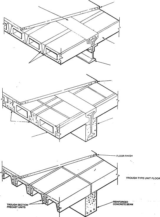
FINE CONCRETE
FILLING
REINFORCEMENT
PRECAST
PRESTRESSED
BEAMS
LIGHT CONCRETE
IN-FILL BLOCKS
FLOOR FINISH
HOLLOW BEAM FLOOR
BOX SECTION
PRECAST UNITS
WITH ENDS CUT
AWAY TO FIT
TOP FLANGE OF
BEAM
STEEL BEAM WITH
SHELF ANGLES
FLOOR FINISH
PRESTRESSED BEAM AND IN-FILL UNIT FLOOR
STEEL BEAM WITH
BOTTOM FLANGE
ENCASED IN
CONCRETE AS
ALTERNATIVE
METHODOF
SUPPORT TO FLOOR
UNITS
Fig. 3.43 Precast concrete floors
254